
Abstract
Background:
Despite the rare entity of sternoclavicular joint (SCJ) instability, a variety of different reconstruction techniques for SCJ dislocations have been described. A technique with oblique drilling has been proposed to reduce intraoperative risks.
Purpose:
To biomechanically investigate different cerclage reconstruction techniques and the benefit of additional reinforcement using suture tape.
Study Design:
Controlled laboratory study.
Methods:
Reconstructed artificial bone specimens were mounted on a mechanical testing machine. They were subjected to anterior and posterior translation, analyzing ultimate strength, displacement, stiffness, and elongation. For stage 1, different angulations of the drill tunnels through the sternum and clavicle were compared. Straight drill tunnels from anterior to posterior were compared with 45° oblique drill tunnels. For stage 2, three different materials for cerclage reconstruction were compared: (1) suture tape alone (FT group), (2) tendon graft alone (tendon group), and (3) tendon graft with suture tape augmentation (tendon+FT group).
Results:
For the FT group, in the anterior and posterior directions, straight drill holes resulted in a significantly higher load to failure (936.9 ± 122.5 N) compared with oblique ones (434.5 ± 20.2 N) (P < .0001). During cyclic testing, all specimens with straight drill holes survived the 5- to 550-N step, while all specimens with oblique ones failed during the 5- to 450-N step. Analyzing the graft material choice, the mean load to failure was 556.6 ± 174.3 N for the tendon group, 936.9 ± 122.5 N for the FT group, and 767.0 ± 110.7 N for the tendon+FT group (P = .089). The stiffness of the tendon+FT group was significantly lower than that of the FT group and significantly higher than that of the tendon group.
Conclusion:
Oblique tunnel placement during SCJ reconstruction, while reducing the intraoperative risk, results in decreased primary stability of the construct. Tendon graft reconstruction with suture tape augmentation leads to enhanced stability and optimizes biomechanical properties of the construct.
Clinical Relevance:
The surgical technique with straight drill holes has superior initial biomechanical properties and may likewise produce superior clinical outcomes in the treatment of SCJ instability. Suture tape augmentation can provide additional stability to reconstruction procedures.
Although injuries to the sternoclavicular joint (SCJ) occur in only 3% of all shoulder injuries and only 1% of all dislocations in the body affect this joint, these injuries can cause ongoing impairment of shoulder function or even be life threatening because of their proximity to vital structures. 10,20,22 Therefore, a surgical intervention might be indicated in painful chronic instability cases or unreduced acute posterior dislocations. Despite the low case numbers of SCJ instability, a great variety of reconstruction techniques have been described in the literature. 5,6,9,16,18,23,27 Since Spencer and Kuhn 27 described the excellent biomechanical properties of a “figure-of-8” graft augmentation technique in 2004, several studies have demonstrated good clinical outcomes when performing this technique. 2,4,13,23,30,34 For this technique, drill holes are placed in the medial clavicle and the sternum in the anterior-posterior direction, putting at risk several important retrosternal structures. Before drilling, it is mandatory to place a protective malleable retractor behind the medial clavicle and the sternum, which requires extensive posterior dissection in a dangerous region. 19,20,23,25,34 In 2016, a modified figure-of-8 technique for stabilization of the SCJ was first described. 18 The authors recommended using oblique drill holes that exit in the posterior third of the joint face instead of drilling through the posterior cortex. This technique obviates the need for extensive posterior dissection, thus minimizing the risks of the procedure.
Based on this background, the purpose of the present study was to biomechanically compare the originally used technique to the modified technique using oblique drill holes. Additionally, the influence of the material used for cerclage on biomechanical properties was investigated. The hypothesis of the study was that oblique drilling would not significantly decrease stability of the construct. Furthermore, it was hypothesized that additional suture tape cerclage, also described as internal bracing, which reinforces and protects the ligaments or grafts during the healing process, 7,12 would significantly improve primary construct stability.
Methods
This study was split into 2 stages. Stage 1 consisted of 2 groups with 5 specimens per group. Stage 2 consisted of 3 groups with 5 to 6 specimens per group. For reconstruction with a tendon graft alone, 6 specimens were used to reduce potential bias from varying tendon properties.
Specimen Preparation
The tests were performed on artificial bone made of solid rigid polyurethane foam (fourth-generation Sawbones; Pacific Research Laboratories Inc). Previous studies have reported comparable failure modes, stiffness, and strength between composite bones and cadaveric bones, without the anatomic variability present in cadaveric models. 8,11,14 As is the case for any study performed with composite bone or an in vitro model, the in vivo biological aspects for healing were not present, and the results were predictive of repair at time zero.
The dimensions of the clavicle of the developed model were set according to Van Tongel et al, 33 who measured in the anterior-posterior and superior-inferior directions. The mean overall dimension of the clavicle (both anterior-posterior and superior-inferior) was 23 ± 3 mm. The thickness of the sternum was obtained by evaluating computed tomography scans provided by the Institute of Radiology at Klinikum Rechts der Isar. The mean thickness was 14 ± 2.5 mm.
Drill hole parameters for cerclage reconstruction were based on recently published techniques by Martetschläger and Imhoff 19 and Petri et al. 23 These parameters were the same for the clavicle and sternum. The distance of the drill holes to the articulating surface was 10 mm, and the distance of the 2 drill holes to each other was 15 mm. The drill diameter was 4 mm. A 2 mm–thick plate of polyoxymethylene thermoplastic material was affixed to the sternum as an equivalent for the intra-articular disc.
In stage 1, the 2 drill hole directions were compared with each other. FiberTape (Arthrex) was used as cerclage material to ensure stability of the drill hole directions. The standard technique with straight drill holes leading from anterior to posterior was compared with a modified cerclage technique with oblique drill holes leading from anterior at a 45° angle toward the joint surface (Figure 1).

Cerclage reconstruction techniques. (A) Straight drill holes from anterior to posterior and (B) oblique drill holes at a 45° angle from anterior toward the joint surface.
The tests for stage 2 were then performed with drilling from stage 1 that granted a greater resistance to failure. In stage 2, different reconstruction materials were compared with each other. Reconstruction with suture tape alone (FT group) was compared with reconstruction with a tendon graft alone (tendon group) as well as tendon graft reconstruction with suture tape augmentation (tendon+FT group) (Figure 2). Consistent 4.0 mm–diameter human tendons (peroneus longus, tibialis anterior, tibialis posterior) were used to reduce variability. With all materials for stages 1 and 2, a figure-of-8 reconstruction technique was performed.
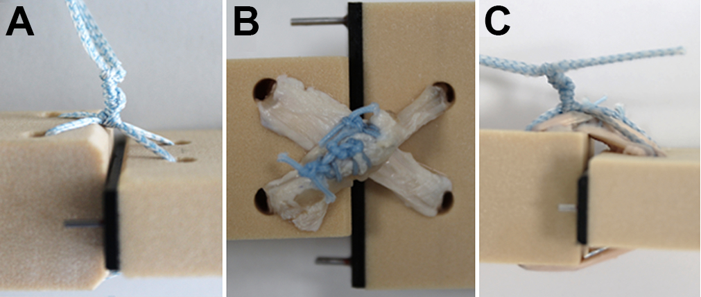
Reconstruction material configurations: (A) FiberTape only, (B) tendon graft only, and (C) FiberTape augmentation.
The tendon was stitched using high-strength suture material (FiberWire; Arthrex) and FiberTape knotted on the anterior side. The specimens were then placed in a custom-made fixation device with the anterior side facing up. The sternum was clamped tight to avoid movement. The clavicle was fixed to the actuator of a tensile testing machine (ElectroPuls E10000; Instron) using 4 fixation pins. Clavicle fixation ensured that loads were applied in the middle of the clavicle to avoid rotation. A 2-kN load cell was used to apply loads in the anterior-posterior direction on the clavicle (Figure 3).

Testing setup. The sternum is clamped to a block to avoid any movement. The clavicle is fixed to the moving device of the testing machine. It is held in position by 4 fixation pins. The setup allows the clavicle to only move in the vertical plane, which simulates movement in the anterior-posterior direction of the joint.
Testing Protocol
For stages 1 and 2, consistent cyclic testing was developed. The specimens were preloaded to 5 N for 10 seconds. 27 Then, force-controlled cyclic testing was performed. Cyclic testing was split into several steps. The first step cycled the specimens from 5 to 50 N and the second one from 5 to 100 N. The third step ranged from 5 to 150 N. This procedure was continued until the last step cycled the specimens between 5 and 550 N; 550 N was defined as the clinical failure force according to the results of Spencer et al. 28 In each stage, the specimens cycled 200 times at a rate of 1 Hz. At the end of the cyclic phase, the specimens had undergone 2200 cycles. The cyclic tests simulate realistic behavior of the recovery phase after surgery, as the construct is loaded step by step to the ultimate failure load, allowing reconstruction to hold first before it is pulled to failure. If the specimens did not fail during the cyclic phase, position-controlled pull to failure was performed at a rate of 0.25 mm/s, with failure being defined as displacement identical to the diameter of the medial end of the clavicle in the anterior-posterior direction. 27 In each group, 5 specimens were tested in the anterior direction toward the knot and stitches, and another 5 specimens were tested in the opposite direction to examine the influence of the knot and stitches.
Statistical Analysis
Statistical analysis was performed with the use of PASW Statistics (v 18; IBM). The study compared data for each group using 1-way analysis of variance. For analyses of variance that demonstrated a statistically significant difference, a post hoc Tukey honest significant difference test was conducted to assess the mean values that were statistically significant between the groups. A statistically significant difference was determined to be present for P < .05. Assuming a standard deviation of ±5%, a sample size calculation was performed using PS version 3.0 (Vanderbilt University) (α = .05). The number of samples required with a power of 0.8 was 5 per group.
Results
Stage 1: Influence of Drill Hole Direction
Survival During Cyclic Testing
All specimens with straight drill holes survived the 5- to 550-N cyclic testing step, whereas all specimens with oblique drill holes failed during cyclic testing up to 450 N. Although 80% of the specimens with oblique drill holes that were tested in the posterior direction survived the 5- to 350-N step, only 40% survived the 5- to 400-N step. The rest of the specimens failed during the 5- to 450-N step. The behavior of the specimens with oblique drill holes that were tested in the anterior direction was slightly different. Most specimens (80%) failed during the 5- to 400-N step. The remaining 20% failed during the 5- to 450-N step (Figure 4).

Survival curves of stage 1 testing.
Ultimate Failure Load
The specimens with oblique drill holes failed at a mean load of 437.6 ± 37.5 N when forced in the posterior direction and 434.5 ± 18.0 N when applied in the anterior direction. The mean failure loads of the specimens with oblique drill holes were not significantly different (P = .442).
The specimens with straight drill holes that were tested in the posterior direction had a mean failure load of 992.0 ± 50.2 N. The specimens with straight drill holes that were tested in the anterior direction had a mean failure load of 936.9 ± 122.5 N. There was no significant difference between the posterior and anterior directions in specimens with straight drill holes (P = .215). When comparing the different directions, specimens with straight drill holes showed significantly higher anterior and posterior ultimate failure loads (P = .00002 and P < .00001, respectively).
Stiffness
All specimens showed a decline in stiffness during the second cyclic step (5-100 N). The mean maximal stiffness during cyclic testing of the specimens with straight drill holes was 166.0 ± 1.9 N/mm when tested posteriorly and 167.7 ± 7.1 N/mm when tested anteriorly (P = .318).
The specimens with oblique drill holes all failed before reaching the end of cyclic testing. Therefore, the maximal stiffness of the specimens with oblique drill holes was calculated in the cyclic step before more than half of the specimens failed. The mean maximal stiffness was 162.3 ± 5.0 N/mm when tested posteriorly and 173.9 ± 10.6 N/mm when tested anteriorly (P = .0596).
Displacement
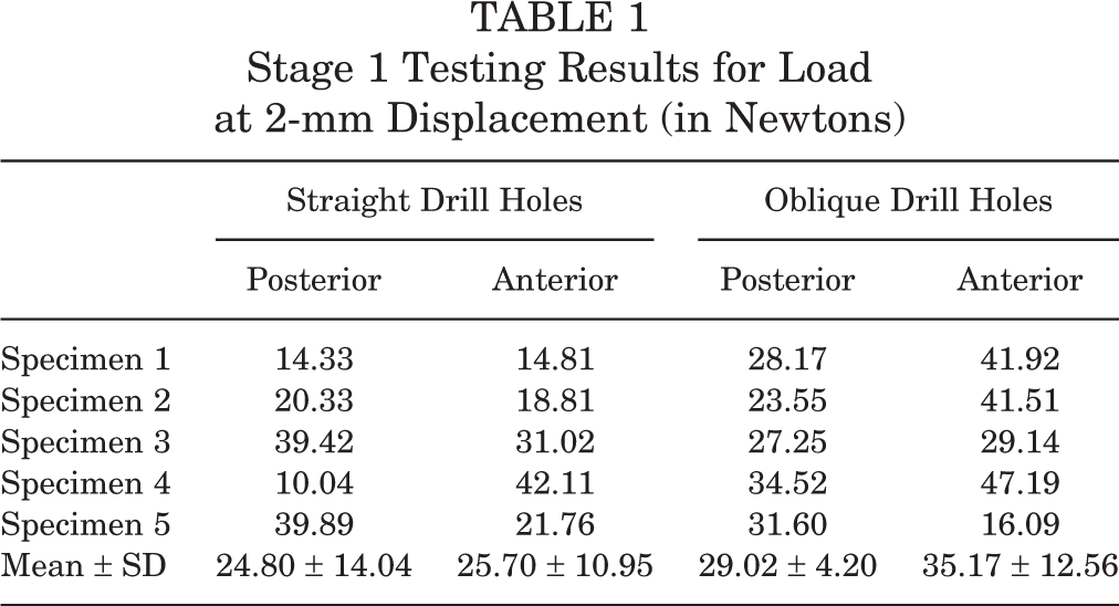
The load at a displacement of 2 mm was measured. The specimens with straight drill holes reached a mean force of 24.80 ± 14.04 N when tested in the posterior direction and 25.70 ± 10.95 N when tested in the anterior direction. There was no significant difference between the posterior and anterior directions (P = .913). The specimens with oblique drill holes reached a mean force of 29.02 ± 4.20 N when tested posteriorly and 35.17 ± 12.56 N when tested anteriorly (P = .329). There was no significant difference between the straight and oblique drill holes (Table 1).
Stage 1 Testing Results for Load at 2-mm Displacement (in Newtons)
Failure Mechanism
Investigating the failure mechanisms, it could be observed that among the specimens, the mode of failure was consistent. All specimens with straight drill holes tested in the posterior direction failed by breakage of the Sawbones representing the clavicle. The specimens with straight drill holes tested anteriorly failed by breakage of the sternal Sawbones. The behavior of breakage for all specimens with oblique drill holes was similar, as the suture tape cut through the bone bridges, breaking through the Sawbones. The only difference was that the specimens that were tested in the posterior direction failed on the side of the clavicle, whereas the specimens that were tested anteriorly failed on the side of the sternum.
Stage 2: Influence of Reconstruction Material
Survival During Cyclic Testing
The specimens in the tendon group tested in the posterior direction did not reach the end of the cyclic phase; 83% reached the 5- to 200-N step, and at the end of this step, 67% were left. Only 50% of the specimens reached the 5- to 350-N step. At the end of the 5- to 400-N step, 33% of the specimens were left, all of which failed during the 5- to 450-N step. Of the tendon group that was tested anteriorly, 83% survived the 5- to 300-N step; 67% were left after the 5- to 350-N step. After the 5- to 500-N step, 50% were left, and 33% survived until the pull-to-failure phase. The tendon+FT group showed a more consistent failure behavior, as 50% of the specimens that were tested in the posterior direction and 80% that were tested in the anterior direction reached the pull-to-failure phase (Figure 5).

Survival curves of stage 2 testing. FT, FiberTape.
Ultimate Failure Load
The mean ultimate failure load for the anterior and posterior directions was 936.9 ± 122.5 and 992.0 ± 50.2 N for the FT group, 556.6 ± 174.3 and 354.9 ± 121.4 N for the tendon group, and 767.0 ± 110.7 and 672.5 ± 128.8 N for the tendon+FT group, respectively (Table 2). There was a significant difference between the tendon and the FT groups in the posterior direction (P < .00001) and between the tendon and tendon+FT groups in the posterior direction (P = .0012). Furthermore, there was a significant difference between the tendon and FT groups in the anterior direction (P = .0024) and the tendon and tendon+FT groups in the anterior direction (P = .0319). There was also a significant difference between the FT and tendon+FT groups in the posterior direction (P = .0005) and the FT and tendon+FT groups in the anterior direction (P = .03676).
Stage 2 Testing Results for Ultimate Failure Load (in Newtons) a

a FT, FiberTape.
Stiffness
The mean maximal stiffness of the FT group was 166.0 ± 1.9 N/mm when tested posteriorly and 167.7 ± 7.1 N/mm when tested anteriorly (P = .318). The mean maximal stiffness of the tendon group was 75.0 ± 13.3 N/mm when tested posteriorly and 102.6 ± 5.9 N/mm when tested anteriorly (P = .0084). The majority of the specimens failed before reaching the end of cyclic testing. Therefore, the maximal stiffness of the specimens with tendon reconstruction was calculated in the cyclic step before more than half of the specimens failed. The mean maximal stiffness of the tendon+FT group that was tested posteriorly was 126.8 ± 3.5 N/mm, and it was 128.6 ± 9.4 N/mm when tested anteriorly (P = .397).
Displacement
The force at 2-mm displacement was measured. The FT group that was tested in the posterior direction reached a mean force of 24.80 ± 14.04 N. The FT group that was tested in the anterior direction reached a mean force of 25.70 ± 10.95 N. There was no significant difference between the directions for the FT group (P = .913). The tendon group reached a mean force of 10.39 ± 3.68 N when tested posteriorly and 7.69 ± 4.48 N when tested anteriorly (P = .281). The tendon+FT group that was tested posteriorly reached a mean force of 37.82 ± 9.48 N and 22.52 ± 5.49 N when tested anteriorly (P = .011). There was a significant difference in the load at 2-mm displacement between the following: tendon+FT group in the anterior and posterior directions (P = .011), FT and tendon groups in the anterior direction (P = .004), tendon+FT and tendon groups in the anterior direction (P = .014), and tendon and tendon+FT groups in the posterior direction (P = .005) (Table 3).
Stage 2 Testing Results for Load at 2-mm Displacement (in Newtons) a

a FT, FiberTape.
Failure Mechanism
All specimens in the tendon group that were tested posteriorly failed by tendon elongation and ruptures on the posterior side of the construct. A variance could be observed in the tendon group that was tested anteriorly. Five of 6 specimens failed because of graft elongation. One specimen failed by breakage of the sternum. The failure mechanisms of the tendon+FT group correlated with the mechanisms of the FT group. The posteriorly tested specimens failed by breakage of the clavicle, whereas the specimens that were tested anteriorly failed by breakage of the sternum.
Discussion
In the present study, biomechanical stability of both figure-of-8 techniques was compared, and the influence of the cerclage materials used was investigated. The results demonstrated that figure-of-8 reconstruction with straight drill holes shows greater biomechanical strength in the anterior and posterior directions compared with the modified technique with oblique drill holes. While surgical procedures aim to achieve the highest possible strength of a repair construct, the true in vivo forces transmitted through the SCJ during daily activities remain widely unknown. Forces that are expected to act within the SCJ during load-bearing activities of daily living ranged between 112 and 228 N in a wheelchair study. 31 Therefore, all proposed techniques, including the less risky technique with oblique drill holes, can safely retain stability during the postoperative healing phase.
Although the clinical results of the described technique with oblique drill holes are promising, 18 the biomechanical drawbacks found in the current study need to be considered. Also, the potential development of SCJ osteoarthritis by damaging the joint cartilage should be mentioned as a possible drawback of the oblique drill hole technique. From a biomechanical perspective, the original technique as described by Spencer and Kuhn 27 results in a more stable construct. In their study from 2004, Spencer and Kuhn 27 showed that the original figure-of-8 semitendinosus graft reconstruction was biomechanically superior to intramedullary ligament reconstruction and subclavius tendon reconstruction.
However, for the figure-of-8 technique with straight anterior-to-posterior drill holes, extensive retrosternal dissection is mandatory, and any surgeon needs to balance the pros and cons of the techniques for himself/herself and the patient. Finally, further clinical follow-up is necessary for this technique and its modifications to determine the optimal treatment.
In terms of cerclage materials, several orthopaedic techniques of internal bracing have been introduced recently, which use suture tape material for temporary fixation until healing of the disrupted structures occurs. # Tytherleigh-Strong et al 29 recently reported on a cohort of first-time SCJ dislocations treated with capsular repair and additional “internal bracing” with a high-strength suture material. They were able to show that this technique without graft augmentation can prevent recurrent instability in acute anterior dislocations.
To date, 2 biomechanical studies have investigated the use of internal bracing in orthopaedic joint surgery. Dugas et al 7 showed the value of internal bracing for ulnar collateral ligament reconstruction techniques. They found that ulnar collateral ligament repair with internal bracing resulted in similar biomechanical properties compared with a graft reconstruction technique. Gilmer et al 12 examined internal bracing for medial knee injuries and concluded that additional internal bracing was superior to repair alone. However, to our knowledge, this is the first biomechanical study to investigate internal bracing with suture tape and compare it with single-graft reconstruction and with internal brace augmentation of the graft with suture tape. As for any bracing technique, capsular repair or tendon augmentation is necessary to induce biological healing, while the biological tissue is protected by the internal brace during the healing phase. Biological nonhealing will lead to increased stress on the tape and failure of the construct over time. The data in our study suggest that tendon augmentation with suture tape seems to improve biomechanical properties for ligament reconstruction because it increases the stability and stiffness of the construct.
The present study has some limitations, including the loading conditions using this simplified Sawbones model, which may not have simulated the manner in which the native SCJ is loaded in traumatic situations. Also, the Sawbones specimens used did not have a proper cortical bone, rendering this study a worst-case scenario analysis. Additionally, this biomechanical study is a time zero analysis and cannot account for any statement about stability during the healing process. However, during pilot testing, the study setup was shown to be reproducible, reliable, and capable of investigating the hypotheses. Furthermore, by using Sawbones specimens, the possible heterogeneity of the groups in terms of age and bone mineral density, and therefore a possible bias, was reduced.
Conclusion
Oblique tunnel placement during SCJ reconstruction, while reducing the intraoperative risk, results in decreased primary stability of the construct. Additional suture augmentation leads to enhanced stability and optimizes the biomechanical properties of the construct compared with reconstruction with a tendon graft alone.
Footnotes
One or more of the authors has declared the following potential conflict of interest or source of funding: Testing equipment was provided by Arthrex. F.R., N.F., and C.A.W. are employees of Arthrex. F.M., P.J.M., A.B.I., and S.B. are consultants for Arthrex. AOSSM checks author disclosures against the Open Payments Database (OPD). AOSSM has not conducted an independent investigation on the OPD and disclaims any liability or responsibility relating thereto.
Ethical approval was not sought for the present study.