
Abstract
Background:
A more detailed assessment of the anatomy of the entire medial ulnar collateral ligament complex (MUCLC) is desired as the rate of medial elbow reconstruction surgery continues to rise.
Purpose:
To quantify the anatomy of the MUCLC, including the anterior bundle (AB), posterior bundle (PB), and transverse ligament (TL).
Study Design:
Descriptive laboratory study.
Methods:
Ten unpaired, fresh-frozen cadaveric elbows underwent 3-dimensional (3D) digitization and computed tomography with 3D reconstruction. Ligament footprint areas and geometries, distances to key bony landmarks, and isometry were determined. A surgeon digitized the visual center of each footprint, and this location was compared with the geometric centroid calculated from the outline of the digitized footprint.
Results:
The mean surface area of the AB was 324.2 mm2, with an origin footprint of 32.3 mm2 and an elongated insertional footprint of 187.6 mm2 (length, 29.7 mm). The mean area of the PB was 116.6 mm2 (origin, 25.9 mm2; insertion, 15.8 mm2), and the mean surface area of the TL was 134.5 mm2 (origin, 21.2 mm2; insertion, 16.7 mm2). The geometric centroids of all footprints could be predicted within 0.8 to 1.3 mm, with the exception of the AB insertion centroid, which was 7.6 mm distal to the perceived center at the apex of the sublime tubercle. While the PB remained relatively isometric from 0° to 90° of flexion (P = .606), the AB lengthened by 2.2 mm (P < .001).
Conclusion:
Contrary to several historical reports, the insertional footprint of the AB was larger, elongated, and tapered. The TL demonstrated a previously unrecognized expansive soft tissue insertion directly onto the AB, and additional analysis of the biomechanical contribution of this structure is needed.
Clinical Relevance:
These findings may serve as a foundation for future study of the MUCLC and help refine current surgical reconstruction techniques.
The elbow is a complex trochoginglymoid joint that is inherently stable because of its bony congruity and complex surrounding capsuloligamentous structures. 25,29 On the medial side, the medial ulnar collateral ligament complex (MUCLC) is composed of the anterior bundle (AB, commonly referred to as the medial collateral ligament or ulnar collateral ligament [UCL]), posterior bundle (PB), and transverse ligament (TL). 14,18,19,25,26 Disruption of these structures, especially the AB (or UCL), is a common cause of medial elbow pain and instability. This is particularly true for overhead athletes and throwers, with a multitude of studies demonstrating rapidly increasing rates of UCL reconstruction surgery in recent years. 9,10,17,21 Many reconstruction techniques have been described with the goal of re-creating the normal anatomy of the UCL. 2,5,11,30 Although these patients generally experience high rates of return to throwing (80%-90%), 4,13,16,27,30 not all players are able to return to full competition, and many require revision surgery. 8,12,22,24 These factors have led many investigators to recently question our understanding of the anatomy of the UCL. 7,14,18
The first quantitative analysis of the anatomy of the MUCLC was published by Morrey and An 25 in 1985. In 10 cadaveric specimens, they described dimensions (width and length), locations of origins and insertions using a caliper, and isometry through an arc of flexion and extension. This was followed by additional reports focusing on the AB of the MUCLC that used progressively advanced technology and precision to record measures. 7,14,18,19,26 Ultimately, these reports have presented somewhat conflicting findings. Contrary to several historical studies 19,25,29 and a more recent investigation from 2014, 7 Dugas et al 14 and Farrow et al 18 demonstrated that the insertional footprint of the UCL on the ulna is more elongated and distally tapered than was previously described. Specifically, the insertion extended distal to the sublime tubercle along the medial UCL ridge, with an average footprint length of 29.2 mm. 18 Although each of these works has greatly contributed to our understating of this important structure, they are not without their limitations. Namely, these studies only focused on a single aspect of the AB (either origin or insertion) and provided limited data regarding the anatomy of the PB and TL, and many used less precise metrics and measurement techniques than what is now possible. Thus, a better understanding of the 3-dimensional (3D) anatomy of the entire MUCLC is needed.
Improved precision in quantitative mapping of ligament insertion anatomy onto bone is now possible using 3D anatomic digitization that can be registered to 3D renderings obtained from computed tomography (CT). 23 Similar versions of this technology have been used to analyze ligamentous anatomy in other joints such as the knee, hip, and ankle 1,6,28,31 ; however, these techniques have not yet been used to quantitatively describe the anatomy of the origins and insertions of the MUCLC. Given the dramatic rise in medial elbow soft tissue reconstructive procedures, 10,15,21 a thorough and accurate anatomic analysis is desired. This information is critical for surgeons aiming to place tunnels within the footprint of the native ligaments during reconstruction surgery.
Accordingly, the aim of this work was to utilize quantitative anatomic 3D digitizing techniques and 3D CT to detail the insertion anatomy of the MUCLC of the elbow. Specifically, the purposes were to quantify the (1) dimensions and areas of all medial-sided ligaments along with their origins and insertions, (2) distances of these structures from other well-known landmarks, (3) discrepancies between the apparent center points of origin and insertion footprints to the true geometric centroids, and (4) isometry of the AB and PB through an arc of flexion and extension.
Methods
Ten unmatched, fresh-frozen cadaveric upper extremities were selected for this institutional review board–approved study (mean age, 58.5 ± 5.4 years; range, 50-65 years). All soft tissues were removed, with the exception of the elbow joint capsule, ligaments, and tendinous insertions of the biceps, brachialis, and triceps (Figure 1). With the forearm in full supination, the distal radioulnar joint was fixed by placing a screw across it. The distal forearm and proximal humerus were then potted in Bondo Lightweight Filler 265 (3M Corp).
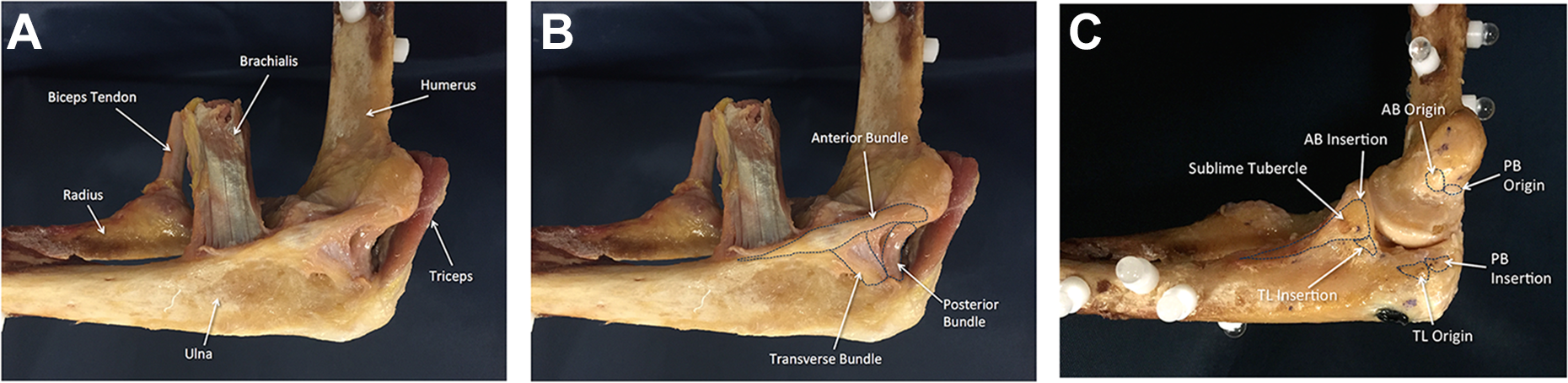
Fully dissected specimens revealing the (A) tendons of the biceps, brachialis, and triceps; (B) medial ulnar collateral ligament complex; and (C) origins and insertions of the anterior bundle (AB), posterior bundle (PB), and transverse ligament (TL).
The elbow was placed in full extension (defined as either 0° of extension or the full limit of extension for that specimen), and the distal forearm was securely clamped in place. The spheres were digitized at 0°, 30°, 60°, and 90° of flexion using a 3D coordinate measuring device (FARO Gage; Faro) mounted with a ball probe tip by the aforementioned digitization method (see the Appendix). 23 With the elbow in 90° of flexion, the ligamentous structures were carefully outlined (Figure 1B). Both the perimeters and surface areas of each ligament (AB [or UCL], PB, and TL) were digitized using a sharp tipped probe. Afterward, they were released in the midsubstance so that the complete outlines of the origins and insertions could easily be identified and digitized. Once the complete outline was identified (Figure 1C), the anatomic center was visually identified and digitized by an orthopaedic surgeon. The accuracy and reliability of this step were assessed using repeated-measures testing; accuracy was consistently found to be within 1 mm. The geometric centroids of each footprint were calculated from the outline of the digitized footprint. When calculating the centroids, points were equally distributed around the perimeter of the footprint to reduce bias. The following bony landmarks were digitized: apex of the medial epicondyle, apex of the sublime tubercle, trochlear margin, ulnar articular margin, and apex of the coronoid.
All specimens underwent CT with 3D reconstruction. Using a technique previously described by Li et al, 23 the digitized ligament anatomy was mapped onto 3D renderings of both the ulna and the humerus for each cadaveric specimen (see Supplementary Video). This method has been previously documented to register the digitized ligament insertions to within 0.59 mm of the 3D renderings of the underlying bone as obtained from CT. 23 Registration of the digitized ligament insertions and the 3D reconstructed bony geometries was accomplished in 6 main steps that are outlined in greater detail in the Appendix.
Data Analysis
The surface area of the origin and insertion of each ligament was calculated from the digitized footprints using the method described by Harner et al. 20 With the elbow at 90°, the surface area was determined for intact ligaments as well as their origin and insertion footprints. The length of the UCL insertional footprint was measured by reporting the maximal distance between the most proximal and distal points of the outline of each footprint.
Statistical Analysis
The outcome measures for the study were surface area of intact ligaments, area of origin and insertion footprints, distance between footprint centers and key landmarks, distance between perceived footprint centers (marked by the investigator during digitization) and geometric footprint centroids, and ligament isometry through an arc of flexion. Means ± SDs, ranges, medians, and 95% CIs are reported for all outcome measures. To assess ligament isometry, the change in distance between the origin and insertion centers of the AB and PB was compared between full extension and the highest degree of flexion assessed (90°) using a paired 2-tailed t test (P < .05).
Results
With a mean overall surface area of 324.2 ± 71.6 mm2, the AB (UCL) was the largest of all of the medial elbow ligament structures (Supplemental Video and Figure 2A), and the mean area of the origin and insertional footprints was 32.3 ± 6.8 mm2 and 187.6 ± 47.3 mm2, respectively (Table 1 and Figure 2B). The mean length of the AB insertional footprint (distance from the most proximal to distal aspect of the footprint) was 29.7 ± 5.4 mm (range, 22.7-40.4 mm; median, 28.2 mm). Additional ligament dimensions are described in Table 1. The TL inserted on the ulna just posterior to the AB; however, it consistently demonstrated a broad insertional expansion that extended proximally onto the AB itself (Figure 2A). The mean overall surface area of the TL was 134.5 ± 31.2 mm2, with an origin footprint of 21.2 ± 9.3 mm2 and a bony insertional footprint of 16.7 ± 7.2 mm2 (not including the portion that inserts directly onto the soft tissue of the AB).

Orientations and areas of the (A) entire ligaments and (B) their origins and insertions for the medial side of the elbow. AB, anterior bundle; PB, posterior bundle; TL, transverse ligament.
Area of Ligament Surfaces, Origins, and Insertions of the Medial Ulnar Collateral Ligament Complex

The distances between the centers of these footprints to key bony and chondral structures are outlined in Figure 3. Most notably, the perceived center of the AB origin was located 11.7 ± 1.4 mm from the medial epicondyle, 13.9 ± 1.7 mm from the trochlear margin, and 5.4 ± 0.9 mm from the center of the PB insertion. The apparent center of the AB insertion (roughly the apex of the sublime tubercle) was 5.9 ± 1.7 mm from the ulnar margin and 7.4 ± 1.5 mm from the center of the bony insertion of the TL. The distance between the apparent center and the actual geometric centroid of each footprint was minimal (range, 0.8-1.3 mm), with the exception of the AB insertion (Table 2). This demonstrated a mean difference of 7.6 ± 2.4 mm between the 2 points (Figure 3A). For the AB insertion, the visual or apparent center was marked at the apex of the sublime tubercle, which at one time was considered to be the center of the insertion. The geometric centroid was consistently distal to the point.
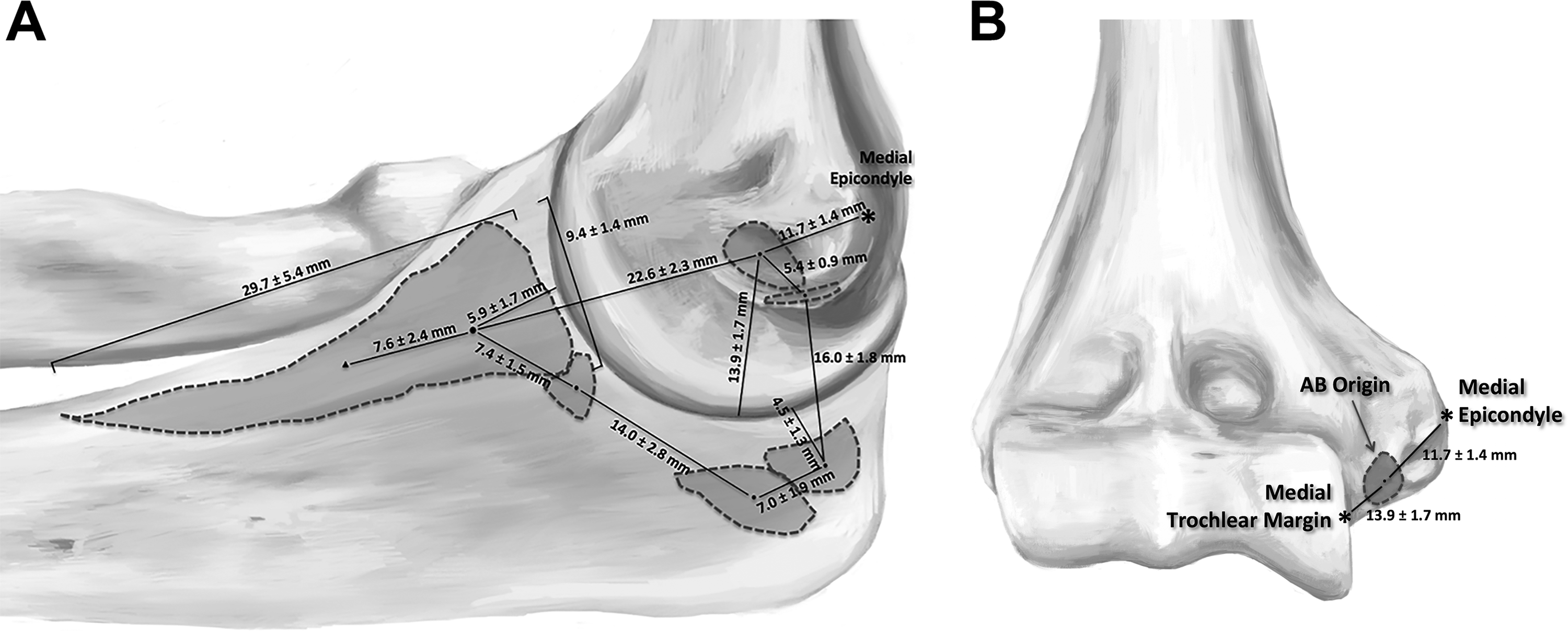
Distances between ligament centers and key bony landmarks when viewing from (A) medial and (B) anterior. The solid circle represents the apex of the sublime tubercle and the apparent center of the footprint, while the solid triangle represents the geometric centroid. AB, anterior bundle.
Distance Between Apparent Centers of Ligament Footprints and Geometric Centroids

The length from the origin to the insertion of the PB did not change significantly from 0° to 90° of elbow flexion (P = .606) (Table 3). This was not the case for the AB, in which the length increased by 2.3 mm (95% CI, 0.01-4.59; P < .001) from the center of the origin to the perceived center and 2.2 mm (95% CI, 1.23-3.21; P < .001) from the center of the origin to the geometric centroid of the insertion (Table 3).
Distance Between Centers of the Ligament Origin and Insertion Footprints at Varying Degrees of Elbow Flexion a
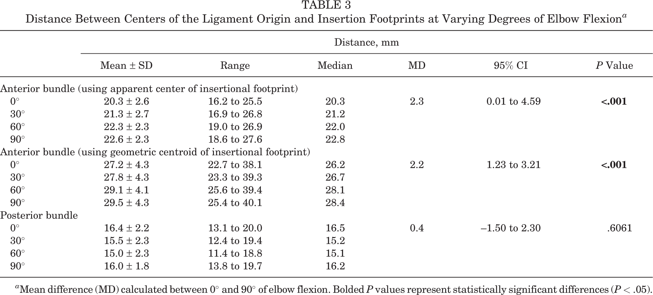
a Mean difference (MD) calculated between 0° and 90° of elbow flexion. Bolded P values represent statistically significant differences (P < .05).
A video has been created that allows rotation of a 3D reconstructed elbow on CT with digitized footprints for all ligaments of the MUCLC (see Supplementary Video).
Discussion
A number of anatomic analyses of the MUCLC of the elbow have presented somewhat conflicting results. 7,14,18,19,25,26,29 Accordingly, the purpose of this work was to utilize 3D anatomic digitization and CT technology to quantify anatomic dimensions of all ligaments that compose the MUCLC, distances to key structures, and isometry through an arc of motion. Ultimately, the AB of the MUCLC demonstrated a mean area of 324 mm2, with a large (187.6 mm2) and elongated (mean length, 29.7 mm) insertional footprint on the ulna. The mean surface areas of the PB and TL were 116.6 mm2 and 134.5 mm2, respectively. For all origin and insertion footprints, the apparent center was within 0.8 to 1.3 mm of the actual geometric centroid, with the only exception being the AB insertion. This centroid was located a mean of 7.6 mm distal to the apparent center (the traditional site for UCL reconstructive procedures). The PB was isometric as the elbow ranged from 0° to 90°, but the length of the AB increased by 2.3 mm as the elbow was flexed to 90°.
One of the more recent studies of AB anatomy, and the only other to use digitizing technology, was published in 2014 by Capo et al. 7 In that work, the mean area of the entire AB was 421 ± 211 mm2, which is larger than what was determined in the current study (324.2 ± 71.6 mm2). These data may be informative for determining appropriately sized grafts during UCL reconstruction. Those authors also reported an insertional footprint area (154 ± 79 mm2) only slightly smaller than that in the current study (187.6 ± 47.3 mm2) (P = .271); however, the geometry differed significantly from that observed in the present work. Specifically, Capo et al 7 did not demonstrate the elongated footprint previously described by Dugas et al 14 and Farrow et al. 18 The current study’s results more closely mirror the findings of these latter 2 studies. In fact, the AB insertional geometry and distance to key structures reported by Dugas et al 14 were quite similar to those in the current investigation, and the same is true for the Farrow et al 18 study, in which the length of the AB insertion was 29.2 mm versus 29.7 mm in the current report. Unfortunately, these latter 2 studies were limited in that they did not report all dimensions of the AB or attempt to analyze the PB or TL to any degree; however, of the variables that they studied, their results were consistent with those of the current investigation.
Looking further at the insertional footprint of the AB, it was the only footprint in which the visual or surgeon-perceived center was not within 0.8 to 1.3 mm of the actual geometric centroid. The perceived center was marked as the apex of the sublime tubercle (based on historical thinking and contemporary surgical techniques) and was generally located 5.9 mm distal to the articular surface of the ulna. This distance was very similar to those reported by Farrow et al 18 (5.8 mm) and Dugas et al 14 (7.8 mm). The current study is unique, however, in that it also determined the geometric centroid of all footprints. For the AB insertional footprint, this centroid was located 7.6 mm distal to the apex of the sublime tubercle. Again, this finding may have novel implications for UCL reconstruction surgery; however, additional investigation is warranted before a change in surgical technique can be recommended.
Regarding the area of the origin of the AB, a large discrepancy exists between the work of Capo et al 7 (mean area, 216 ± 138 mm2) and the current investigation (32.3 ± 6.8 mm2) (P < .001). The current study is more consistent with the findings of Dugas et al, 14 who demonstrated a mean AB origin area of 45.5 mm2. Although the insertional footprint of the AB has historically garnered the most attention, these notable discrepancies for the origin footprint are in need of further investigation, as they may also have implications for surgeons who desire to place grafts in the center of native ligament footprints during reconstruction surgery.
To date, the dimensions and function of the PB and TL remain relatively undefined in the literature (particularly for the TL). This lack of study of the TL may be related to the fact that it is not generally considered to be a significant contributor to elbow stability because it originates and inserts on the same bone. However, an expansive soft tissue insertion of the TL onto the AB was identified in all specimens in this study. Given the orientation and attachment site of these fibers (see Figures 1 and 2), we speculate that the TL may support the AB and provide some resistance to valgus loading. Additional biomechanical investigation into this possibility is needed to determine the significance of this finding, which could have surgical implications.
Finally, another aim of this work was to evaluate the isometry of the AB and PB through an arc of elbow motion. Similar to the original study on this topic by Morrey and An, 25 the length of the AB (defined as the distance between the centers of the footprints) increased by 2.2 mm as the elbow was flexed from 0° to 90° (P < .001). Although the findings of this study do not necessarily support distalizing the ulnar tunnel position during UCL reconstruction, they do suggest that a slightly distalized ulnar tunnel may demonstrate similar graft anisometry to standard graft positioning. Contrary to the work of Morrey and An, 25 the PB remained relatively isometric in the current study (P = .606). One potential explanation for this discrepancy is that the current study only tested the specimens from 0° to 90°, versus 0° to 120° as was done by Morrey and An. 25 This is further supported by the fact that the most significant change in ligament length was noted from 90° to 120° in their study. 25
This study is not without limitations. Namely, although this work provided a detailed analysis of ligament geometry, it does not provide information on ligament volume, fiber orientation, biomechanics, or in vivo function of the elbow. Nevertheless, this study may serve as a foundation for future investigation of the most appropriate locations for ligament reconstruction. Accordingly, these data should be interpreted with caution until additional biomechanical and clinical investigations are conducted. Second, this study is limited in that isometry was only assessed from 0° to 90°. It is possible that greater changes could have been observed with greater degrees of flexion; however, we assessed isometry over a common functional range of the elbow joint in this initial study. Finally, similar to other studies on this topic, this investigation utilized skeletally mature specimens. Accordingly, these data may not be applicable to younger elbows.
Conclusion
This work provides an anatomic quantification and description of the entire MUCLC of the elbow including the AB, PB, and TL. Ultimately, the mean area of the AB was 324 mm2 with an origin footprint of 32 mm2 and an elongated insertional footprint of 188 mm2 (length, 29.7 mm). The geometric centroids of all footprints could accurately be predicted, with the exception of the AB insertion centroid, which was 7.6 mm distal to the apex of the sublime tubercle. While the PB remained relatively isometric from 0° to 90° of flexion, the AB lengthened by 2.2 mm. In all specimens, the TL demonstrated an expansive soft tissue insertion on the AB that, to our knowledge, has not been previously described. These findings may have important implications for medial elbow reconstruction surgery; however, additional investigation is warranted before changes in clinical practice can be recommended.
Footnotes
One or more of the authors has declared the following potential conflict of interest or source of funding: This work was funded by internal institutional funds, including the Hospital for Special Surgery Shoulder and Sports Medicine Research Fund and Surgeon in Chief Fund, the Clark Foundation, the Kirby Foundation, and the Gosnell Family. C.L.C. has received financial or material support from Arthrex. J.S.D. is a paid consultant for Arthrex and ConMed Linvatec, is a paid presenter/speaker for Arthrex, receives research support from Arthrex, receives royalties from Biomet, and receives publishing royalties from Wolters Kluwer Health–Lippincott Williams & Wilkins.
Ethical approval for this study was obtained from the Hospital for Special Surgery (study No. 2015-645-CR1).
APPENDIX
Detailed description of the development and validation of the anatomic digitization and computed tomography (CT) co-registration processes presented in a stepwise fashion. This includes descriptions of specimen preparation, positioning, apparatus setup, and data analysis.
The 3-dimensional (3D) reconstructions of bony geometries of cadaveric elbows obtained from CT scans and the digitized origins and insertions of the ligaments and bony landmarks of each elbow specimen were registered in 6 steps.
First, 6 radiopaque, 0.25 ± 0.0002 inch-diameter borosilicate glass spheres (Hartford Technologies) with 99.99% manufacturer-documented sphericity were rigidly attached to both the ulna and humerus of each specimen (6 spheres for the humerus and 6 for the ulna) such that they were not collinear (Figure A1). 20 To affix the spheres to each bone, 10 polyoxymethylene hex-socket cap screws (Craftech Industries) were screwed into the cortical bone after predrilling and tapping. Ethyl cyanoacrylate (Krazy Glue; Elmer’s Products) was administered to the threads of each screw before fixation in the bone to prevent loosening. Each screw was rotated until its head was flush with the cortical bone. After each screw was 2-finger tightened, ethyl cyanoacrylate was again used to secure a sphere on top of the socket cap of each screw, similar to the technique described by Araki et al. 3
Second, each specimen was scanned using CT (Biograph; Siemens) with a 0.6-mm slice thickness and 0.5 × 0.5-mm2 in-plane pixel dimensions (settings: 140 kV and 140 mA).
Third, the 3D geometries of the bones and spheres were reconstructed using image processing software (Mimics; Materialise). The humerus, radius, and ulna were segmented by using grayscale thresholding (settings: Hounsfield unit range, 230-3071). The spheres were also segmented via grayscale thresholding (settings: Hounsfield unit range, 480-3071), and the centroid of each resulting spherical geometry was identified in the reference frame of the CT scanner (Figure A2). A 6.35 mm-diameter sphere, consisting of 40,000 evenly distributed vertices, was then created and centered on each of the previously identified centroids.
Fourth, the humerus of the cadaveric specimen was fixed to a stationary base, and the distal forearm was attached to an adjustable fixture that allowed the elbow to be fixed at various flexion angles. In this study, the elbow was fixed at full extension and 30°, 60°, and 90° of flexion. The glass spheres were then identified using a 3D coordinate measuring machine (ie, digitizer) (FARO Gage; Faro) with a ball probe tip (diameter: 5.998 mm) at each of these flexion angles. This configuration of the digitizer had a manufacturer-reported accuracy of 0.018 mm. The center of each sphere was identified by digitizing 12 points on the surface of each sphere (Figure A3). This number of points reduced variations in the location of the sphere center to ≤0.01 mm, which was adequate for the present study. A 6.35 mm-diameter sphere with 40,000 evenly distributed vertices was then generated and located on the centroid of each digitized sphere in the reference frame of the digitizer.
Fifth, the soft tissue insertions and bony landmarks were digitized using a point probe with a manufacturer-reported accuracy of 0.018 mm (Figure A4). The anatomy was digitized with the elbow fixed at 90° of flexion. Before conducting the digitizations, screws were placed across the ulnohumeral joint and radiocapitellar joint to provide additional stability to the joint and to supplement fixation of the proximal humerus and distal forearm (Figure A5). This additional fixation was needed because trial dissections revealed that the elbow became unstable during digitization as the capsuloligamentous structures were sequentially released. The utilization of these supplemental screws eliminated motion across the ulnohumeral and radiocapitellar joints after releasing the capsuloligamentous structures. Each ligament was carefully outlined using a surgical marker (Aspen Surgical Products). Both the perimeters and surfaces of each ligament were then digitized. Afterwards, the ligaments were released at their midsubstance so that the complete outlines of their origins and insertions could be identified and digitized. Once the complete outlines were identified, the visual center was digitized. The following bony landmarks were also digitized: apex of the medial epicondyle, apex of the sublime tubercle, trochlear margin, ulnar articular margin, and apex of the coronoid.
Sixth, to register the digitized anatomic landmarks to the 3D bony geometries obtained from CT, the iterative closest point algorithm available in reverse engineering software (Geomagic Studio; 3D Systems) was used to match the sphere geometries obtained from CT (step 3) to the sphere geometries obtained from digitization (step 4) at each flexion angle that the elbow was fixed (Figure A6). To register the anatomic points digitized at 90° of flexion to the bone geometries at the other flexion angles, the iterative closest point method was again used. All of the digitized landmarks were within 0.5 mm of the reconstructed bony surfaces using this registration method (Figure A7).
References
Supplementary Material
Please find the following supplemental material available below.
For Open Access articles published under a Creative Commons License, all supplemental material carries the same license as the article it is associated with.
For non-Open Access articles published, all supplemental material carries a non-exclusive license, and permission requests for re-use of supplemental material or any part of supplemental material shall be sent directly to the copyright owner as specified in the copyright notice associated with the article.