
Abstract
Stable, anatomical fixation of acetabular fractures gives the best chance of successful outcome, while penetration of the acetabular articular surface with screws is associated with poor outcomes. Spring plates are an alternative to interfragmentary lag screws when penetration is a concern. A mechanical study comparing fracture stability and construct stiffness of three fixation methods for posterior wall acetabular fractures with transverse comminutions was performed. The three fixation methods tested were a posterior wall rim plate, a posterior wall buttress plate with separate lag screws and a posterior wall plate with two spring plates. Nine samples were tested, three for each fixation method. Two-dimensional motion analysis was used to measure fracture fragment displacement and construct stiffness. After two 6000 cycle-loading protocols, to a maximum 1.5 kN, the mean fracture displacement was 0.154 mm for the rim plate model, 0.326 mm for the buttress plate and 0.254 mm for the spring plate model. Mean maximum displacement was significantly less for the rim plate fixation than the buttress plate (p = 0.015) and spring plate fixation (p = 0.02). The rim plate was the stiffest construct 10,962 N/mm, followed by the spring plate model 5637 N/mm and the buttress plate model 4882 N/mm. Based on data obtained in this study, where possible a rim plate with interfragmentary lag screws should be used for isolated posterior wall fractures as this is the stiffest and most stable construct. When this method is not possible, spring plate fixation is a safe and a superior alternative to a posterior buttress plate method.
Introduction
Posterior wall fractures represent the third most frequent type of acetabular fracture (adults < 60 years) and fourth most frequent (adults > 60 years). 1 –3 Anatomical fixation of the posterior wall in displaced acetabular fractures is important to restore joint stability, decrease the risk of degenerative arthritis and reduce poor functional results. 3,4 Techniques for fixation involve both plate and screw fixation or combinations 5 thereof. The close proximity of the articular surface on the posterior wall fragments means it can be difficult to obtain fixation due to the risk of joint penetration 6 or comminution of the fracture when inserting a screw. These difficulties have led to the use of spring plates. The spring plate is a pre-contoured, one-third tubular plate with a hooked end, when it is applied the two hooks engage the non-articular cortical surface of the fracture fragment. It is secured to the posterior column with one or more cortical screws and can be reinforced by buttressing with an overlying reconstruction plate. Multiple spring plates can be used. The use of spring plates avoids the risk of joint penetration and of further comminution of the fragile fracture fragments.
There are comparatively few mechanical studies comparing acetabular fixation methods. A previous biomechanical study of posterior wall fractures compared the use of reconstruction plate with or without spring plates in concentrically comminuted (CC) fractures and the use of lag screws with or without reconstruction plate in transversely comminuted (TC) fractures. 6
The aim of this study was to perform a mechanical assessment to identify any difference between three commonly used fixation methods for isolated posterior wall acetabular fractures (AO/OTA 62.A1) 7 with regards to total fracture displacement and construct stiffness.
Materials and methods
Nine large, left, fourth-generation composite bone Sawbones© hemi-pelvises were used to create the models. 8 A crescentic posterior wall fracture was created in each hemi-pelvis, which was then bisected to simulate transverse comminution (Figure 1). The fractures were created in a reproducible fashion using a circular saw with a diameter of 50 mm mounted on a pillar drill. Each crescentic fracture fragment was further sectioned using a band saw to give two fracture fragments of equal size. The maximum posterior extension of the intact crescent-shaped fracture into the posterior wall was 20 mm; the distance from tip to tip was 48 mm. A postero-superior fracture was produced, and the most superior fragment was used for testing. Other studies have shown that the biomechanical effect of loading the superior-posterior wall of the acetabulum is much greater than that of the inferior wall of the acetabulum. 9
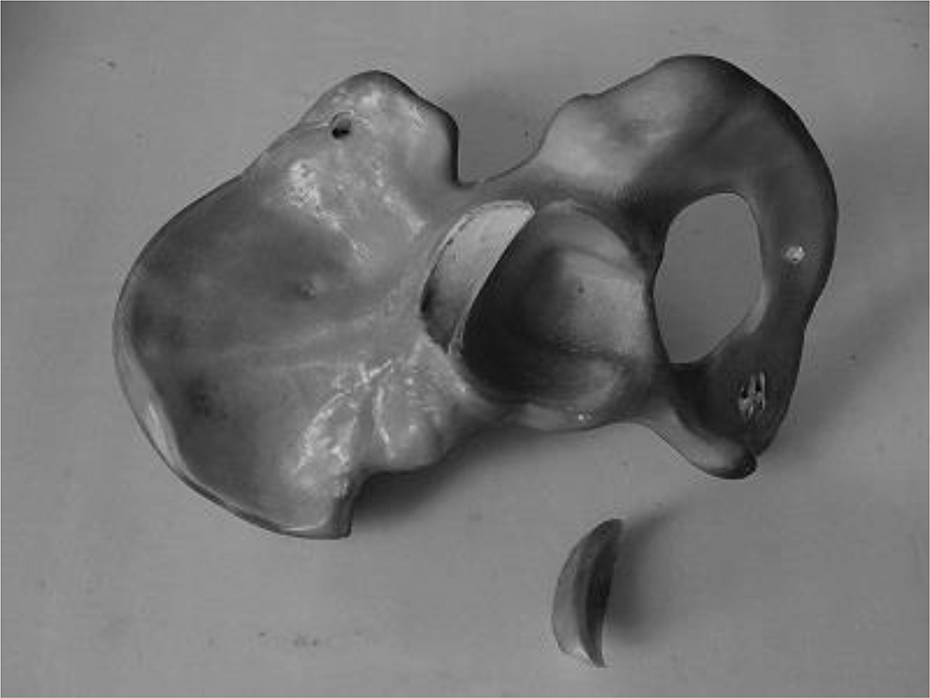
Pelvis with fracture.
The hemi-pelvis was mounted in Woods metal such that a plane encompassing the anterior superior iliac spine and the anterior symphysis pubis was vertical and the joint surface of the symphysis pubis was also vertical at 90° to this plane. An angle plate (a work holding device preventing further movement or distortion) was used to produce 30° flexion during cyclic loading to simulate hip flexion on maximal loading during the gait cycle. 9 During pretesting of the model, measurements of displacement were made in the anatomical coronal and sagittal planes. This showed that the greatest displacement occurred in the coronal plane, so this was the plane chosen to study for analysis. A reproducible and measurable axial load was produced using a servo-hydraulic material testing machine (Instron 8511, Shimadzu UK, Buckinghamshire, England). This force was applied through a 56-mm diameter hemi-arthroplasty head, whose taper had been adapted to fit the actuator of the testing machine was used to transmit the force created by the load cell to the inner aspect of the acetabulum (Figure 2).

Setup broad view.
The three fixation methods were tested using three models for each method (Figure 3): Rim plate method: Two lag screws were inserted through a contoured plate that is positioned on the lateral rim of the acetabulum. Buttress plate method: Two lag screws used to fix the fracture fragments were inserted peripherally and a contoured plate was positioned medial to the lag screws buttressing the fracture fragments Spring plate method: Two spring plates were each held with one 3.5-mm diameter cortical screw applied through their distal hole and secured with an overlying buttress plate.

Graphical representation of fixation methods.
The small fragment reconstruction plates used for all these methods were identical 10-hole (3.5-mm diameter) plates (Synthes, Hertfordshire, UK) that were contoured prior to application. This was performed using large plate benders by a consultant orthopaedic surgeon specialized in pelvic reconstructive surgery. To eliminate variability in this step, for each method of fixation, one plate was used and this was removed and re-applied to the next model in-between each test. To ensure that the testing protocol was not deforming the plate, a cast of the plate was made in dental cement and its shape confirmed visually between each test. The spring plates used were made from one-third tubular plates, produced by the hospital medical engineering department, as previously described. 10,11
Real-time measurement of the displacement of the fracture fragments was recorded in two dimensions using a digital camera Allied Technology Marlin F-201B vision system. 12 The digital images were recorded using LabView software with the vision assistant suite. To measure displacement, markers were placed on the bones; black dots on a white background. The marker on the fragment was positioned 2 mm inferior to the acetabular rim and 2 mm lateral to the central split in the crescentic fragment. The marker on the pelvis was positioned 2 mm inferior to the posterior edge of the fracture in the same plane as the fracture fragment marker. The vision system measured the circle centre position of the reference image and the centre coordinate was stored; subsequent images were then analysed against this reference. The software converted further images of the markers into a value of the markers’ position relative to the reference image. Computation of fracture displacement was performed by the LabView software at the end of each image acquisition cycle. A split signal from the Instron machine was used to record actuator position and applied force during all tests.
The visions system has been validated for the purpose of biomechanical testing of fracture fragments and is considered to have an accuracy of 0.2 mm and measurement resolution of 0.02 mm with a circular visual marker and is thus suitable for the purposes of this study. For small displacements comparable to those expected during biomechanical experimentation (i.e. <5 mm), a very low standard deviation was achieved between the true actuator and vision system displacement measurements at just 0.024 mm. At a confidence level of 99.7%, the vision system therefore has a measurement accuracy of 0.144 mm. As such, it is considered that a conservative estimate of the system’s measurement accuracy is ±0.2 mm. 13
Once started, the software acquired real-time images after every 200 cycles. Thirty images are then recorded at the maximum acquisition frequency of the camera (15 Hz) representing 1–2 complete sinusoidal waveforms depending on the frequency of the loading protocol.
A test protocol of 6000 load cycles at range1 kN followed by 6000 cycles at range 1.5 kN was chosen to test the models. A frequency of 1 Hz was chosen to represent the cyclic loading during the gait cycle. Approximately 6000 cycles represent 3 h 20 min of continuous walking and were chosen to simulate early post-operative rehabilitation. The force of 1.5 kN was used as an estimate of maximal load through the hip joint of 2–3.5 times body weight during single-leg stance of an average person. 9
Following 6000 cycles at 1 kN and 6000 cycles at 1.5 kN, all models had measurements taken for 10 full cycles at 1.5 kN at a cycle frequency of 0.5 Hz. Slowing the loading cycle ensured that the camera captured the point of maximum displacement. Although slowing the rate of loading in a viscoelastic material (Sawbones or bone) may increase displacement, this was not seen when comparing the first two 6000 cycles with the subsequent ten 6000 cycle results.
The maximum and minimum total displacement for each cycle was extracted from the data and vertical and horizontal displacement components were calculated, along with the baseline displacement. Mean displacement over the 10 cycles was then calculated.
An exploratory data analysis was performed to determine the appropriate method of statistics analysis. All the models’ data sets were considered sufficiently normally distributed to allow parametric data analysis. Independent t-tests were performed on the mean maximum displacement for each fixation type.
Force–displacement values were plotted from the first half of the hemi-sine wave generated by the actuator for the waveforms of the 10 cycle results (baseline to maximum displacement). A linear regression analysis was performed to estimate the slope of the correlation and therefore the construct stiffness in N/mm. This analysis was completed for each of the waveforms to produce 10 estimates of construct stiffness for each model. The mean construct stiffness for each model was used to calculate the mean construct stiffness for the fixation type.
Results
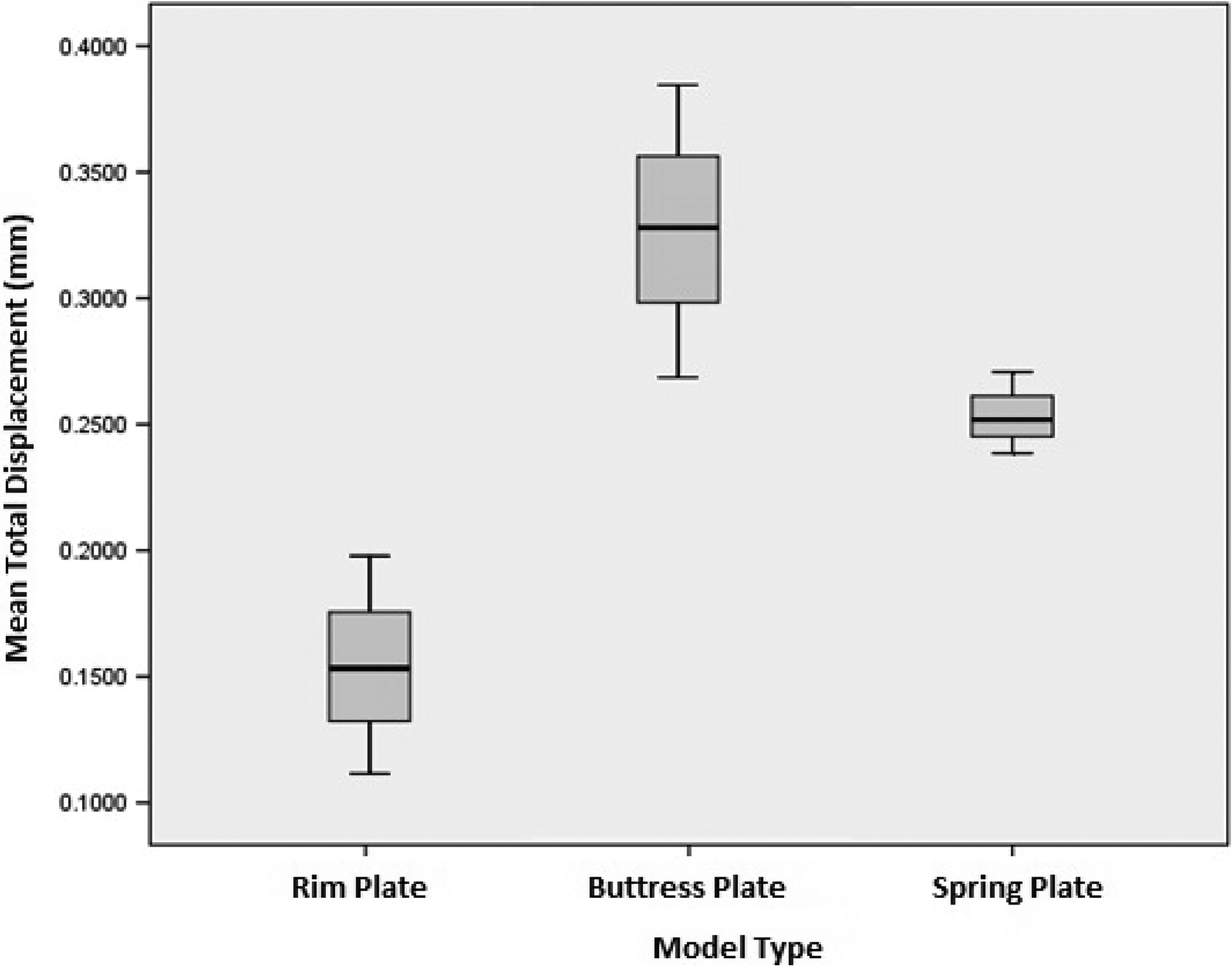
Table 1 presents the mean fracture gap under 1.5 kN load following the testing protocol, as shown in Figure 4. Comparison of fixation methods showed that the rim plate had significantly less displacement compared to both the buttress and spring fixations. There was also less displacement of the spring plate model compared to the buttress model though the difference was not significant (Table 2).
Mean total displacement of fixation methods.

SD: standard deviation; SEM: standard error of mean.
Mean total displacement of fixation methods.
Comparisons of fracture displacements for three fixation methods.

CI: confidence interval.
When comparing the mean stiffness of each construct, the rim plate was the stiffest, followed by the spring plate and buttress techniques (Table 3) (Figure 5). There was significant difference between the mean construct stiffness of the rim plate and buttress plate fixation, though there was no significant difference between the rim plate and the spring plate, or the spring plate and the buttress plate (Table 4).
Construct stiffness of fixation methods.

SD: standard deviation.

Mean construct stiffness.
Comparisons of stiffness for three fixation methods.

CI: confidence interval.
Discussion
The data presented suggest that there is a significant difference in the construct stiffness and the fracture displacement on cyclic loading between fixation with lag screws applied through a plate and lag screws independent and anterior to a plate. Fracture displacement was significantly more in the spring plate model compared with lag screws through a plate; however, this did not translate to a significant difference in overall construct stiffness.
Posterior wall fractures of the acetabulum are challenging to treat. Accurate anatomical reduction has been shown to improve the outcome of these injuries. Predictors of poor outcome include non-anatomical reduction, marginal impaction, femoral head chondral injuries and labral injuries; predisposing to radiological arthritis and poorer functional performance. 14 –17
One of the most challenging aspects of this surgery is positioning a lag screw through a small fracture fragment while controlling the angle of advancement, so that the joint is not penetrated. 18,19 Several techniques of fixation in widespread use have different theoretical advantages. In this study, three of the most commonly used techniques were assessed: rim plate, buttress plate and spring plate.
The rim plate has the advantage of being the most mechanically sound construct; however, it is also the most technically demanding with the highest potential of joint penetration from screws. During this study, there was no joint penetration by the lag screws put through the rim plates and this is likely due to the optimum exposure afforded by a Sawbones model.
The buttress plate method is easier to perform since the lag screws used to secure the fracture do not need to be placed through the plate making it easier to direct them away from the joint. Fragment-specific stabilization using a spring plate for a TC posterior wall fracture is comparatively straightforward. This technique provides a secure and precise fixation with a reduced risk of joint penetration from screws, as these are located well away from the joint. There is a small additional risk of fragment resorption or penetration leading to direct contact between the hooks and the chondral surface of the femoral head.
There have been few mechanical studies comparing fixation methods of posterior wall fractures. A study using similar methods reported on cadaveric specimens. 5 In this study, 10 cadaveric specimens (aged 27–87 years) had two types of fracture created in their posterior walls: TC and CC. The TC fractures were fixed with either lag screws alone or lag screw through a plate. The CC fractures were fixed with either a reconstruction plate alone or reconstruction plate with spring plates. These constructs were then constantly loaded, and fracture displacement measured, in relation to load applied, to a maximum fracture gap of 2.5 mm. The constructs were also tested to failure. The results of this study showed that lag screws through a plate were both significantly stiffer and stronger (failed at a higher load) than the lag screws alone. Similarly, the addition of spring plates to the reconstruction made the construct stiffer and stronger.
Another cadaveric biomechanical study comparing fixation methods 20 found no significance in displacement between three methods (two lag screws alone, two screws with reconstruction plate and two screws with locked reconstruction plate). However, testing was only performed over six cycles of 1500 N.
Further studies have reported on posterior wall fixations with one looking at novel fixation techniques and only reported load at mechanical failure, 21 and the other on the use of calcium phosphate cement. 22 Other Sawbones studies have not looked at hook plate constructs. 23
Limitations of the study include the fracture model using Sawbones and not on human bone. The number of models tested for each model was limited to three. Having only three specimens in each group is an obvious limitation for statistics analysis; however, financial constraints made a larger study unfeasible. The test was of primary stability using a simulated cyclical walking gait and the forces could be different for other activities, such as sitting, which may confer increased forces across the posterior wall. Furthermore, the effect of the soft tissue including the posterior capsule could not be assessed. The models were mounted rigidly in a potting system angulated to simulate the point of maximum loading during the gait cycle (heel strike). Alternative more physiological methods of mounting the pelvises at points representing the symphysis pubis joint and the sacroiliac joint may have allowed more realistic displacement within the hemi-pelvis. 24
The results represent the first mechanical study where the behaviour of fixation constructs for posterior acetabular wall fractures has been examined over prolonged cyclic loading protocols, chosen to represent the early post-operative phase. The use of composite bone Sawbones confers the advantage of consistent material properties that cadaveric material does not. The study shows that there is a significant difference in the construct stiffness and fracture displacement between the rim plate method and the other two fixation methods. Historically, this construct was identified to be clinically superior. 1 When comparing the other two fixation methods, the spring plate fixation method showed less fracture displacement and higher construct stiffness than the buttress plate method although that was not statistically significant. The stiffness of the spring plate was also not significantly different from that of the rim plate method.
The overall differences between the models were small and therefore not likely to be clinically significant. This study supports the adequacy of a spring plate as fragment-specific stabilization, where a lag screw through a contoured rim plate cannot be achieved. This study has shown that either the use of spring plate or a buttress plate method are safer alternatives with good biomechanical properties, with the spring plate method having a better biomechanical profile than that of the buttress plate.
This was a small study that was financially constrained. It was not possible with the limited resources to look at all variations of fragment fixation, the numbers of composite Sawbones bone models for each fixation method were also small with only three in each group. A comparison between the positioning of the lag screws, being placed laterally or medially to the buttress plate, was not attempted because of the small number of hemi-pelvis available to the study. Loading to failure was not performed on all models in the study. During the pilot study, one model was put through a protocol to examine load to failure. The construct failed at applied force of 13.19 kN. During this test, mechanical failure (defined as the point where the compressive force versus displacement curve is no longer linear) occurred before “clinical failure” (a fracture gap of 2 mm). The way in which composite saw bone fails is arguably less representative of normal bone than simple cyclical loading protocols. In this study, the aim was to recreate the mechanical conditions placed on the fixation during the early rehabilitation period. In order to show differences between the mechanical properties of the different fixation constructs, non-physiological loading protocols may better show this.
Footnotes
Authors’ note
Research completed at Department of Mechanical Engineering, Centre for Orthopaedic Biomechanics, University of Bath, Bath BA2 7AY, UK.
Declaration of conflicting interests
The author(s) declared no potential conflicts of interest with respect to the research, authorship and/or publication of this article.
Funding
The author(s) received no financial support for the research, authorship and/or publication of this article.