
Abstract
Objective:
To investigate the effectiveness and accuracy of internal fixation of calcaneal fractures with a three-dimensional (3-D) printing navigation module via the sinus approach.
Methods:
Eleven lateral lower extremity specimens were used in the experiment and divided into the digital design (DD) group (n = 11) and the real surgery (RS) group (n = 11). For the DD group, thin-section computed tomography (CT) scans, virtual fracture modeling, virtual bone plate fixation, sinus occlusal module design, and navigation module design were performed for the cadaver specimens. A 3-D navigation module was printed using a 3-D printer. For the RS group, the sinus approach incision was made, and the navigation module was used to assist the placement of screw fixation and anatomically locked bone plate fixation. Thin-layer CT scans, 3-D reconstructions, and reconstruction of the nail paths were performed in the RS group and 3-D registered with the DD group. 3-D coordinate values for the screw entry and exit points in the RS and DD groups were recorded, and the corresponding offset values of the screw points were calculated. The number of qualified nails at different accuracy levels was counted. The χ 2 test was used to compare the data for the DD and RS groups to obtain the accuracy level for both groups when p > 0.05, which is the critical value for experimental accuracy.
Results:
A total of 11 bone plates were placed and 120 screws were locked. None of them protruded from the inferior articular surface. The screw entry and exit point offsets were 1.71 ± 0.11 mm and 3.10 ± 0.19 mm, respectively. When the accuracy requirement for the entry point was 3.8 mm, there was no statistically significant difference between the two groups (p > 0.05). Similarly, the accuracy of the exit point of the screw could only reach 6.6 mm.
Conclusion:
Internal fixation of calcaneal fractures via the sinus tarsi approach with an anatomical locking plate based on the 3-D printing navigation module can achieve accurate screw placement and good overall internal fixation.
Introduction
Treatment of severe calcaneal fractures such as Sanders type III and IV fractures remains challenging. 1 The requirements for calcaneal fracture fixation are extremely strict. Such fixation requires not only anatomical reduction of the calcaneal height, width, length, subtalar articular surface, and the position of the posterior heel tubercle 2 but also accurate and stable internal fixation after fracture reduction to facilitate early rehabilitation exercise. 3
The classical approach for calcaneal fracture surgery is the lateral L-shaped approach, 4 but the incidence of postoperative complications such as incision dehiscence, flap necrosis, and infection remains high. 5 The sinus tarsi approach is minimally invasive, with only a small incision created for calcaneal fracture fixation, which is suitable for most types of calcaneal fractures such as Sanders II and Sanders III, 6 and the incision-related complications are lower than those with the lateral L-type approach. 7 However, because of the small incision and the use of small bone plates, 8 the biomechanical properties of the sinus approach for the treatment of complex calcaneal fractures are inferior to those of the lateral L-type approach. 9 Moreover, achieving minimally invasive incisions with precise and strong internal fixation is still challenging for orthopedic surgeons. Thus, using anatomical locking bone plates via the sinus approach is a promising alternative.
This study designed a three-dimensional (3-D) printing navigation module to assist in the accurate internal fixation of calcaneal fractures using an anatomical locking bone plate via the sinus approach. The results demonstrated the accuracy of orthopedic internal fixation using this technique.
Materials and methods
Experimental specimens
Eleven lower limb specimens of adult antiseptic cadavers were provided by the Department of Anatomy of the Southern Medical University. The anatomical experiment was approved by the ethics committee of our hospital. Specimens were divided into the digital design (DD) group and the real surgery (RS) group.
The following hardware was used: Zortrax M200 3-D printer (Zortrax, Poland), double-threaded linear calcaneus locking plate 11, and a diameter of 3.5-mm locking screws 120 pieces (Dabo, China).
Thin-sampling computed tomography (CT) (Philips/Ingenuity CT, Philips, the Netherlands) scans of cadaveric specimens were performed under the following conditions: voltage 100 kV, current 175 mA, pitch 0.5 mm, layer thickness 1 mm; thin-layer CT scan of bone plates, conditions: voltage 120 kV, current 300 mA; pitch 0.3 mm, layer thickness 0.65 mm. Dicom format image data were acquired through the PACS system (Shenzhen Annet Information System Co., Ltd).
Digital design
Production of standard bone plates
In the DD group, the Dicom format image was output to Mimics 14.0 (Materialise, Belgium) and the threshold setting, region growth, and 3-D reconstruction were as described in Zhang et al. 10 –12 A 3-D digital model of the locking plate with screws is shown in Figure 1(a, panel a1). The main steps for standard plate production included (1) construction of a ϕ1.5-mm, 6-mm-long cylindrical screw channel with MedCAD\Create Cylinder (Figure 1(a, panel a2)); (2) copying of the above screw channel and modification of its diameter in CAD Objects\Properties to 5 mm and removal of the screws used in the 3-D model (Figure 1(a, panel a3)); and (3) merging of the bone plate and the screw channels with the Simulation\Merge as standard components (Figure 1(a, panel a4).
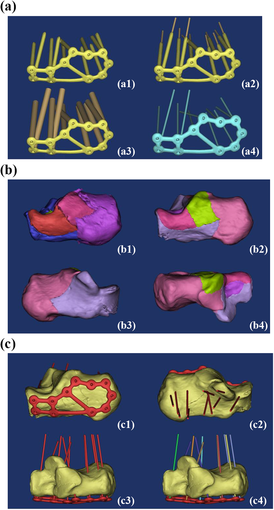
(a) Preparation of standard anatomical calcaneus locking plate: (a1) 3-D model of the bone plate; (a2) preparation of screw channel; (a3) copy and enlarge the diameter of the screw channel; and (a4) standard bone plate parts. (b) Virtual fracture modeling: (b1) Sanders type IV calcaneal fracture and (b2–b4) virtual fracture modeling. (c) Virtual internal fixation: (c1–c3) adjustment of the bone plate and screw channel and (c4) decomposition of standard parts. 3-D: three-dimensional.
Virtual fracture modeling
Virtual fractures based on actual Sanders IV calcaneal fractures were modeled in Mimics. In the 3-D edit box of Segmentation\Edit Mask in 3-D, fracture fragments were segmented from different perspectives by Lasso and separated into individual Masks and reconstructed in 3-D as described and improved in Chen et al 10 (Figure 1(b)).
Virtual internal fixation
The standard part was input into Mimics 14.0 (Materialize) in STL format, and the standard part was moved to the lateral wall of the calcaneus with Move and Rotate. The main points of internal fixation were (1) fracture fragments were well fixed; (2) a screw should not penetrate through the subtalar articular surface; (3) the key screw channel should penetrate through the sustentaculum tali; and (4) the bone plate should be kept 2 mm away from the lateral side of the calcaneus, without sinking into the bone surface (Figure 1(c)).
Design of the navigation module
The sinus tarsi module design was carried out mainly through the following steps: (1) output the calcaneus model to Geomagic Studio 2012 (Geomagic, Inc., Cary, North Carolina, USA) in STL format and thicken it to 2.5 mm (Figure 2(a, panels a1–a2)); (2) other thickened calcaneus model to Mimics in STL format (Figure 2(a, panel a3)); and (3) perform 3-D cutting of the model using Simulation\Cut Orthogonal to Screen from different directions to obtain the card module with multidirectional card biting effect (Figure 2(a, panel a4)).

(a) Card module design: (a1–a2) Geomagic thickening; (a3) thickened calcaneus and original calcaneus; and (a4) multipositioning module. (b) Design of free curve: (b1) decomposition of the screw channel; (b2) removal of the screw channel away from the skin surface along its own axis; (b3) screw support column design; and (b4) drawing of the free curve.
The steps for free curve design were as follows: (1) determine the key screw channel: decompose the screw channel with Simulation\Split (Figure 2(b, panel b1)) while keeping the screw path below the subtalar articular surface. The “key screw channel” was defined as the screw channel that penetrates out of the sustentaculum tali; (2) pull the key screw channel axially away from the bone surface: in the Move operation, select the Inertia axis option, move the screw along its own axis until about 40 mm from the skin (Figure 2(b, panel b2)); (3) for the screw support column design, enlarge the screw channel using the Simulation\Rescale Object five times to obtain a 7.5-mm screw diameter support column as shown in Figure 2(b, panel b3); and (4) draw the free curve of the connection block module and the screw support columns with the MedCAD\Create Spline command (Figure 2(b, panel b4)).
The free curve was converted to a connecting rod and exported as an IGES file to SolidWorks 2011 (Dassault Systems SA, France) to build a datum plane. A 12-mm diameter circle was drawn on the datum plane to obtain a 12-mm diameter connecting bar by scanning and stretching (Figure 3(a)).

(a) Conversion from free curve to connecting rod: (a1) reference plane design; (a2) 12-mm diameter sketch drawing; (a3) scanning and stretching; and (a4) connecting rod entity. (b) Navigation module: (b1–b3) navigation module design and (b4) 3-D printing navigation module.
To design the Navigation module, the connecting rod was exported from SolidWorks back to Mimics as an STL file, which coincides with the original free curve in parallel. Boolean operations (connecting rod + card module + screw support column) − (calcaneo + screw channel) was implemented to obtain the navigation module (Figure 3(b, panels b1–b3)). The navigation module was output to the ZSuite production print file in the STL format for 3-D printing using the 3D Printing Software ZSuite (Zortrax, Poland; Figure 3(b, panel b4)).
Realistic surgery
Internal fixation was conducted via the sinus tarsi approach in the RS group. The lateral sinus approach and the medial sustentaculum tali were marked (Figure 4(a, panels a1–a4)). An approximately 3.5-cm-long incision was made approximately 1 cm from the tip of the tibia to the fourth base of the tibia. The skin, subcutaneous tissue, and long sacral muscles were sequentially exposed. The periosteum dissection device was used closely along the lateral wall of the calcaneus to fully liberate the soft tissue. The fat pad near the sustentaculum tali was removed to expose the subtalar articular surface and the anterior lateral wall of the calcaneus. Care was taken while cleaning to not damage the short extensor muscles and the intercalcaneal ligament.
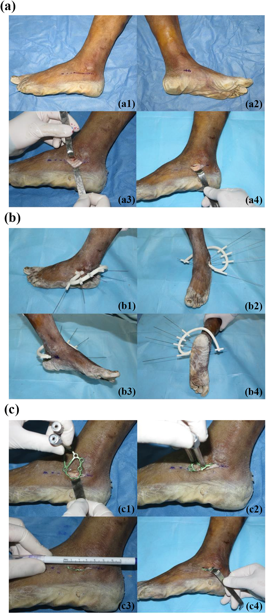
(a) Sinus approach: (a1) marking of the sinus tarsi approach; (a2) marking of the sustentaculum tali; (a3) revealing the sacral muscles; and (a4) exposing the tarsi sinus. (b) Placing navigation module and drilling into the K-wire. (c) Inserting the bone plate and completing the internal fixation: (c1–c3) insert the locking guide as a lever into the plate and (c4) complete the internal fixation.
After the navigation module was well-positioned, a 1.2-mm diameter Kirschner wire (K-wire) was inserted into the screw support columns to observe the positional relationship between the K-wire and the sustentaculum tali on the medial side of the calcaneus, and the position of the navigation module was finely adjusted to obtain the best position and navigation effect. A surgical drill was used to insert the K-wire into the calcaneus, break the navigation module, and exit along the K-wire (Figure 4(b)).
After exiting the navigation module, a 2.8-mm diameter hollow drill was used to drill along the K-wire and remove the K-wire. The locking guide was used as the operating rod to place the bone plate on the lateral wall of the calcaneus, and the position of the bone plate was adjusted according to the drilled hole. A sounder was used to measure the depth, and a 3.5-mm diameter locking screw was installed. The other screws in the locking plate were drilled after cutting open the skin (Figure 4(c)).
3-D registration and experimental data collection
Thin-slice CT scans and 3-D reconstructions were performed on RS specimens. The methods were the same as above. The internal fixation effect is shown in Figure 5(a, panels a1–a2). 3-D registration and experimental data acquisition were carried out as described previously. 10 –12

(a) Internal fixation effect and 3-D registration: (a1–a2) RS internal fixation effect; (a3) preparation of RS screw channel and (a4) RS and DD 3-D registration. (b) 3-D coordinate extraction of the entry and exit points in the RS and DD groups: (b1) comparison of internal fixation between the RS and DD groups; (b2) intrastromal screw channel in DD group; and (b3–b4) entry and exit points in the DD group (green) and RS group (red). 3-D: three-dimensional.
Image registration for the DD and RS groups
The steps for image registration were to (1) construct a 1.5-mm diameter postoperative screw channel with MedCAD\Create Cylinder (Figure 5(a, panel a3)) and (2) combine the postoperative screw channel with the calcaneus with the Merge command and export the STL format file to the DD mask. The Registration\Global Registration operation completed the 3-D registration of RS and DD images (Figure 5(a, panel a4)). The location of the RS and DD bone plates is shown in Figure 5(b, panel b1).
3-D coordinate extraction of screw entry and exit points in RS and DD groups
For 3-D coordinate extraction, the steps were the following: (1) Reconstruct the RS and DD intrastromal screw channels: Boolean operations were performed twice to reconstruct the Minus screw channel and the Intersect screw channel of the calcaneus (Figure 5(b, panel b2)). (2) Position the screw entry and exit points in the RS and DD groups. The MedCAD\Create Point command was used to set the midpoint of the exposed part of the internal bony screw hole (Figure 5(b, panels b3–b4)). (3) Export the 3-D coordinate values for the entry and exit points of all samples in the RS and DD groups using the Export TXT method.
Calculation of offset values for screw entry and exit in RS and DD groups
The offset values for screw entry and exit points were defined as the spatial distances between them in both RS and DD groups. If the 3-D coordinates of the preoperative screw points were set as X1, Y1, and Z1, and the 3-D coordinates of the postoperative screw points were X2, Y2, and Z2, then the offset values of the entry and exit points of RS and DD could be calculated as described previously and simplified. 10 –12
To calculate the number of qualified nails, the screw entry and exit point offset values for the RS and DD groups were filtered from 1.1 mm to 10 mm using a statistical formula (COUNTIF) embedded in Excel at every 0.1-mm interval, and the qualified and unqualified screw points under different accuracy requirements were counted.
Statistical analysis
The entry and exit points of qualified nails in the RS and DD groups were compared using four-squared χ 2 test in SPSS 13.0 (SPSS, Inc., Chicago, Illinois, USA), and p > 0.05 was considered not significantly different.
Results
Evaluation of screw positioning effect
A total of 11 bone plates were placed, and 120 screws were locked. No screws passed through the inferior articular surface. The entry point offset value was 1.71 ± 0.11 mm (0.12–5.85 mm), and the offset point value was 3.10 ± 0.19 mm (0.24–8.76 mm). Figure 6 shows the corresponding number of qualified screws (y-axis) at different accuracy levels (x-axis), where the red curve is the entry point and the blue curve is the exit point.
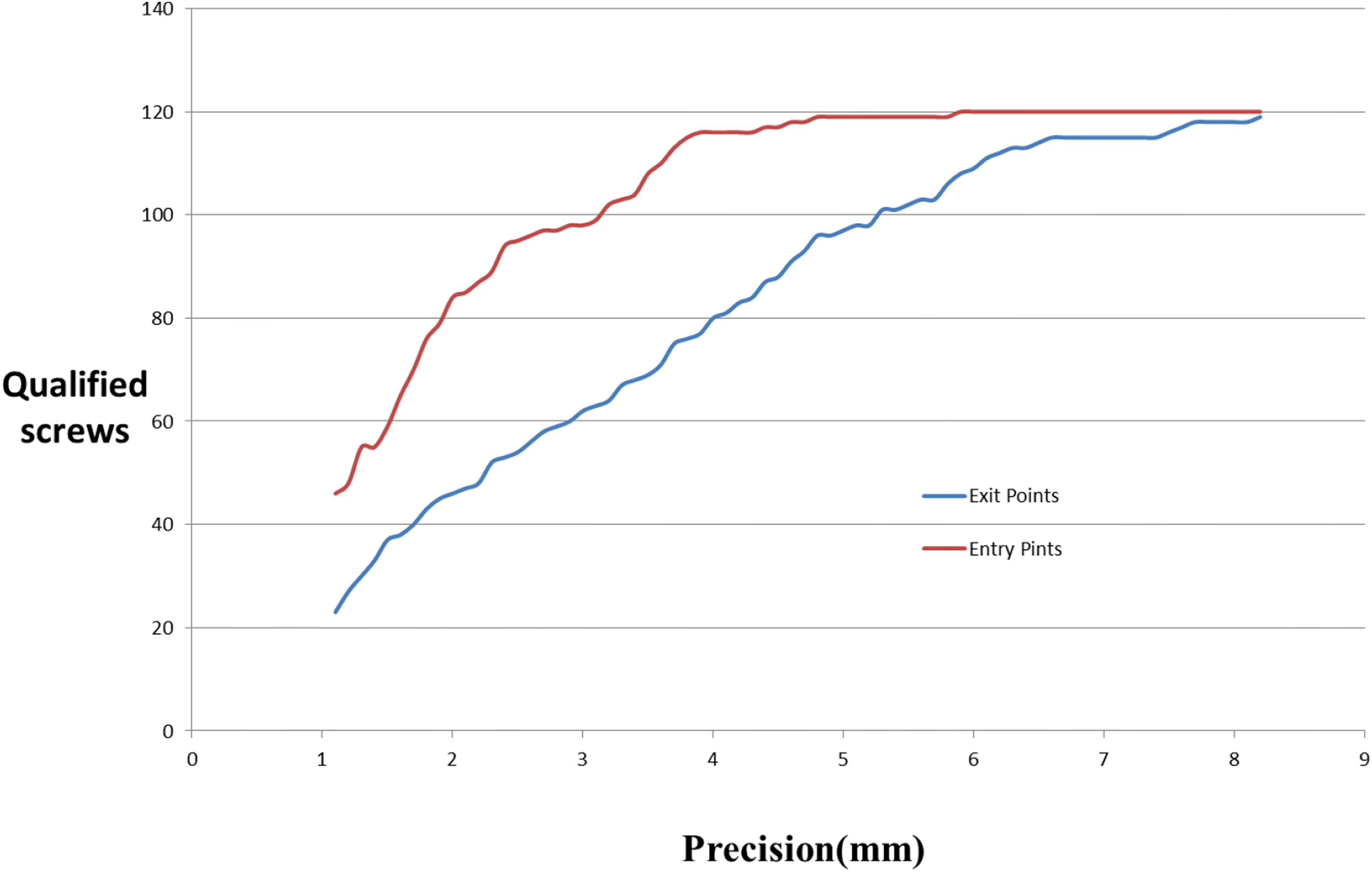
Qualified screws with different precision levels for both entry and exit points.
Evaluation of accuracy of screw entry and exit points
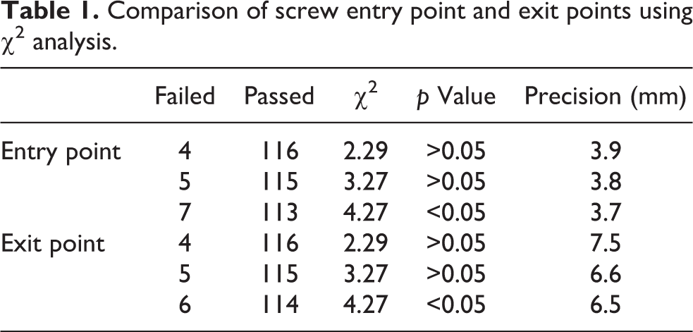
As presented in Table 1, when the accuracy requirement for the entry point was 3.8 mm, there was no statistically significant difference between the two groups (p > 0.05), that is, the accuracy of the entry point could only reach 3.8 mm. Similarly, the screw point accuracy could only reach 6.6 mm.
Comparison of screw entry point and exit points using χ 2 analysis.
Discussion
Contradictions between requirements for less trauma and better reduction and internal fixation always exist in the surgical treatment of calcaneal fractures. More specifically, achieving fewer incision-related complications requires minimal incisions 2 ; intra-articular fracture requires anatomical reduction 13 ; the fragility of calcaneus requires strong internal fixation, such as that achieved with the use of a larger locking plate; and the irregular morphological characteristics of the calcaneus and complex fracture conditions require more accurate internal fixation. The application of digital orthopedic simulation surgery offers the possibility to resolve these contradictions. In the present study, we divided the screw channel of a standard locking plate into a key screw channel and subsidiary screw channel. The key screw channel was the screw channel of the sustentaculum tali. The “utmost” internal fixation effect could be easily achieved in the software. Other than the two premises described earlier, the next problem to be solved is how to apply digital design in actual surgery.
The high standards for internal fixation of calcaneal fractures include minimal invasiveness, accuracy, and stability. These can be achieved through the following points according to our experience. In the present study, we applied the sinus tarsi approach for calcaneal fracture fixation. The approach involves entry about 1 cm below the lateral malleolus to the base of the fourth metatarsal and direct exposure of the anterior and posterior subtalar joints and calcaneocuboid joint. 6,14 Compared with the lateral L-type approach, the sinus tarsi approach has the following advantages: (1) it causes less trauma due to its short incision 15 and no damage to the lateral branches of calcaneal vessels, 15 calcaneofibular ligament, and retinaculum musculorm peroneorum inferus; (2) it provides better exposure of the subtalar articular surface and anterior calcaneus 16 ; (3) it causes fewer postoperative incision-related complications, resulting in overall superiority to the lateral L-type approach 5,17,18 ; and (4) it requires a shorter operative time and leads to less bleeding. 19 The disadvantages of this approach include (1) difficulty in reduction due to insufficiency of exposed operative field and failure to effectively reveal the posterior lateral surface of the calcaneus results in difficulty in the restoration of the calcaneus height, width, and heel tubercle, 20 possibly even inducing iatrogenic varus deformity 17 ; (2) stable fixation cannot be achieved for severe complex calcaneal fractures 21 ; and (3) frequently the specialized sinus tarsal bone plates 8 cannot achieve a stable triangular structure and satisfying overall internal fixation in severely complicated fractures. The sinus tarsi approach is very suitable for Sanders II and III calcaneal fractures 6 but not for severe Sanders type III fractures. 16,22 Thus, it does not completely replace the traditional lateral L-shaped approach.
Precise internal fixation is important for anatomical reduction. A sustentaculum tali screw is a screw that penetrates from the lateral wall of the calcaneus to the sustentaculum tali in the internal fixation of calcaneal fractures. The length of the screw path involves the posterior and middle subtalar joints or the anterior and middle subtalar joints. However, the shape of the sustentaculum tali is flat, and the talar head between the posterior and the anterior subtalar joints does not protrude into the calcaneus, which makes it difficult to control the direction of the screw channel and to prevent protrusion to the subtalar joint. 23
Sustentaculum tali screws have important biomechanical significance. The attachment of the triangular ligament and the pedicled ligament on the sustentaculum tali locks it in place during calcaneal fracture fixation. 24 Also, the placement of a longer screw in the sustentaculum tali and the characteristics of this hard mass promote the stability of the internal fixation.
Quantification of the differences between the RS and DD groups based on offset values of the screw coordinates
Zhang et al. 10 –12 used the absolute values of the differences between the preoperative and postoperative coordinates for screw entry and exit points to evaluate the differences in accuracy between actual surgery and digital design. However, this method is tedious in data processing, because different specimen experiments have different coordinate systems, and it is difficult to conduct a unified analysis. Our method simplifies and improves the methods of Zhang et al. In the present study, the spatial distance of the corresponding screw point, that is, the offset value, was directly used as a quantitative index to judge the difference between the RS and DD groups. Although our method and Zhang’s method are essentially the same, they both reflect the degree of deviation in the screw points in space. However, our method is more simplified, intuitive, and easy to understand. Our results showed that the screw entry and exit point offsets were 1.71 ± 0.11 mm and 3.10 ± 0.19 mm, respectively.
To determine whether RS is equivalent to DD, the concepts of “accuracy level” and “qualified screw” need to be introduced. For the RS group, the number of qualified screw was artificially extracted (n/120) for every 0.1 mm of offset value and compared with the number of qualified screws in the DD group (120/120) using the χ 2 test. A value of p > 0.05 indicated that there was no significant difference between the RS and DD groups in terms of accuracy. Also, the corresponding precision level can be regarded as the experimental precision level.
The experimental precision level is also a critical value. In the present study, the experimental precision values of the entry and exit points were 3.8 and 6.6 mm, respectively. This means that when greater precision is required, namely a precision level at the entry point ≤3.7 mm and a precision level at the exit point ≤6.5 mm (p < 0.05), RS cannot be considered the same as DD.
Achieving precise total internal fixation of calcaneal fractures through placement of the key screw channel under guidance
On the one hand, the anatomical features of the tarsal sinus and sustentaculum tali are advantageous for navigation module design. The tarsal sinus is a conical cavity located between the anterior part of the calcaneus and the talus neck. The main factors related to the design of the navigation module are (1) the position of the occipital sinus includes part of the calcaneus anterior subtalar articular surface, the lateral wall of the calcaneus and the fibular trochlea, and so on, which have irregular morphological features with good bone quality that is beneficial for sinus tarsi module placement; (2) the tarsal sinus cavity can accommodate a certain thickness of the card module; and (3) the main structure within the tarsal sinus is the fat pad, bursa and partial extensor digitorum brevis muscle, which does not affect the exact card position.
The superior surface of the sustentaculum tali is concave and articulates with the middle calcaneal surface of the talus, and the subtalar articular surface supports the talus neck. The characteristics of the sustentaculum tali are that the bones are rigid, have a stable position, and are less prone to fractures. 25 The sustentaculum tali screw is actually a screw that penetrates the lateral wall of the calcaneus to the sustentaculum tali and plays an important role in the internal fixation of the calcaneus. It is a “key screw.” In the present study, the sustentaculum tali screw was placed on the lateral wall of the anterior part of the calcaneus and under the anterior subtalar articular to the sustentaculum tali to support the anterior and middle subtalar joints.
On the other hand, it is important to achieve good overall internal fixation through precise placement of key screw tunnel. The sustentaculum tali screws can cause the steel plate and the sustentaculum tali to form an integral body, so that the posterior articular surface can be reliably fixed. If the sustentaculum tali screw does not penetrate through the steel plate, when the posterior articular surface is subjected to force, it will easily tilt and drift. This problem has been confirmed by a previous study. 26
The advantages of virtual internal fixation using a standard anatomical locking bone plate of the calcaneus are the following: (1) in the case of calcaneus fracture, a locking plate has better biomechanical properties than a nonlocking plate, especially in the case of osteoporosis; 27 (2) the navigation module can be used to achieve the accurate layout of the key screw (sustentaculum tali screw), that is, to determine the entry points and the direction of the key screw tunnel; and (3) good overall internal fixation can be achieved through the key screw tunnel. After the key screw tunnel is identified, the position of the bone plate and the direction of the other screw tunnels are also determined; and (4) the distance between the bone plate and the bone surface is adjusted to ensure smooth placement of the bone plate.
The connecting rod converted from the free curve could simultaneously navigate multiple screw tunnels. De Boer et al. 28 used a two-way navigation device from the lateral wall of the calcaneus to the sustentaculum tali. During the experiment, the placement of screws was determined by palpation. The results showed that the there was no difference in accuracy achieved using the guide versus palpation. This method could only guide the sustentaculum tali screw and cannot achieve good overall internal fixation.
The free-form curve can only be viewed in Mimics and can only be edited as a connecting rod after the SolidWorks conversion. Our results showed that the connecting rod can be used to connect the screw support columns at different positions above the cortical bone surface. Therefore, it can not only guide the key screw tunnel but also guide the minor subsidiary screw tunnel and ensure the correctness of the position of the bone plate and the direction of the screw.
A few notes from our successful experiences are provided below. The field of view (FOV) of a thin-bed CT scan can significantly affect the results of 3-D reconstruction and the high-precision printing of large objects using 3-D printer. It is important to ensure that the lateral wall of the calcaneus is sufficiently separated and the bone plate can be accurately placed without resistance during surgery. It is also important to ensure that the soft tissue is cleared at the module placement position to facilitate the placement of module into the position and the successful placement of the screw. In addition, we have conducted a clinical study in patients with Sanders II–III calcaneal fractures and observed satisfactory results; long-term follow-up is still ongoing.
Footnotes
Declaration of conflicting interests
The author(s) declared no potential conflicts of interest with respect to the research, authorship, and/or publication of this article.
Funding
The author(s) disclosed receipt of the following financial support for the research, authorship, and/or publication of this article: This research has received financial support form the Non-US government projects which are listed below with their project numbers: South Wisdom Valley Innovative Research Team Program (NO. 2015CXTD05); National Key R&D Program of China (NO. 2017YFC1103403); Sanming Project of Medicine in Shenzhen (No. SZSM201612019); The Science and Technology Project of Guangdong Province (No. 2016B090917001), No. 2016B090913004, No. 2016B090925001, No.2017B090912006)