
Abstract
Purpose:
Following the radial head replacement, the surface mismatches between the implants and the morphological characteristics of the original proximal radius decreased contact areas and increased contact forces which is potential for the long-term articulating cartilage wear. Several studies demonstrated that the individualized prosthesis, created from computed tomographic (CT) images of the contralateral side with the reverse engineering technology, may reduce the mismatch. The aim of this study is to demonstrate the matching precision of the reverse contralateral head between the surface registration in tuberosity-neck (TN) area and in tuberosity-diaphysis (TD) area.
Materials and Methods:
High-resolution CT scan of 11 pairs of the cadaveric arms was performed. Utilizing advanced image processing techniques, three
Results:
No statistically significant difference was found in all parameters from both TN and TD registrations (p < 0.05).
Conclusion:
The surface registration in either TN or TD area can generate the statistically symmetrical 3-D model with the original head. The registration in these areas may possibly be used in creating the individualized radial head prosthesis.
Introduction
The radial head replacement has been accepted as the standard treatment method for irreparable radial head fractures associated with elbow instability. 1,2 Precisely replicates individual anatomy is incapable to achieve by any currently available prosthetic designs. 2 –4 The surface mismatches between the radial head implants and the morphological characteristics of the proximal radius decreased radiocapitellar contact areas and increased radiocapitellar contact forces which is potential for the long-term cartilage wear. 5 –9
Based on the symmetry of the human skeleton, we can use the reverse engineering technology to manufacture the anatomical prosthesis for the missing part of individual patient by converting the 3-D images of the normal bone to the contralateral side. 10,11 The recent morphological study indicated that the radial head implant derived from the reverse engineering technology can reduce the mismatches. 12 However, the surface registration in creating the model was performed in the radial head area which may be not practical in use for the radial head fractures. Due to the variable fracture configurations with the different extents of radial head and neck involvement, the registration in the remaining intact areas of the proximal radius may be required. The accuracy in generating the prosthesis in the different areas of registration in the proximal radius is unknown.
The objective of this study was to demonstrate the matching precision of the reverse contralateral head in two areas of surface registration: the tuberosity-neck (TN) and tuberosity-diaphysis (TD).
Materials and methods
Eleven pairs of the embalmed cadaveric arms were used for the study (6 males, 5 females) with the mean age of 76.9 years (range 59–87). The screening X-rays of all specimens were used to exclude the preexisting bony deformity. Specimens were denuded of soft tissues.
The overall experimental process is shown in Figure 1. A high-resolution computed tomographic (CT) scan was made for each specimen (Philips Brilliance 64 CT scanner, Cleveland, Ohio, USA; voxel size 0.2 × 0.2 × 0.3 mm3, 120 kV, 150 mAs, pitch 0.5) and reconstructed into 3-D images. The 3-D rendered model of the left side was reversed to match with the right side in the same cadaver. The surface registration in the TN area and TD area was performed. The TN area started from the head–neck junction to the distal edge of radial tuberosity. The TD area started from the proximal edge of radial tuberosity until 2 cm of proximal diaphysis below the distal edge of radial tuberosity. The coronal, sagittal, and axial planes of the right-sided model were determined to be used as references. The coronal plane was formed on the center of the radial head and the line through the widest bone at the midpoint of sigmoid notch. The sagittal and axial planes were formed perpendicular to the coronal plane. The automatic measurement in each plane was performed in the cut showing the largest area of the radial head using the Matrix laboratory software (MATLAB 2017b, The MathWorks, Natick, MA, USA).

The overall experimental process. (a) 3-D models of each specimen was generated. (b) The model of the left side was reversed to match with the right side in the same cadaver. (c) The surface registration in the TN area and TD area was executed. (d) The automatic measurement was performed using the Matrix laboratory software (MATLAB).
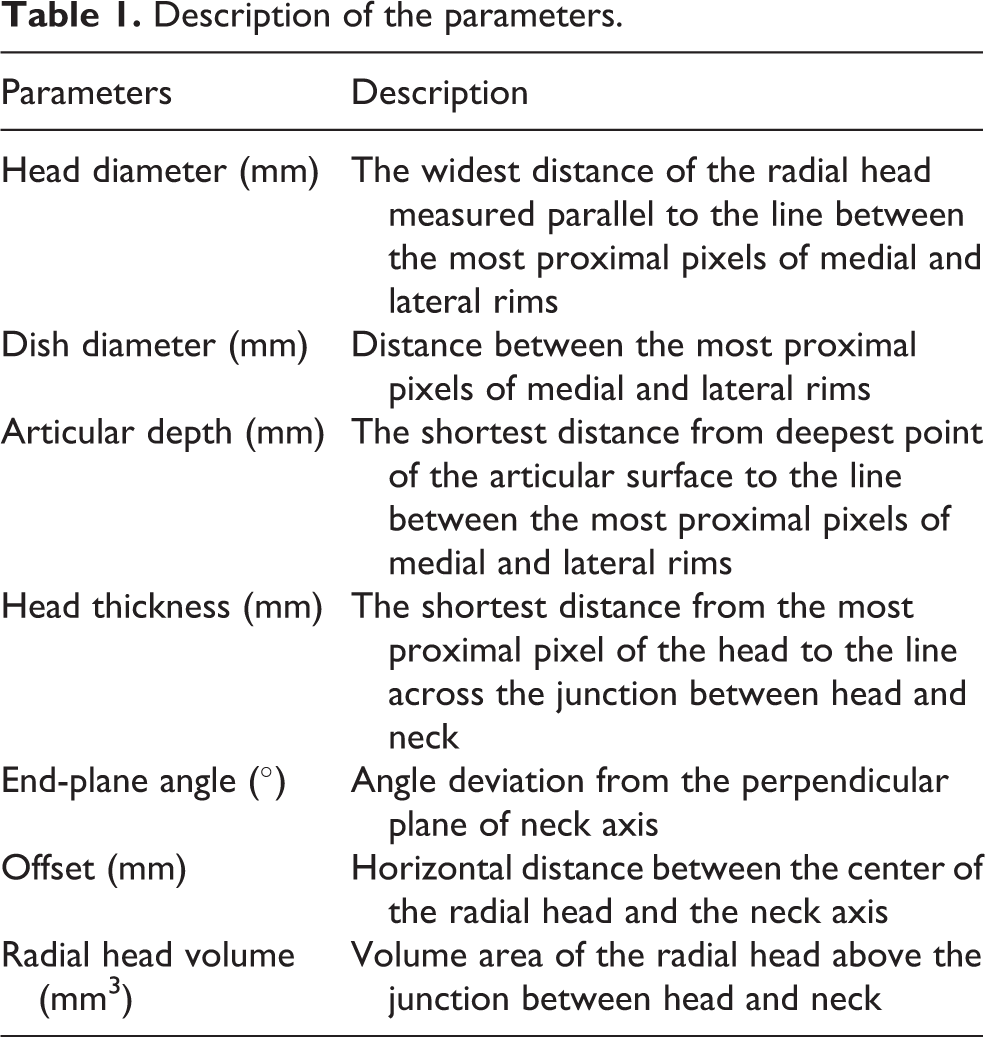
A description of each measuring parameter is given in Table 1. The line created from the most proximal pixels of lateral and medial rims had been used for the reference to measure the head diameter, dish diameter, articular depth, and head thickness. The neck axis was determined by drawing the line across the midpoints between the medial and lateral outer cortexes at the head neck junction and at 10 mm below the head neck junction. The neck axis had been used to measure the end-plane angle and offset (Figure 2). The alteration of all parameters from TN and TD registrations were measured and analyzed by paired t-test.
Description of the parameters.

Pictures shown a coronal view of one cadaveric arm. The cut showing the largest area of the radial head was used for the measurement. (a) The line created from the most proximal pixels of lateral and medial rims had been used for the reference to measure the dish diameter (DD), head diameter (HD), articular depth (AD) and head thickness (HT). (b) The neck axis had been used to measure the end plane angle (EPA) and offset (OS).
Results
The mean and standard deviation of the parameters of each model in the coronal and sagittal planes are given in Table 2. All evaluation parameters were normally distributed.
Mean and SD of all parameters in each model.

TN: tuberosity-neck; TD: tuberosity-diaphysis; SD: standard deviation.
The mean and standard deviation of the difference of all parameters in each model, the absolute maximal different value, and p value are presented in Table 3. No statistically significant difference was found in all parameters from both TN and TD registrations (p < 0.05).
Difference of original-TN registration and original-TD registration.

TN: tuberosity neck; TD: tuberosity diaphysis; SD: standard deviation.
Discussion
In this study, the matching precision from two different areas of surface registration in generating the individual prosthesis was presented. The surface registration in either TN or TD area can generate the statistically symmetrical 3-D model with the original head.
The biomechanical assessment in the alteration of radial head diameter with the radial head replacement was recently reported. 13 The significant increasing interosseous membrane tension during dynamic forearm rotation was observed in the radial head prosthesis with 2 mm larger than the anatomical diameter. 13 The authors proposed that this may increase the proximal radioulnar joint forces with a potential for stem loosening or the development of cartilage erosions within the lesser sigmoid notch. The radiocapitellar contact area or and the contact force were not impacted if the radial head was increased or decreased in diameter by 2 mm. The maximal changes of diameter from TN and TD registration were within such range.
The concept of insertion of a radial head implant that is too thick has been termed “Overstuffing.” 14,15 Overstuffing causing malalignment of the radiocapitellar joint and lateral gapping of the ulnohumeral joint can create increased pressures or altered kinematics that can ultimately result in hyaline cartilage erosion, synovitis, and osteoarthritis. 16 Van Glabbeek et al. demonstrated that with 2.5-mm lengthening, the axial contact force increased significantly. 17 The subsequent biomechanical studies confirmed the similar finding and revealed the increasing trend toward higher pressures when comparing the native elbow and the increased thickness of the radial head. 18,19 However, the insignificant increases in the radiocapitellar joint contact pressures was observed with the 2 mm overlengthening. In the present study, the maximal values of the increased thickness from TN and TD registrations in both planes of measurement were less than 0.8 mm and 0.6 mm, respectively.
There is limited information regarding the effect of the end-plane angle alteration. Although the maximum threshold of articular angulation is still unknown, angulation of more than 20° commonly interferes with forearm rotation and is considered unacceptable. 20 The alteration of the end-plane angle following the replacement with axisymmetric radial head implant was previously described. 21 The mean alteration was 3.62° (range 0.3–8.9°) in the coronal plane and was 5.85° in the sagittal plane (range 0.3–14.2°). The maximal value of the alteration from TN and TD registration was less than the mean alteration reported in axisymmetric design.
From previous works on the morphological study of the proximal radius, the articulating dish depth of the native radial heads is variable. 6,11,12 In contrast, the dish depth in all commercial prostheses are constant. The current design are available from 1.0 mm to 2.6 mm. According to the study of Bachman et al., the mismatch of dish depth between the native radial head and prosthesis had a significant effect on the distribution and magnitude of radiocapitellar joint contact area. 6 The inconsistent dish depth was also revealed in the present study. The depth in coronal plane range from 0.87 to 1.82 mm and in sagittal plane range 0.87 to 1.90 mm. The TN registration created the alteration of dish depth 0.20 mm in the coronal plane and 0.20 mm in the sagittal plane in average, whereas TD registration created the alteration of dish depth less than 0.12 mm in the coronal plane and 0.17 mm in the sagittal plane.
Based on the current literature, to the best of our knowledge, there was no biomechanical study about the impact of changes of the other parameters including dish diameter, offset, and radial head volume following the radial head replacement.
The major limitation of this study is that the models generated through CT images showed only the subchondral bone. For this reason, the cartilage thickness was not accounted in the study. Giannicola et al. found that the cartilage thickness at the radial head circumference ranged widely from 0 to 3.5 mm. 22 As the thickness values within the articular dish were similar but increased toward the rim, it may contribute to dish depth and the radius of curvature. 23 The study in models that including cartilage thickness should be further investigated.
In conclusion, although the measurement demonstrated the difference in several parameters, the statistically insignificance with a small quantity in overall was revealed. Both TN and TD registration may possibly be used as the standard template in generating the individualized radial head prosthesis. The biomechanical tests regarding the elbow kinematic and joint contact pressure following replacement of the implant developed from such registration techniques should be further studied.
Footnotes
Declaration of conflicting interests
The author(s) declared no potential conflicts of interest with respect to the research, authorship, and/or publication of this article.
Funding
The author(s) received no financial support for the research, authorship, and/or publication of this article.