
Abstract
Purpose:
Clinical and biomechanical studies have reported that using supportive screws and a wire instead of the common Kirschner wires for modified tension band wiring improves the stability of fractured patellae. However, the effect of screw proximity on the fixation of a fractured patella remains unclear. Therefore a numerical study was conducted to examine the effects of screw proximity on biomechanical responses in a simulated patellar fracture fixed using two parallel cannulated screws and anterior tension band wiring.
Methods:
A patellar model with a transverse fracture and loads simulating patellar tendon forces applied on the patella were used in the present simulation. The surgical fixation consisted of two 4.0-mm parallel partially threaded cannulated screws with a figure-of-eight tension band made using a 1.25-mm stainless steel wire. Biomechanical responses at two screw proximities, 5 and 10 mm from the leading edge of the patella, were investigated.
Results:
Superficial screw placement (5 mm) yielded higher stability, lower wire loads, and lower bone contact pressures than the deep placement (10 mm). The deep placement of screws exerted a higher load on the wire but a lower force on the screw than superficial placement did.
Conclusion:
This is the first numerical study to examine the effects of screw location on the fixation of a fractured patella using cannulated screws and tension band wiring. Considering the favorable biomechanical responses, superficial placement (5 mm below the leading edge of the patella) is recommended for screw insertion when treating a transverse fractured patella.
Introduction
Patellar fractures account for 1% of bone traumas in adults. 1,2 Displaced fractures often require surgical fixation to restore the continuity of the extensor mechanism and congruent patellar articulation, particularly in young or high-performing patients. 1,3,4 Various methods for treating patellar fractures are available; however, the use of modified tension band constructs that convert tension forces at the patellar front into compression at the articular surface to promote healing remains the standard treatment. 5,6 Favorable outcomes have been obtained in clinical practice. 7 –11 Although two smooth longitudinal Kirschner wires (K-wires) have been used as supplements in the modified tension band techniques, clinical and biomechanical studies have reported that the use of cannulated screws as alternative supplements reduces skin irritation and implant loosening as well as provides improved stability. 12 –20 In contrast to the placement of K-wires 5 mm below the anterior patellar surface in the modified tension band technique (AO Surgery Reference 2008. Available from: http://www.aosurgery.org), the optimal placement of cannulated screws within the patella has been rarely reported and is incompletely studied. 14 In a cadaveric biomechanical study, Domby et al. reported that the proximity of screw placement to the articular surface had a nonsignificant effect on resistance to fracture opening. 14 However, variables such as stress on the wire, distribution of deforming forces, bone characteristics, and wire–bone contact pressure must be considered for ensuring the stability of the construct until fracture union and for preventing implant failure or loss of fixation. 15,19,21,22 Currently, measuring these variables or embedding minute sensors without disruption of the bone and wire in laboratory settings is difficult.
The finite element (FE) method, a numerical simulation that does not require sensors, enables researchers to measure internal stress, strain, and loading while controlling the sample variability. 23 –26 Therefore, this study examined the effects of screw proximity on the stability of a fixed patellar fracture using the FE method. Based on the fundamental concepts of the modified tension band technique used for treating transverse patellar fractures, biomechanical responses with screw placements at different depths, 5 and 10 mm away from the leading edge of the patella, were compared. 13 Furthermore, normal and osteopenic bones were considered in the simulation.
Material and methods
A FE method model consisting of a fractured patella fixed with two cannulated screws and anterior figure-of-eight wiring was created to investigate the effect of screw position on patellar biomechanical responses including gap opening, bone contact pressure, and wire tension forces. Two screw placements, 5 and 10 mm away from the leading edge of the patella, and two bone qualities, namely, normal and osteopenic, were considered in the simulation.
Solid modeling
An intact solid patella model was created based on the computed tomography images provided by the Visible Human Project of the National Institutes of Health (Bethesda, Maryland, USA), and all the procedures were performed in accordance with relevant guidelines and regulations. The images were recorded at 1-mm intervals and the bone contours were retrieved according to the gray values using the Avizo Version 6 (VSG SAS, Bordeaux, France) software package. The patella model was smoothed to obtain a high mesh quality and was imported into the computer-aided design software SolidWorks 2012 (Dassault Systemes SolidWorks Corp., Waltham, Massachusetts, USA). On the basis of the image, a 1-mm sheet was sectioned from the tail edge of the patella as cartilage. An ideal transverse fracture, without a gap, at the middle of the patella was created according to the Arbeitsgemeinschaft für Osteosynthesefragen/Orthopaedic Trauma Association (AO/OTA) 34-C1 classification (Figure 1(c)). Then two partially threaded cannulated screws (outer diameter 4 mm; length 42 mm; 207.642, DePuy Synthes, Pennsylvania, USA) and an anterior wire were used to fix the fractured patella. The screws were inserted parallel to the long axis of the patella, from the apex to the base of the patella. In this study, two screw positions, 5 and 10 mm away from the leading edge of the patella (Figure 1(a) and (b)), were considered. The screws were placed in the central third of the patella (Figure 1(d)) on the front plane. Anterior wiring was applied in a figure-of-eight, and the outer diameter of the wire was set at 1.25 mm (Synthes Inc., West Chester, Pennsylvania, USA).

Model consisting of patella, wire, and screws: (a) 5-mm placement of screws; (b) 10-mm placement of screws; (c) fracture type; and (d) screw position.
FE modeling
The solid model was imported into the ANSYS Workbench V17 (Swanson Analysis, Houston, Pennsylvania, USA) to further improve the mesh and simulation quality. Quadratic tetrahedral elements (solid 187 in ANSYS) were used to mesh the screw, wire, bone, and cartilage. The mesh density was increased by reducing the global element length. In total, 416 705 nodes and 264 215 elements were used for simulation in the model with screw placement 5 mm away from the leading edge of the patella (5-mm model). An identical mesh setting was used in model with screw placement 10 mm away from the leading edge (10-mm model). The bone–bone (at the fracture site), screw–bone, screw–wire, and wire–bone contact behaviors were set as frictional surface-to-surface contact behaviors (contact 174 and target 170 in ANSYS). The bone–bone, bone–metal, and metal–metal coefficients of friction were set at 0.45, 0.3, and 0.2, respectively. 27 The contact behavior between wires at the leading edge of the patella, near the fracture site, was not considered.
Material properties and boundary conditions
In the simulation, two different bone qualities, normal and osteopenic, were considered, and their material properties were defined following previous studies. 28,29 Reported maximum and average values were used for normal and osteopenic bone quality, respectively. 28 In normal bone, the elastic moduli of the cortical and cancellous bones were set at 1000 and 207 MPa, respectively, whereas those of the osteopenic bones were set at 325 and 100 MPa, respectively. The Poisson’s ratio of bones was set at 0.3. 28 The elastic modulus and Poisson’s ratio of the cartilage were set at 50 MPa and 0.46, respectively. 30 The screws and wire were made of stainless steel; therefore, based on the material properties of stainless steel, their elastic modulus and Poisson’s ratio in the elastic phase were 210 GPa and 0.3, respectively. In addition, the yield stress and tangent modulus were 260 and 1450 MPa, respectively, in the plastic phase. To consider the permanent deformation of stainless steel in the plastic phase, a bilinear hardening plastic material model was adopted using the engineering database in ANSYS Workbench.
The proximal side (base) of the patella was fixed, and a tension force of 850 N was applied on the patellar apex at two loading angles (45° and 0° (parallel) to the long axis) to simulate different patellar loading conditions of knee flexion and extension during ambulation. 31 In this simplified model, the articulating part of the distal femur was not created. The inferior surface of patella was defined as a compression-only support in ANSYS to simulate the support from distal femur condyles (Figure 2). Compression-only support enables the surfaces to only bear compression and not tension forces.

Boundary condition of the model. Application of force at 45° (left) and 0° (right) to the long axis of the patella.
Validation
To confirm the reality of the present FE model, the results of the present FE model with two screws, no wire, and an osteopenic bone were compared with the experimental test results obtained by Dargel et al. 32 Under the same loading angle (45° to the long axis of patella) in this study, the linear stiffness and the loads for a patellar displacement of 2 mm were used for comparison with the present FE model. The linear stiffness values for the 5- and 10-mm screw placements in this study were 196 and 74 N/mm, respectively, which were comparable with those observed by Dargel (147 ± 50 N/mm; Figure 3). Compared with the load required for a 2-mm displacement in Dargel’s study (351 ± 120 N/mm), compatible loads with different screw placements were noted in the present FE model (Figure 3).

Experimental results of linear stiffness (left) and loading with 2-mm displacement (right) obtained by Dargel et al. 32 compared with the results of the FE model. FE: finite element.
Assessments
The total displacement of the fractured patellar fragment, maximum gap opening at the fracture site, maximum principle stress and tension force on the wire, and contact pressure on the anterior bone surface after static balance were used as indices for evaluating the effects of various screw placements. The displacement of the fractured patellar fragment and the maximum gap opening were used as indices of stability. The smaller the maximum displacement and gap opening, the higher the stability. Because a smooth wire was used and because of the presence of some irregular geometric features, such as turning points, only the maximum principle stress on the cross-sectional plane of the wire, near the fracture site, was examined. In addition, this part of the wire sustained the highest tension forces because it was on the edge of the tension side.
Result
The results indicated higher stability (smaller displacement and gap opening), lower wire loading, and lower contact pressure on the patellar surface when the screw was placed 5 mm away from the leading edge of the patella than when it was placed 10 mm away.
Total displacement and gap opening
Under different loading conditions, the fixed fractured patella exhibited higher stability during 0° loading of tension force than during 45° loading. Furthermore, the fractured patellar fragment and maximum gap opening at the fracture site were smaller when the screws were placed 5 mm away from the patellar surface than when they were placed 10 mm away (Figure 4 and Table 1). In the normal bone, the 10-mm screw placement increased the maximum displacement of the fractured patellar fragment (at the apex) by 1.5 times under 0° loading and by 1.3 times under 45° loading compared with the 5-mm placement. Similarly, the 10-mm placement increased the maximum gap opening at the fracture site by 1.56 times under 45° loading and by 1.58 times under 0° loading. The osteopenic bone exhibited higher maximum displacement of the fractured patellar fragment and a larger gap opening than the normal bone did under identical screw placements.
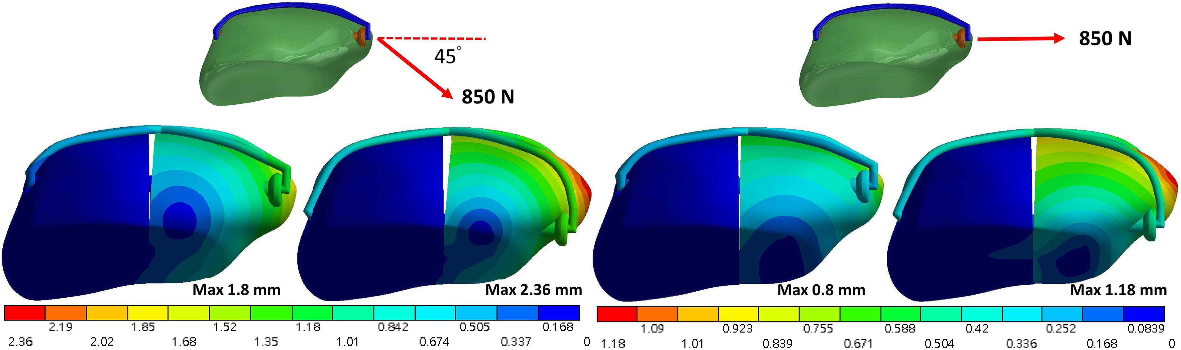
Total displacement of the normal-bone fractured patella under force at 45° (left) and 0° (right) to the long axis of the patella.
Maximum fracture gap opening and force distribution on the screws and wire.
Force and stress on the wire
After static balance, the load on the wire was higher, but the force on the screw was lower in the 10-mm placement than in the 5-mm placement (Table 1). The load on the wire in the 10-mm placement was 3.12 times (from 230 to 717 N) higher in the normal bone and 1.99 times higher (from 379 to 755 N) in the osteopenic bone than that in the 5-mm placement. Between the loading angles, the screws sustained higher loading when the tension force was applied at 0° than when it was applied at 45°. The maximum principle stress on the section plane of the wire at the midline near the fracture site increased more rapidly up to the yield stress of the stainless wire (260 MPa) in the 10-mm placement than in the 5-mm placement (Figure 5). The loads required to reach the yield stress of the stainless wire during 45° loading were 239 and 500 N, respectively, when the screws were placed 10 and 5 mm away from the leading edge of the patella.

Relationship between the maximum principle stress on the transverse section plane of the middle wire and force at 45° (left) and 0° (right) to the long axis of the patella.
Contact pressure on the bone surface
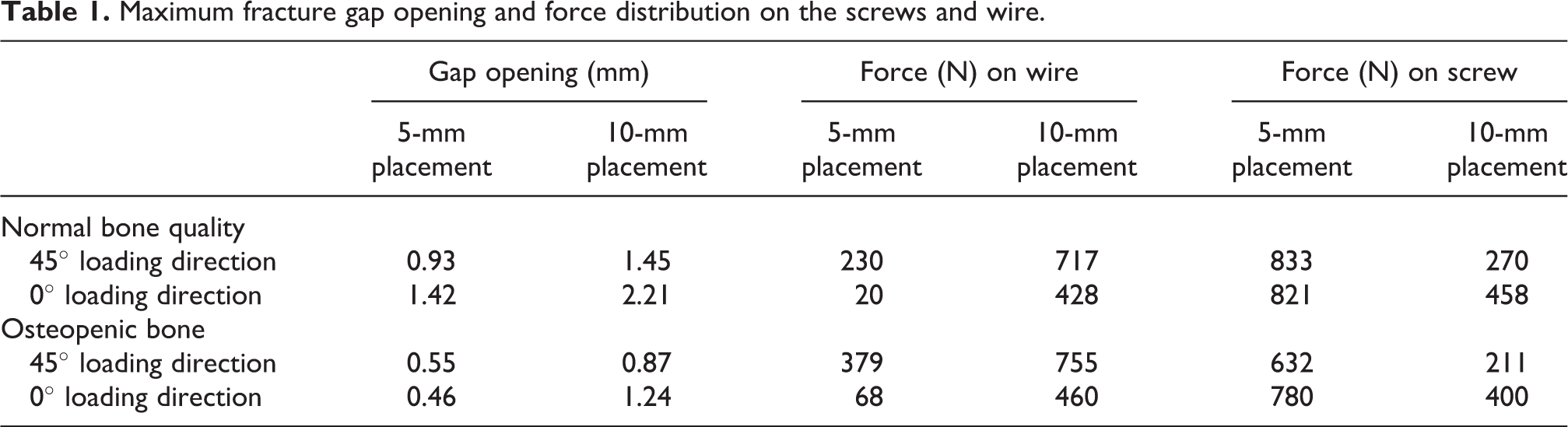
Under the wire, the contact pressure on the patellar bone surface was higher in the 10-mm screw placement than in the 5-mm screw placement (Figures 6 and 7). The peak bone contact pressures with the 10-mm placement were 7.7 times (99.5 to 764 MPa) and 2.5 times (344 to 858 MPa) higher than with the 5-mm placement in the normal and osteopenic bones, respectively. The contact pressure was lower during 0° loading than during 45° loading.
Contact pressure on the bone surfaces of normal (top) and osteopenic (bottom) bone with screws at distances of 5 mm (left) and 10 mm (right) under a force applied at 45° to the long axis of the patella.

Contact pressure on the bone surfaces of normal (top) and osteopenic (bottom) bone with screws at distances of 5 mm (left) and 10 mm (right) under a force applied at 0° to the long axis of the patella.
Discussion
This is the first FE modeling study to investigate the stability mechanisms in a fractured patella, fixed using tension band wiring and cannulated screws at different depths. Some biomechanical features, such as total deformation of the construct, opening of the fracture gap, force distribution in the wire and screws, wire stress, and contact pressure on the patellar surface, were studied. The results indicated that placing the cannulated screws closer to the leading edge of the patella provided higher stability than did placing them closer to the articular joint surface during the fixation of a transverse patellar fracture.
Fixation of patellar fractures with cannulated screws and tension band wiring is derived from the concepts of modified tension band techniques and is becoming increasingly prominent because it provides higher stability and causes less skin irritation than the conventional tension band wiring techniques. Theoretically, placing implants close to the tension side (anterior leading edge) of the patella can provide resistance to tension forces from the patellar tendon during knee flexion and extension. However, the optimal placement of the cannulated screws remains unknown. Domby et al. suggested that the effect of screw location on the stability of the fixed fracture was nonsignificant; however, the small sample size and variability among the samples might have adversely affected these results. In the present study, the economical FE method was adopted for clarifying biomechanical responses after a single intervention (location of screw placements) to eliminate the variability between samples.
A higher stability, smaller gap opening, and smaller displacement were observed when the screws were placed 5 mm away from the patellar articular surface than when placed 10 mm away; these finding suggest an effect of screw location on stability. A fractured patella can resist compression loading, but it is unable to resist tension loading. Consequently, the tension forces must be borne by the metallic screws and wire. Therefore, the closer the screws are to the tension side (anterior leading edge) of the patella, the higher the stability. The fractured patella is under tension forces from the patellar tendon and contact forces from the distal femur condyle, and it is continually bending. The center of rotation of the patella is near the trailing edge (articular surface). Therefore, the anterior leading edge of the patella is on the tension side, whereas the trailing edge is on the compression side.
Because the wires and screws share the load incident on the fractured patella, force distribution is a critical factor affecting the risk of wire breakage. When the cannulated screws were placed superficially with respect to the patella (i.e. 5 mm away from the leading edge), the force on the screws increased as the load on the wire decreased; this reduced the risk of wire breakage. Because screws have a larger cross-sectional area than do wires, allowing the screws to bear a larger proportion of the force than the wires is preferable for reducing the risk of wire breakage. This theoretical advantage of placement at 5 mm was demonstrated in the present study. In addition, the loads on the wire at 5- or 10-mm placements surpass the yielding stress of stainless wire; however, the capability of the entire model excluding the wire up to yield stress achieved with the 5-mm placement was higher than that achieved with the 10-mm placement (500 N vs. 239 N).
During 0° loading, with respect to the long axis of patella, the wire stress with 5-mm screw placement was considerably lower than that with the 10-mm placement, and the maximum values are less than the yield stress of stainless steel (Figure 5). In this loading condition, the screws bear a higher proportion of traction forces than of bending forces. In addition, when the screw is located close (5-mm placement) it induces higher loads on the screws than when the screws are located far (10-mm placement) from the loading site (patellar apex), and a higher traction effect than a bending effect is exerted by the applied force. By contrast, when the placement of the cannulated screws (10-mm placement) is deep, the bending effect increases because of an increase in the distance between the loading site (patellar apex) and screws. An increase in the bending effect increases the load on the wire relative to that on the tension side, and the stress reaches the yield stress of the stainless wire when the screw placement is deep. Higher wire loading increases the risk of wire breakage. If the surgeon has no alternative but to place the screws far away from the leading edge of the patella, the patella must be carefully protected from overloading.
High wire loading also leads to high contact pressures on the anterior patellar surface directly under the wire. The contact force between the bone surface and wire is associated with the wire tension. The contact pressure on the patellar surface increased with an increase in wire tension and after high contact force. High contact pressures on the patellar surface imply an increased risk of bone breakage; this finding is crucial for patients with osteopenic bones. In clinical practice, placing the screws near the anterior leading edge of the patella is preferable because of the force and stress of the wire, and the contact pressure on the anterior bone surface is lowered. Although the difference in the maximum gap opening between the 5- and 10-mm screw placements was not obvious (1.58 times), the difference in the wire forces was marked (3.12 times).
Similar to other FE studies, some inherent limitations in the present numerical simulation must be acknowledged. First, only simplified material properties and loading conditions were considered. Thus, the forces from patellar tendon and articulation with the distal femur condyles were considered in this simulation, while other constraints from the surrounding soft tissues, such as the patellar retinacula and connective tissues, were ignored. Moreover, a direct decrease in the elastic modulus of the normal bone was used to represent the osteopenic bone without considering morphological differences, hardening effects, and residual stresses of the steel wire in plastic phase during the bending or molding of a suitable tension band. In addition, static rather dynamic loads were applied. Second, only an ideal transverse patellar fracture type was considered in this simulation, and the results may not be applicable to other fracture types (i.e. longitudinal splitting or comminuted). Third, mechanical strength cannot be completely replaced using screws and a wire because of some inherent advantages of biological materials. The current study focused mainly on the fixation stability of the implanted devices rather than that of the bone. Clinical experience of patients with severe osteoporosis has suggested that the implanted metal devices may cut through the bone prior to bone breakage; in these cases, deep screw placement appears to be preferable to superficial placement to avoid the iatrogenic bony failure.
Conclusion
This is the first numerical study to examine the effects of screw location on a fixed fractured patella using cannulated screws and tension band wiring. Considering the favorable biomechanical responses in this study, the superficial placement (5 mm below the leading edge of the patella) is recommended for screw insertion for treating a transverse fractured patella.
Footnotes
Authors’ note
This article does not contain any studies with human participants or animals.
Acknowledgment
The authors acknowledge the United States National Library of Medicine and the Visible Human Project for the imaging data used to create the numerical model in this study.
Authors’ contribution
Yen-Nien Chen and Chih-Wei Chang contributed equally to this work.
Declaration of conflicting interests
The author(s) declared no potential conflicts of interest with respect to the research, authorship, and/or publication of this article.
Funding
The authors disclosed receipt of the following financial support for the research, authorship, and/or publication of this article: This work was supported by National Cheng Kung University Hospital (Taiwan) (NCKUH-10604024) and Show Chwan Memorial Hospital (Taiwan) (NCKUSCMH10612).