
Abstract
Introduction:
Tibial intramedullary nailing remains a common tibial fracture fixation method. Tibial nailing indications continue to expand. Neurovascular complications from tibial nailing have been described; however, the proximity of distal tibial locking bolts to the anterior tibial artery (ATA) variants has not.
Materials and Methods:
52 cadaveric legs were dissected identifying three common ATA variants. Each ATA variant received an intraluminal wire to facilitate fluoroscopic identification. Three different intramedullary tibial nails were inserted in each of the three ATA variant specimens. With fluoroscopy, the proximity of the distal locking holes of each tibial nail to the intraluminal wire representing the ATA variant course was measured.
Results:
Of the 40 measurements, the intraluminal wire was directly in the bolt insertional path in 8 of 40 (20%) and within 5 mm in 16 of 40 (40%). All specimens had the wire cross the locking bolt insertional path at least once in each of the nails. The ATA variant taking a more lateral course deep to the extensor digitorum longus and peroneus tertius to overlay the lateral malleolus had the highest occurrence of measurements less than 5 mm.
Conclusions:
The close proximity of tibial nail distal locking bolt holes to ATA variants presents a risk for iatrogenic vascular injury during insertion. The coronal locking bolts pose the greatest iatrogenic risk to the most laterally positioned ATA variant.
Introduction
The tibia is the most commonly fractured long bone, with tibial diaphyseal fractures accounting for 6.6% of all fractures. 1 –3 In the United States, an estimated 492,000 tibia fractures occur annually. 1,2 A recent survey demonstrated that the majority of orthopedic trauma surgeons prefer to manage tibial diaphyseal fractures with intramedullary nailing (IMN). 4 With the continued advancements in tibial nail implant design and operative technique, tibial IMN utilization continues to expand. 5,6
Although a common procedure, tibial IMN is not without risk, and the operative surgeon needs to be aware of the potential complications. 7 There is a reported 0.7–30% occurrence of neurovascular complications, along with numerous case reports of isolated vascular injury related to tibial IMN. 7 –12 When compared to other long bone IMN procedures, tibial IMN is associated with a higher risk of iatrogenic injury to the surrounding neurovascular structures. 13 The greater risk is related to the close proximity of neurovascular and tendinous structures to the location of the tibial nail locking bolts. 7,11,14,15 Since concomitant lower extremity vascular injuries often occur with tibial factures, additional iatrogenic vascular injury during IMN could further jeopardize limb viability.
Previous studies have described the risk of iatrogenic injury to the anterior tibial artery (ATA) during the placement of distal tibia locking bolts. 7 While the ATA commonly follows a predicable anatomic course at the ankle, the course can vary with an incidence of up to 12%. 16 –19 Three ATA course variants around the ankle have been described. First, in the presence of an absent or hypoplastic ATA, an enlarged perforating branch of the peroneal artery (PBPA) traverses the anterolateral tibia and assumes the dorsalis pedis artery course. 17 Second, on the anterolateral tibia, the ATA provides a lateral branch replacing the PBPA to supply the lateral aspect of the ankle. 17 Third, the ATA takes a lateral course crossing deep to the extensor digitorum longus and peroneus tertius to overlay the lateral malleolus before regaining its usual position in the foot. 17
The proximity of the ATA variants to tibial intramedullary nail distal locking holes has not been described. The objective of this study was to describe the proximity of the three most common ATA variants in relation to the distal locking holes of three commonly used tibial nails. The authors hypothesized that the ATA variants would be in close proximity to the distal tibial locking holes and would therefore present a potential risk for iatrogenic injury during locking bolt placement.
Materials and methods
After receiving appropriate institutional approval, 26 matched paired lower extremities were obtained from human embalmed cadavers ranging from 53- to 100-years old. No specimens had documented or observable leg, ankle, or foot pathology. The ATA was exposed and evaluated in all 52 specimens through a standard distal tibia anterolateral approach, which lead to the identification of three anatomical variants (specimens A, B, and C). In specimen A, an enlarged PBPA traversed the anterolateral tibia and assumed the dorsalis pedis artery course due to a hypoplastic ATA. In specimen B, on the anterolateral tibia, the ATA provided a lateral branch replacing the PBPA. In specimen C, the ATA took a lateral course crossing deep to the extensor digitorum longus and peroneus tertius to overlay the lateral malleolus before it regained its usual position in the foot.
Each specimen had a flexible, multifilamentous, stainless steel wire 1.6 mm in diameter inserted intraluminally throughout the entire course of its ATA. The anterolateral approach utilized for exposure allowed for direct visualization during wire insertion in order to ensure the wire did not displace the native course of the artery in the distal third of the leg. In the event resistance was encountered during the insertion process, a small vascular fenestration facilitated atraumatic wire passage. The wire’s location within the ATA was confirmed by exposing the popliteal artery in the popliteal fossa and dissecting it distally until the wire was identified within the ATA. Specimen B required the insertion of an additional wire within its lateral branch (Figure 1). Following the completion of wire placement, an anatomical soft tissue closure was performed on each specimen.
The lateral branch of the ATA. Specimen B had a lateral branch of the ATA, which required the placement of a second wire within the lumen of the arterial branch in addition to the wire in the ATA. ATA: anterior tibial artery.
Next, each specimen underwent axial transection 10 cm distal to the tibial tubercle. Meticulous technique was utilized to preserve the integrity of the vascular structures. A ball-tipped guide wire was then advanced distally down the tibial intramedullary canal, and fluoroscopic imaging (Fluoroscan, Northbrook, Illinois, USA) was used to confirm its final position at the level of the distal tibia physeal scar, centered on both the anteroposterior (AP) and lateral views.
Three 10-mm diameter tibial intramedullary nails from different manufacturers were selected for testing. Nail #1 (Smith & Nephew Trigen Meta-Nail, Memphis, Tennessee, USA) distally featured a 2° posterior bend, a sagittal bolt hole located 15 mm from the distal tip of the nail, and two coronal bolt holes located at 5 and 25 mm from the end. Nail #2 (Stryker T2 Nail, Kalamazoo, Michigan, USA) distally featured a 4° posterior bend, a sagittal bolt hole located 15 mm from the distal tip of the nail, and two coronal locking holes centered at 5 and 25 mm from the end. Nail #3 (Synthes Expert TN Nail, West Chester, Pennsylvania, USA) distally featured an oblique bolt hole 30° from the sagittal plane located 5 mm from the distal tip, a sagittal bolt hole located 22 mm from the distal tip of the nail, and two coronal locking holes centered at 13 and 37 mm from the end.
Next with the proximal alignment jig attached, the nails were inserted over the guide wire and manually advanced distally to the level of the distal tibia physeal scar. The nails’ final distal position was confirmed with fluoroscopy, and the alignment jig was aligned with the anterior tibial crest to ensure neutral rotation. Then, perfect concentric circles of each individual distal locking bolt hole were obtained with fluoroscopic imaging. These fluoroscopic views represented the common views utilized when inserting locking bolts via the “perfect circle” technique. 20 The fluoroscopic views obtained were digitally saved and hard copies were created for later analysis. This process was performed with all three nails in each specimen.
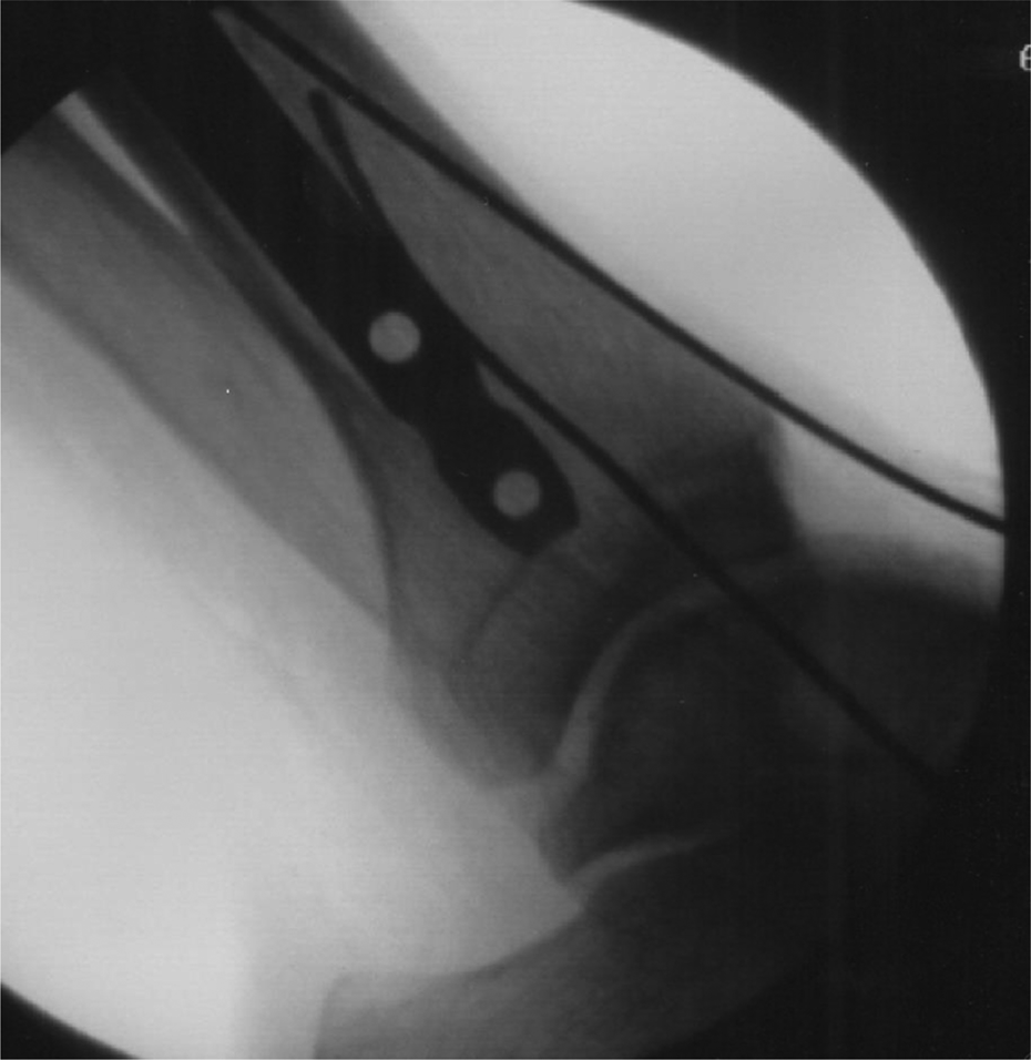
Utilizing the saved fluoroscopic images, the distances between the ATA intraluminal wire and the outer aspect of each distal locking bolt hole were measured through two steps. First, in PowerPoint 2003 (Microsoft, Redmond, Washington, USA), the distal bolt holes in each nail were fit with a circle tool that had crosshairs (Figure 2). The circle was enlarged and fit to the edges of each bolt hole, and the intersection of the crosshairs represented the center of the circle. Using the center of the circle of the bolt hole, another circle with crosshairs was enlarged until the edge of the circle touched the ATA, indicated by the intraluminal wire (Figure 2). Then, the radius of each circle was measured with a line tool that was calibrated based on the size of the known diameter of the given bolt hole. The radius of the circle to the ATA wire represented the minimum distance from the center of the hole to the artery. Finally, the distance between the ATA intraluminal wire and the outer edge of the locking bolt hole was recorded (mm) by subtracting the radius of the bolt hole circle from the radius of the circle to the ATA wire. When the wire was visualized directly within the bolt hole, a measurement of 0 mm was recorded, which meant the artery was in the direct insertional path of the locking bolt (Figure 3).

Measurement of distance of bolt holes from ATA. Bolt locking holes were fit with a circle tool with crosshairs. Using the center of the circle, as determined by the crosshairs, another circle with crosshairs was enlarged until the edge of the circle touched the artery as represented by the wire in the lumen of the artery. ATA: anterior tibial artery.

Intersection of ATA and a proximal bolt hole. Specimen A demonstrated a 30% occurrence of the ATA, as represented by the wire, being located directly in line with the insertional path of the locking bolt. ATA: anterior tibial artery.
Results
Insertion of the three nails in all three specimens yielded 40 measurements describing the proximity of each ATA variant to each distal locking hole (Tables 1 to 3). In 20% (8 of 40) of the total assessments, the wire was visualized directly within the bolt hole, and a measurement of 0 mm was recorded. In 40% (16 of 40) of the total assessments, the wire was measured to be less than 5 mm from the outer aspect of the distal locking bolt hole. The total number of measurements recorded as 0 mm and less than 5.0 mm was compared to assess the risk between anatomical specimens and risk between nails (Tables 4 and 5).
Results observed in specimen A.

Results observed in specimen B.

Results observed in specimen C.

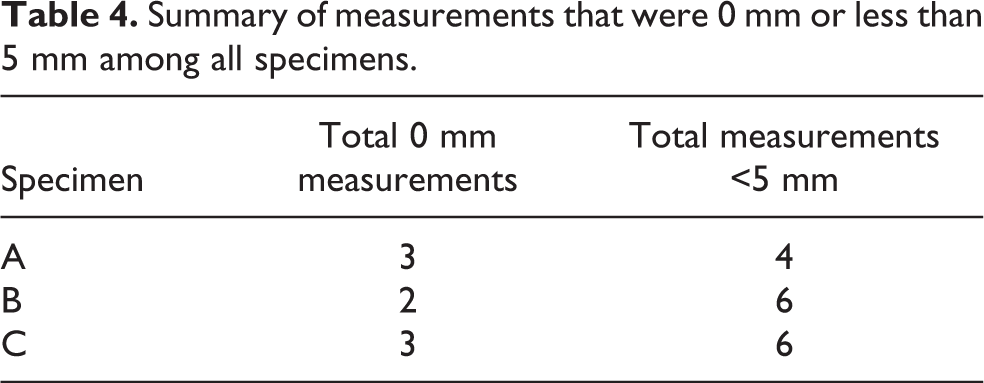
Summary of measurements that were 0 mm or less than 5 mm among all specimens.
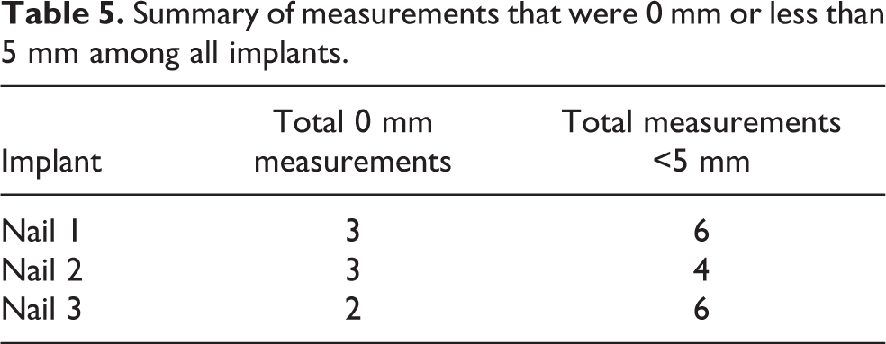
Summary of measurements that were 0 mm or less than 5 mm among all implants.
When comparing all of the measurements of each specimen regardless of the tibial nail used, both specimen C and specimen A demonstrated 3 of 10 occurrence of the wire being located over a locking hole (Figure 3), while specimen B only recorded 2 of 20 (10%) occurrence. Specimen C demonstrated the highest occurrence of the ATA being less than 5 mm from one of its locking holes at 6 of 10, compared to specimen A at 4 of 10 and specimen B at 6 of 20 (30%).
When comparing the measurements of each individual tibial nail across all specimens with regard to a wire intersecting a locking hole, the results demonstrated a similar occurrence rate between nails 1, 2, and 3 at 3 of 12, 3 of 12, and 2 of 16, respectively. Recorded measurements of less than 5 mm from a locking hole had the highest occurrence rate in nail 1 at 6 of 12, and slightly less in nails 2 and 3, at 4 of 12 and 6 of 16, respectively.
Each individual locking hole within the three nails was independently evaluated across all specimens. For all 0 mm measurements, the proximal coronal hole accounted for 5 of 8, the sagittal hole for 2 of 8, and the distal oblique hole for 1 of 8. The majority of measurements less than 5 mm were found in the proximal coronal hole with 8 of 16, and the rest were dispersed between the distal coronal hole with 4 of 16, sagittal hole with 3 of 16, and the distal oblique hole with 1 of 16.
The coronal plane locking holes were then collectively compared against the locking holes found in both the sagittal and oblique planes. Of the total measurements less than 5 mm, the proximal and distal coronal holes comprised 12 of 16 compared to the sagittal and oblique holes combining for 4 of 16. Six of 12 of the measurements less than 5 mm in the coronal plane were found in specimen C. All of the measurements less than 5 mm in the sagittal plane were found in specimen B.
Discussion
The current study has revealed that the placement of distal locking bolts during tibial IMN can iatrogenically injure ATA variants. All three specimens demonstrated the intraluminal wire fluoroscopically within a locking bolt hole, which verified the arterial variant being in the direct insertional path of a locking bolt. The data emphasize the importance of an awareness of ATA variants and their potential for iatrogenic injury during distal locking. Depending on the clinical situation, iatrogenic injury to the ATA could result in local complications, such as bleeding, hematoma, wound healing issues, or pseudoaneurysm formation. 8,10,14 In the presence of a high-energy limb injury associated with vascular embarrassment, additional iatrogenic injury to the ATA could result in a limb threatening situation. 11
IMN has long been the preferred operative treatment option for tibia diaphyseal fractures located more than 5 cm proximal to the tibiotalar joint. 2,21 Historically, tibial nailing of fractures located in the distal tibia was limited secondary to the inability to achieve adequate fixation in the distal segment. The inadequate fixation awarded by the older generation tibial nails was a product of their design, most specifically relating to the location and orientation of the distal locking bolts. 5,22 Commonly, these nails only allowed placement of two coronal distal locking bolts located 2–4 cm from the nail tip. This often created a suboptimal mechanical environment not conducive to fracture healing and correlated with high fixation failure rates. 23,24 In response to these problems, newer generation tibial nails were developed with design adaptations that improve construct stability. The new design adaptations included bolts located more distally within the nail, an increased number of distal locking bolts, and bolts orientated in multiple planes. 5,6,25,26 The advancement in nail design specifically relating to the distal locking holes has helped broaden the indications for tibial nailing, but has also introduced new potential operative complications.
The potential risk that the orientation of the distal locking holes contributes as they relate to the normal anatomic course of the ATA has been presented by previous authors. Roberts et al. examined the risk to the posterior and anterior tibial neurovascular structures during distal locking bolt placement in the coronal plane. They found that, regardless if the bolt was inserted from medial to lateral or lateral to medial, the anterior neurovascular structures were located 0.5–4.8 mm from the locking bolts and placed at substantial risk for injury. 13 Further, Bono et al. studied the iatrogenic risk placed on the anterior neurovascular bundle of the ankle during placement of the AP distal locking bolt. They discovered that in 13 of 16 of their specimens, the anterior neurovascular bundle laid directly over or adjacent to the bolt head, and an arterial injury was noted in 25% of those specimens. These findings lead the authors to strongly encourage the use of precise technique when performing tissue dissection, drilling, and bolt placement to help avoid possible complications.
In this study, the authors examined the proximity of the sagittal locking bolt in each nail to the three ATA variants. They found that regardless of the nail used, neither specimen A nor specimen C recorded their wire to be less than 5 mm from a sagittal locking hole. The more lateral course seen in these variants afforded them protection from injury when placing AP-orientated locking bolts. Locking holes in the sagittal plane were only responsible for 3 of 16 of all the measurements less than 5 mm, of those 3 of 3 are found in specimen B. In specimen B, the ATA variant is comprised of a medial branch and a lateral branch. Only the medial branch was recorded to be less than 5 mm from the sagittal hole. The medial branch follows a similar path as the normal ATA along the anterior tibia near the insertion site of instrumentation, which puts it at risk during incision, dissection, drilling, depth gage utilization, and screw insertion.
The proximity of the coronal locking holes in each nail to the ATA variants was evaluated and compared. All three ATA variants recorded measurements less than 5 mm from the coronal locking holes, but specimen C had the highest occurrence rate at 6 of 12 compared to specimens A and B both with 3 of 12 occurrence. In specimen C, the intraluminal wire was found to overlay each proximal coronal hole and to be less than 5 mm from each of the distal coronal locking holes in each of the tibial nails. The ATA variant in specimen C took the most lateral course of the three, crossing deep to EDL and peroneus tertius along the anterolateral tibia heading toward the lateral malleolus before redirecting more anteromedial to regain its normal position in the foot. Its position along the anterolateral tibia and the lack of a muscle belly between it and the tibial cortex makes this variant vulnerable to injury when placing a coronal locking bolt. Overall, the proximal coronal hole when compared to all of the locking holes has the highest occurrence rates of both the wire overlying the hole and being less than 5 mm from it at 5 of 12 and 8 of 12, respectively. The data indicate that there is a substantial risk when placing a coronal locking bolt, and this risk increases as the course of the ATA moves more laterally, or as the location of the coronal locking bolt moves more proximally. Precise technique should be used to avoid overpenetration of the drill bit, depth gage, or locking bolt when placing coronal locking bolts, especially in the proximal coronal hole in patients with lateral coursing vascular variants.
When comparing the intramedullary nails, all three recorded measurements less than 5 mm from their coronal locking holes to anterolateral vessels. However, the 4° posterior distal bend in nail 2 did demonstrate some advantage by slightly moving the distal coronal hole more posteriorly; this resulted in an increased distance between the hole and the wire. Also, nail 3 requires further attention secondary to its distal oblique hole oriented 30° from the sagittal plane. Although the data show that this oblique hole places some of the anterolateral vessels at direct iatrogenic risk, the additional distal locking hole did not result in an overall increase of total iatrogenic risk of injury.
A limitation of the present study involved the utilization of atraumatic specimens with an intact tibia. One must acknowledge that the presence of a tibia fracture may result in alteration of the native course of the ATA. Second, an additional limitation of this study involved the use of the perfect circle technique. While the perfect circle technique during distal locking bolt placement accurately mimics true intraoperative technique, the technique is subject to human interpretation and slight deviations could have affected the measurements. Next, the indirect measuring technique is another methodological shortcoming of this study. While a direct measuring technique between the ATA variant and the distal locking bolts would have been preferable, the indirect measuring technique preserved the structural integrity of both the artery and distal tibia. Such specimen preservation allowed comparison of specimens with different intramedullary nails. Finally, one must consider that the iatrogenic risk to the ATA could be underrepresented in the results, as the true diameter of the ATA is larger than the intraluminal wire diameter. In addition, the locking bolt heads are larger in diameter than the insertion hole, therefore further shortening the distance to the ATA.
Conclusion
This study concludes that the ATA variants are in close proximity to the distal tibial locking holes and are therefore at risk for iatrogenic injury during locking bolt placement. Of the estimated 358,194 fractures treated with tibial IMN in the United States, approximately 42,983 of them will have an ATA variation. 1 –4,16 –18 With a 0.7–30% reported rate of neurovascular complications associated with tibial IMN, this could equate to 300–12,894 complications in this projected ATA variation group of 42,983. 7 –10,12 These numbers can be expected to increase as recent innovations in both nail design and operative technique have broadened the indications for tibial nailing. Since tibia fractures are often associated with concomitant vascular injuries, the avoidance of further iatrogenic vascular injury is paramount. 22 Therefore, a thorough knowledge of the lower leg’s vascular anatomy and its proximity to the selected implant is critical for avoiding iatrogenic complications. This study emphasizes the relative risks that the ATA variants present when performing tibial IMN in hopes that this information will be considered during future procedures and potentially reduce preventable complications.
Footnotes
Acknowledgment
The authors would like to thank Dilraj Sekhon for data collection assistance.
Declaration of conflicting interests
The author(s) declared no potential conflicts of interest with respect to the research, authorship, and/or publication of this article.
Funding
The author(s) received no financial support for the research, authorship, and/or publication of this article.