
Abstract
Introduction:
The aim of this study was to evaluate the effect of different heights of attachment and mucosa thicknesses on the stress distribution of two implant-retained mandibular overdenture designs under loading using the photoelastic stress analysis method.
Materials and methods:
Six photoelastic models of an edentulous mandibula were fabricated with two solitary implants that were placed in the canine regions. The attachment systems studied were ball and locator stud attachments. Both the ball and locator groups included three models that had different residual ridge heights so as to provide different mucosa thicknesses (1 mm–1 mm, 1 mm–2 mm, 1 mm–4 mm). A static vertical force of 135 N was applied unilaterally (each on the right then the left side) to the central fossa of the first molars. Models were positioned in the field of a circular polariscope to observe the distribution of isochromatic fringes around the implants and the interimplant areas under loading. The photoelastic stress fringes were monitored and recorded photographically.
Results:
The ball attachment groups showed higher stress values than did the locator groups under loading. Both attachment systems produced the lowest stress values in stimulated 1 mm–1 mm mucosa thickness models. The models with 1 mm–2 mm mucosa thicknesses showed higher stress values than did other models for both attachment systems. The highest stress value observed around both attachment systems was the moderate level in all test models.
Conclusion:
In different height mucosa thicknesses, locator attachment models distributed the load to the other side of the implant and its surrounding tissue, whereas the ball attachment did not. Regardless of mucosal thickness and attachment type, the implant on the loading side was subjected to the highest stress concentration.
Introduction
Poor retention and instability of dentures are the chief reasons for functional problems and complaints in edentulous patients. Bone resorption is often remarkably greater in the mandible than in the maxilla in these patients. 1 Due to this natural process in the mandible, there is a need to increase retention and support of overdenture prostheses in conjunction with implant rehabilitation. 2 Since several studies reported3,4 high success rates for implant rehabilitation, overdentures have become an acceptable alternative for patients with severe residual ridge resorption. In addition to the increased retention and stability that an implant-supported overdenture (ISOD) allows, further advantages over conventional complete dentures include increased comfort and chewing abilities,1,5 protection of the residual ridge, and an enhanced quality of life. 6
According to the McGill Consensus Statement of 2002, the primary treatment option for edentulous patients is ISOD using two solitary implants in the mandible.2,3 Mandible overdentures planned with two implants satisfy the requirements for treatment and lead to low surgical damage of tissue; this method also costs less and is the simplest proper prosthodontic procedure. 7 The abutment types commonly used for the two implant-supported mandible overdentures include bars of different designs as well as balls and magnets.8-11 The recently presented locator system has been widely used by dentists and has gained a considerable market share in the implant industry. 8 It has been introduced as an alternative single attachment against the most used retention system, which is called the ball anchor system. Although both stud attachment systems have been used for several years in the implant industry, there remains a lack of detailed information about them. There are various opinions regarding the superiority of each, the various implant heights, and mucosa thickness on the stress distribution.12,13
The soft tissue structure and shape around the bone and the implant types used might affect the stress distribution in the cortical bone that is located in the peri-implant zone. Overloading situations may also cause wearing out of parts of the implant system or micro/macrofracture of the implant due to the incompatibility between components or failure of the implant due to crestal bone loss.8,14 Height of the attachment and mucosa thickness are also important factors in the design of ISODs. To reduce the lever arm effect that increases the level of stress transmitted to the peri-implant bone, the attachment must be as short as possible. The height of the attachment also influences space requirements inside the denture, and fractures may occur with insufficient acrylic resin thickness.15,16 Mandible bone resorption can occur at various levels in the right and left side of the anterior mandible. 17 This condition introduces the need to use an attachment with a different vertical height level, such that two independent implants can be positioned at the same occlusal height, parallel to the occlusal plane. If one implant was higher than the other, the prostheses would disengage from the lower implant during function and would rotate primarily on the higher implant. This situation accelerates the wear of the attachment on the lower implant, and because the higher implant receives the majority of the occlusal load, an increased amount of crestal bone loss can occur.18,19
Similarly to other bones, mandibular bone can be regarded as a composite material. 20 Polymers and fiber-reinforced polymers can be used to replicate the mandible spongy and cortical bones, respectively. 21 The mandible model used within this investigation is a photoelastic polymer based on an epoxy resin. 22 It has an elastic modulus of about 2 GPa, 23 thus the elastic properties of our model is in between the moduli of spongy and cortical bone. 24
A variety of techniques are used to simulate the mathematical and visual evaluation of the stress distribution of the implant and bone during chewing in the mouth. These are photoelastic stress analysis (PESA), two-dimensional (2D) or three-dimensional (3D) finite element analysis (FEA), and strain-gauge (SG) analysis. 25 Experimental SG analysis on mandible models is essential to calibrate theoretical FEA mandible models. 26 Among these methods, PESA eliminates the variations caused by the patient or the operator performing the experiment. This technique has been extensively used to investigate the interaction of tissue response and stress distribution among implant–bone prosthetic restorations and physical properties of implants in dentistry.27-29 Several studies have evaluated stress distribution between the same heights of attachments using FEA1,5 and SG; 30 the effects of implant angulation and prostheses connection have also been investigated, 31 but there is no study that evaluates different heights of attachments by using PESA. Therefore, the aim of this in vitro study was to evaluate the influence of different heights of attachments and mucosa thickness for two different ISODs, namely, the ball and locator attachment (Figure 1), on the vertical pressure and stresses around the implant surface bone under unilateral loading on overdenture prostheses using PESA method.
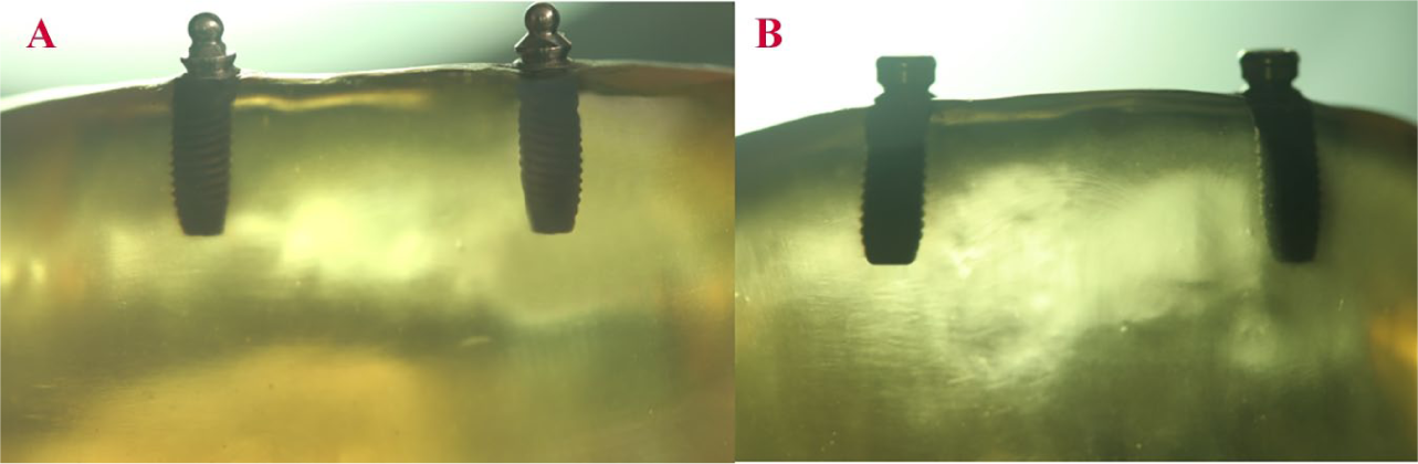
(A) Ball Attachment. (B) Locator Attachment.
Materials and methods
Preparation of acrylic and photoelastic models
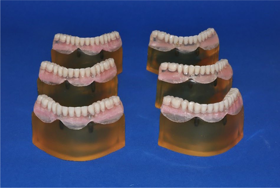
An edentulous mandible wax model (Poliwax, Bilkim Kimya, Izmir, Turkey) was fabricated and shaped in the same vertical height level for both sides of the mandible. A wax model was obtained from a patient who had adequate bone height of the mandible. This model was duplicated twice, and the midline of the second wax model was marked with a digital caliper. The left mandible area was diminished 1 mm below the right side (1 mm–2 mm). The third wax model was also shaped as the left side of the jaw was 3 mm lower than the right side (1 mm–4 mm). Then, three master wax models (1 mm–1 mm, 1 mm–2 mm, 1 mm–4 mm) were obtained and duplicated; the six models were obtained to produce two of each of the master models. These wax models were turned into six edentulous mandible acrylic models (Meliodent; Heraeus Kulzer, Hanau, Germany, Figure 2).
Acrylic models prepared according to different mucosa heights and then be converted to photoelastic models by placing ball and locator attachments (1 mm–1 mm; 1 mm–2 mm; 1 mm–4 mm).
The acrylic models were polished with 320-, 400-, or 600-grid silicon carbide abrasive paper. Two perforations were made in the canine areas with a parallelogram (Orthofex, Fogászat Gyártơ, KFT, Budapest, Hungary) and a distance of 22 mm between each of the two canine teeth was set in a similar manner to that in the mouth.27,32 Screw-type implants (Fixture OsseoSpeed™ Implant, Astra Tech, Mölndal, Sweden), 4.0×11 mm, were placed into holes in the acrylic models. Stud attachments, namely, the ball and locator, were merged with implants on the models. Using a drill at the top of the parallelogram, the height difference between implant levels was checked on both sides of the mandible to determine the reference point; ball attachment levels were checked from there at the peak point, while locators were controlled from their buccal points. Precise adjustments were made by checking the lines indicating the change in mm of the up-and-down movement on the side of the parallelogram to determine whether the vertical heights were the same. Thus, the implants were positioned evenly on top of the alveolar ridge. Six silicone impressions (Zetaplus, Zhermack, Rovigo, Italy) were derived from acrylic models that have implants and then photoelastic resin material (PL–2 and PLH–2; Vishay Measurements Group, North Carolina, USA) based on an epoxy resin was poured into the silicone molds according to the manufacturer’s recommendations.
Creation of mucosa morphology
As the prosthetic ending process on the model can create stress, the negatives of models were obtained with silicone impressions and stone models were prepared. Models were measured with a digital caliper from the center of the stone mold to the middle of the implants, and the same measured distance was marked on the distal side of the implants as a horizontal projection. These areas were defined as the limits for the determination of different mucosa heights while arranging the process of mucosa heights. Posterior edentulous areas of photoelastic models were fixed by light-polymerized base plates (Vertex U.V. Light Curing Trayplast, Vertex Dental, Zeist, Netherlands) at a 3 mm thickness to represent soft tissue thickness.33,34
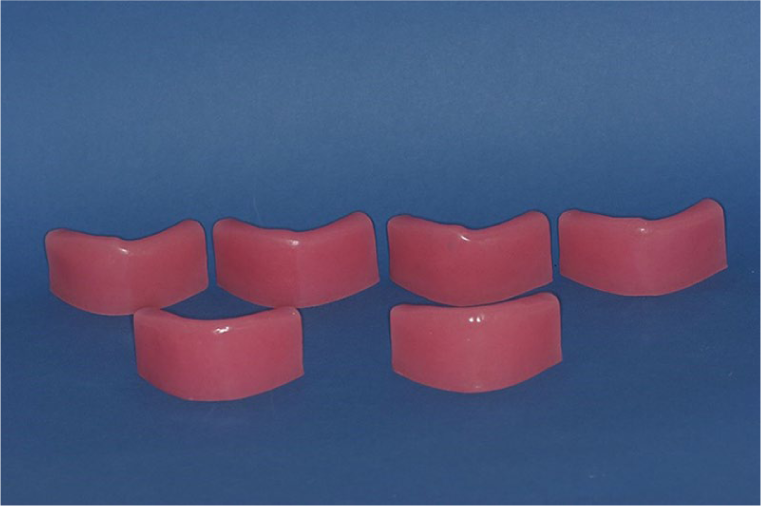
Mucosa around the implant of the two models of 1 mm–2 mm were prepared as 2 mm around the implant on the left side and 1 mm around the implant on the right side, while mucosa around implant circles of the 1 mm–1 mm models were prepared with a base plate with a thickness of 1 mm. In the two remaining models, to simulate mucosa thickness a 4-mm base plate was used in the left side of the implant and was set in 1-mm base plates in the right side of the implant. However, the base plate thickness was 2 mm (Figure 3), and 1 mm thickness was needed. The base plate was then thinned homogeneously on the glass plate with the help of a glass cup until it reached 1 mm.
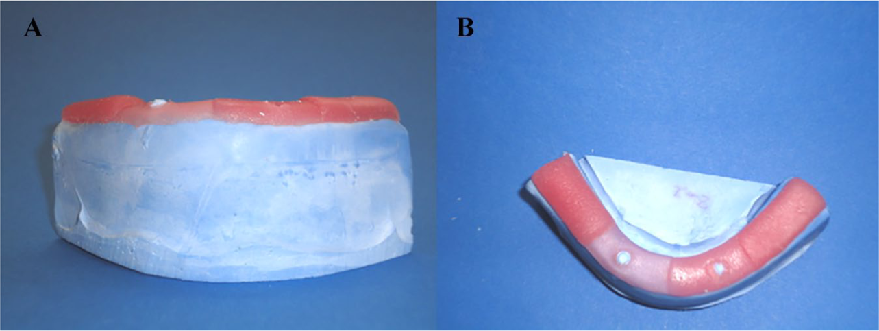
(A) Frontal and (B) Occlusal view of different mucosa heights during preparation by light-polymerized base plates which created gap for fluid-like elastic material for inner surfaces of the prostheses.
Standardization of dentition and prosthetics finishing procedures
Pink modeling wax was placed on the mandible model with the mucosa height base plate set and the artificial teeth were set up (Figure 4). Then, a silicon mold was made from this denture to standardize the tooth arrangement for all models. After the wax was removed with hot water, the mold in which the teeth were placed for a transparent acrylic (Orthoplast, Vertex Dental, Zeist, Netherlands) was polymerized by heat. The mucosa-formed gypsum model was placed into a silicon mold with hand pressure, and the overflows were removed and placed in a Biodent oven (Dikan 105, Mersin, Turkey) for 10 minutes at 2.5 bar at 55°C to polymerize the transparent acrylic. By using a transparent material in the construction of the prostheses, it was hoped that light would pass through the model in order to observe the stress lines.27,33 Ball and locator abutments were mounted on the models using a torque switch with a force of 25 Ncm (Astra Tech, Mölndal, Sweden). While the process kits were put on the locator abutments, titanium thread pieces were put on the ball abutments. Overdenture prostheses were fitted to the photoelastic models by adding transparent acrylic to the inner surfaces of the prostheses to accommodate the female parts. 35 They were then placed in the Biodent oven again for polymerization. To simulate the mucosa in the photoelastic model, a fluid-like elastic material (Gingifast; Zhermack SpA, Badia Polesine, Italy) was inserted into the gap created by the light-polymerized base plate on the inner surfaces of the prostheses, and prostheses were shaped to clearly view the stress lines around the implants during the photographing of the photoelastic models (Figure 5).
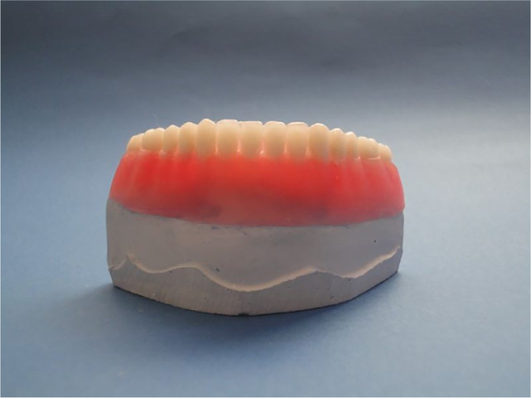
Standardized artificial teeth arrangement to use in all models. The impression was taken by this master model so that obtained guidance teeth model transferred to all other models from this master model to ensure standardization of all models.
Appearance of finished prostheses with mimic mucosa before occlusal loading on photoelastic models. Prostheses were shaped to clearly view the stress lines around the implants during the photographing of the photoelastic models.
Mounting of models in the polariscope device and loading
Before application of loading, all photoelastic models were checked by photograph using a circular polariscope to ensure that any stress-fringe was or was not in the models. 36 Mineral oil (Castrol, Istanbul, Turkey) was varnished on all models in order to facilitate photoelastic observation during evaluation. The loading process was carried out on a universal test machine (TSTM 02500, Elista Ltd., Istanbul, Turkey). A total of 135 N force was applied to the central fossa of both first molar teeth in the vertical direction.27,32 This load amount was chosen since it is close to the highest bite force measured in patients who use ISODs. 37 This loading region was chosen because it is located in the zone where chewing strength is highest in patients using ISODs, as the most effective elevator muscles are in this zone.27,32
The results of stress tests of the models were observed by a digital camera that was equipped with a macro lens (Macro Lens-Canon EF 100 mm F/2.8, Canon Inc. Headquarters, Tokyo, Japan) to obtain clear images (Canon EOS 650D, Canon Inc. Headquarters, Tokyo, Japan). A ring flash (Sigma EM 140 DG; Sigma Corporation, New York, USA) was used to prevent the beam from shading the image, and to ensure that the illumination of the photographed pattern was identical in each region. Models were kept at 50°C for 20 min in an oven to eliminate residual stress in the photoelastic models after each loading. 34 Before each installation, the models were examined in the polariscope device to make sure there were no stress accumulation lines. The stress concentrations and their sites were subjectively compared by the same evaluator. The following terminology was used to interpret stress intensity (number of fringes) in the polariscope under white light: 28
Low stress – 1 or 0 fringes,
Moderate stress – 2 or 3 fringes,
High stress – more than 3 fringes.
Results
Similar stress fringes were observed in terms of attachment types with the same alveolar bone level in each implant side; therefore, only the results from the right side are presented. However, both attachments’ patterns and implants with the different alveolar bone levels are presented from both right and left-side loading. Before occlusal loading, each model was examined to ensure that there was no residual stress.
Right-side loadings
Ball attachment 1 mm–1 mm abutment height model
Symmetrically moderate stress values were observed in the apical region of the implant on the force-applied side. The mesial coronal region of the implant had a moderate stress spread over a large area. Moderate stress was observed in the mesial apical region of the contralateral implant. Mid-span moderate stress was observed in the coronal distal region (Figure 6(a)).
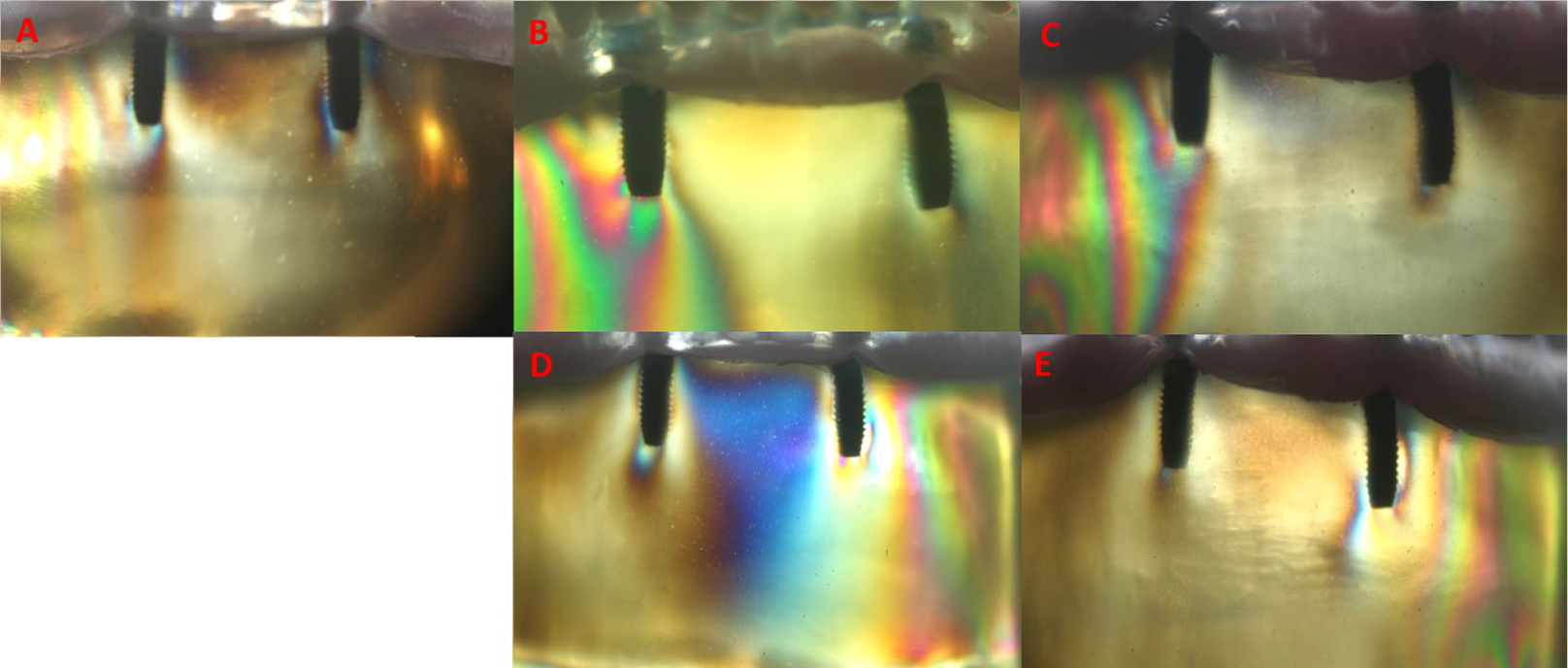
(A) Stress patterns of ball attachment 1–1 mm loading from right side. (B) Stress patterns of ball attachment 1–2 mm loading from right side. (C) Stress patterns of ball attachment 1–4 mm loading from right side. (D) Stress patterns of ball attachment 1–2 mm loading from left side. (E) Stress patterns of ball attachment 1–4 mm loading from left side.
Ball attachment 1 mm–2 mm abutment height model
At the right apical side of the implant, the mesial and distal regions were found to have moderate stresses, while the collar region had low stress. Low stress was observed distal to the apical side of the contralateral implant, and low stress was also found in the mesial aspect (Figure 6(b)).
Ball attachment 1 mm–4 mm abutment height model
In the apical region of the implant on the loading side, a moderate stress was observed symmetrically. Stress in the apical region spread widely from the distal side of loading implant to the alveolar crest. Low stress was observed in a very narrow area of the mesial apical of the contralateral implant (Figure 6(c)).
Locator attachment 1 mm–1 mm abutment height model
Moderate stress fringes were observed at the apical side of the loading side implant and at the mesial apical triplet, and low stress was observed in the distal coronal region. Moderate stress was observed along the mesial axis of the contralateral implant and at the distal apical area. In the apical region, a narrow field of moderate stress was observed (Figure 7(a)).
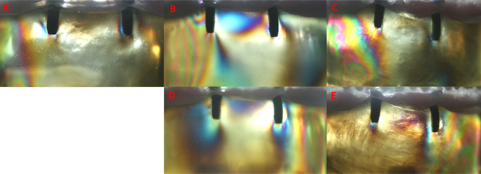
(A) Stress patterns of locator attachment 1–1 mm loading from right side. (B) Stress patterns of locator attachment 1–2 mm loading from right side. (C) Stress patterns of locator attachment 1–4 mm loading from right side. (D) Stress patterns of locator attachment 1–2 mm loading from left side. (E) Stress patterns of locator attachment 1–4 mm loading from left side.
Locator attachment 1 mm–2 mm abutment height model
Moderate stress was observed on the apical right side of the implant. In the distal middle triple zone moderate stress was observed, and moderate stress was also observed in the coronal region. Moderate stress was observed in the alveolar crest region between the two implants near the alveolar crest. Stress was observed moderately on the contralateral mesial apical triplet (Figure 7(b)).
Locator attachment 1 mm–4 mm abutment height model
Stress was observed moderately on the apical side of the implant on the loaded side. In the mesial apical triple, there was a moderate stress. Moderate stress was also observed in the apical of the opposite side of the implant. No stress was observed in the coronal regions between implants (Figure 7(c)).
Left-side loadings
Ball attachment 1 mm–2 mm abutment height model
Moderate stress value was observed at the apical side of the implant on the loading side. In the distal coronal region, moderate stress was observed. A moderate stress distribution was observed over a wide area between coronal regions of the implants. At the apical side of the contralateral implant, moderate stress was observed (Figure 6(d)).
Ball attachment 1 mm–4 mm abutment height model
At the apical left side of the implant, moderate stress was observed. Stress was observed in the middle apical triple region and moderate stress was seen in the distal apical triple and coronary when stress was detected (Figure 6(e)).
Locator attachment 1 mm–2 mm abutment height model
At the apical and coronal side of the implant on the side of loading, moderate stresses were observed. In the alveolar crest region between the two implants, medium stress was found spreading over a large area near the crest. Stress was observed moderately at the apical side of the contralateral implant (Figure 7(d)).
Locator attachment 1 mm–4 mm abutment height model
Moderate stress was observed around the implant on the side of the loading. At the apical side of the contralateral implant, a moderate stress event was observed (Figure 7(e)).
Discussion
In this study, the 1 mm–1 mm mucosa thickness models showed lower stress values than those obtained from models with 1 mm–2 mm and 1 mm–4 mm mucosal thicknesses. This difference was determined to be greater in the locator model than in the ball attachment model. As a further consequence of the study, in models with different mucosal thicknesses, more stress was observed around the implant which is on the force-loading side.
In the literature, stresses on implants in ISOD prostheses are usually determined by PESA.27-29,32-35,38,39 The photoelastic mandible model used in current study consisted of integration of the implants with the epoxy resin, which simulates the bone tissue and also impression material in the ISOD to represent the mucosa around the stud attachments.32,34
The absence of differences between cortical and trabecular bone, despite the resin being used to produce photoelastic mandible models with a modulus of elasticity similar to bone tissue, might modify the magnitude of the stress concentrations. However, neither the location of stress concentrations nor the behavior would be changed substantially. 32 Soft tissue elasticity differs depending on the amount of soft tissue and individual bone. In the ISOD model, such variables remain the same and can be controlled. 40 Thus, the analytical results help to make accurate predictions about implants and surrounding bone tissue.
In the present study, the resin was hardened in a silicone mold, as was done in other studies.27,34 The implants used were placed in acrylic models and then photoelastic resin models were prepared. This method aimed to prevent the stresses that might occur during the preparation of the nest in the photoelastic models. In many previous studies27-29,32-35,38,39,41 the mucosa around the implants located in the anterior region was eliminated, and artificial mucosa material was placed only in the posterior region under the prosthesis. This study was designed to provide conditions closer to the oral environment by using artificial mucosa to mimic material around the anterior implants.
Tanino et al. 42 investigated the load transfer of stress-relieving materials placed on two implants independently of each other using the FEA method. Again, Meijer et al. 43 studied loading conditions on overdenture prostheses with two independent implants using the FEA method. In both studies it was noted that the largest stress values were seen around the implant on the loading side. Similarly, researchers 44 have examined the effects of different attachment systems on the stress transmission of ISOD prostheses. In the distal region where force was applied, moderate stress development was observed, and very low stress occurred on the opposite side of where the force was applied. In this study, similar to the results of previous studies, the most intense stresses in unilateral loads were concentrated on the loaded side implant.
Both ball and locator systems used in the current study transmitted moderate stress to the implant–bone interface in all experimental models. This result is consistent with the study of da Silva et al., 45 who examined the stresses that different retention types transmitted to alveolar bone and implants. The O-ring attachment system transmits stress to the implants at moderate levels. Machado et al. 34 investigated the effects of the three different stud attachment systems on the stresses transmitted to the implants in implant-supported mandibular overdentures. Low levels of stress were found around the implants in the O-ring system. Fanuscu and Caputo 44 reported that, in the two different attachment systems examined, the force was transmitted to the implants in the maxilla overdentures, indicating that the ball attachment system caused stress transmission on the loading side at a high level. The results of our study are in disagreement with these two studies. Differences in the magnitude of the stresses in available literature investigations are thought to be dependent on the magnitude of force applied on models and the differences in the force application areas. It has been reported that the shift of the load site from anterior to posterior causes an increase in the stress of the toothless area and a decrease in stress in the implants.45,46
Ochiai et al. 33 reported that in a PESA study, low stress was observed in the loading side implant in the locator attachment system, while stress was distributed in the opposite side implants. Çelik and Uludağ 27 observed a higher stress level in the locator system than the ball system as a medium stress level. They again reported that the locator system distributed the stress in the opposite implant while the ball attachment system could not create it. The results obtained from this study support the results of studies by Ochiai et al. 33 and Çelik and Uludağ. 27 In all locator experiment models, the load was distributed on both implants, but more intense stress occurred in the loading-side implant. In ball attachment test models, lower stress intensity was observed in the 1 mm–2 mm and 1 mm–4 mm models on the opposite side of loading, regardless of loading site.
Hojo et al. 47 examined locator and extracoronal resilient attachment (ERA) attachment systems. They found that the ERA system showed minimal differences in stress transmission between implants under unilateral loadings. The results from our study were similar to theirs, as we found that the ball attachment system functions closely to that of the ERA; it did not transmit stress opposite the implants under unilateral loadings. In models with different mucosa thicknesses, the locator design was more stable and caused less stress on both the implants and the alveolar crest than did the ball attachment under unilateral loadings. For this reason, there was no gap between the male and female parts of the prosthesis provided with the ball attachment and the design of the retaining system. Applied force is therefore transmitted directly to the implants. When a resilient-type attachment such as a locator is used, under occlusal loads, the stress-reducing effect of the gap between the male and female parts reduces the forces directly transmitted to the implants. 19 Furthermore, mucosa support is more abundant in the locator holders, and some of the force can be transmitted through the mucosa to the alveolar crest at the loading point.
The highest stress concentration observed in the implants was due to the resilience difference between the implants (20–30 μm) and the mucosa (approximately 500 μm).48,49 Therefore, it increases stress values on more resilient mucosal implants.1,48
Recently, a study 18 compared ball and locator attachment systems using the FEA method in models with different bone heights independently around two implants that were supporting overdenture prostheses. The authors found lower stress values in the locator models than in the ball models. This result was consistent with those of our study. The authors suggested that this may be attributed to the dual retention mechanism (through both external and internal mating surfaces) of the locator attachment that provides vertical resiliency. The inside and outside mating areas provide more retention surfaces and thereby increase resiliency.50,51
In addition, it was explained that the ability of the denture cap to gently pivot in any direction over the male accommodates natural movements during occlusion and the pliancy of the soft tissue supporting the overdenture, possibly also providing additional resiliency. 52 Furthermore, when the bone height difference was 1 mm in the models (1 mm–2 mm), while observing the increase in stress, they found the lowest stress values in the models with 3 mm bone height (1 mm–4 mm) differences. Again, these results are partially compatible with our study. The authors believe this small difference is related to stimulation of the soft tissue which provided a more realistic approach in the current study. In the 1 mm–4 mm models, the stress value was lower than in the 1 mm–2 mm models (as with the previous study) but it was not the lowest of all the values, as in the previous study. This difference is thought to be due to the use of different analysis methods among the studies because of the lack of response of the biological system of finite element modeling.
For ISOD prostheses, the load under chewing forces is shared between the implants and mucosa that supports the prosthetic base. The amount of this sharing depends on the type of attachment and the thickness of mucosa. 53 When an occlusal force is applied to the implants vertically from a posterior point, a force component is formed in the anterior region, which causes the prosthesis to tend to be embedded toward tissue by rotating the axis passing through the implants. 54 Due to the anatomy of the alveolar crest, there is a tendency for the complete mandible denture to be pushed anteriorly under chewing forces. 53
It is unknown what proportion will be propelled by increasing the load and deformation of the resilient tissue that supports the prosthesis. As force is applied to the model, both deformations in the resilient material and stress values in the implants increase. This increase takes place gradually in relation to the characteristics of the resilient material. 53 When force is applied to the resilient material, the substance takes on a portion of the force, and changes shape by absorbing the energy.
The mechanical properties of an implant play an important role as they affect tissue healing and remodeling, and the importance of designing devices that mimic the replaced tissue is well evident. 55 The mechanical behavior clearly varies with the type of tissue, and anisotropy represents an important characteristic common to most biological tissues. Another important feature of most natural soft tissues, such as tendons, ligaments, and intervertebral discs, evidences a non-Hookean behavior; hence, their stress–strain curve is nonlinear, displaying a J-shaped region (compressive stress–strain curve).56,57
Biological materials are dynamic, complex, and multifunctional, characteristics which are difficult to achieve in purely synthetic systems. It was previously believed that artificial biomaterials had to be designed to provide a high strength associated with a high modulus of elasticity at low strain levels. However, in contrast to most artificial materials, soft tissues are characterized by a large amount of strain before failure, and they are flexible and tough, showing a high strength.58,59
Soft tissues exhibit viscoelastic behaviors such as stress-relaxation and creep, which show the ability of the natural structures to attenuate the stress concentration when they are strained, and to limit rapid deformations when they are subjected to high stresses. 58
Initially, when the deformation starts to increase with the application of force, the force applied at the same amount as the deformation reaches a certain level and does not produce the same amount of deformation as previously measured. After the substance is completely compressed, it starts acting as a solid substance and transmitts the force according to solid body principles. For this reason, it is expected that the graph showing the deformation caused by the application of the modeling force covered with a resilient material will show a parabolic curve. When the compression of the resilient material is completed, the force applied and associated deformation that occurs are directly proportional to each other.60,61 This information is thought to hold for mucosal material such as soft tissue in 1 mm–1 mm mucosa thickness and 1 mm–4 mm mucosa thickness models, whereas 1 mm–2 mm mucosa thickness models behave as soft tissue under force. The lower stress concentration in 1 mm–4 mm models can be attributed to their ability to behave as solid materials by compressing after a certain thickness of the soft tissues as described above, while higher stress is observed in 1 mm–2 mm models for both holder types than in other models.
Ichikawa et al. 48 argued that the difference between the soft tissue and the displacement angle of the implants may cause concentration of stress around the implant. Assunçao et al. 1 investigated the effects of ISOD prostheses with three different mucosa thicknesses (1 mm, 3 mm, 5 mm) and mucosa-assisted full dentures in stress transmission. The authors reported that the overdenture group showed higher stress values than did the full prosthesis group. When mucosal resilience and thickness increased in ISOD prostheses, these were found to increase maximal stress values. This stress increase was related to the increase in the load on the implants due to the decrease in prosthetic activity.
Our study offers results that are partially compatible with those of Assunçao et al., 1 who found an increase in stress when the mucosal thickness increased from 1 mm to 2 mm in both types of attachments, while stress values were decreasing in the models which had 4 mm mucosa thickness, as opposed to the previous study. This difference may be because the mucosa heights of the previous studies were symmetrical in both regions of the mandible, as in the present study, except that in the 1 mm–1 mm models, the mucosa thicknesses in the left and right side of the mandibula were different. Most likely in models with 1 mm–2 mm (which are thought to be a more efficient use of the soft mucosa characteristics), mucosa material under occlusal loads pushes the prosthesis anteriorly so that greater stress values are seen on the implants.53,60
Displacement of the oral mucosa supporting the prosthetic quadrant is greater than the resilience of materials used in in vitro studies. For this reason, the force transmitted to the implants is greater when sharing forces between implants and soft tissue in the mouth. Shigeto et al. 61 reported that prosthetic reinforcement is achieved by the residual ridge and the mucobuccal fold, and that load sharing occurs at different ratios at different crest heights.
In our study, the stress intensity was greater on the mesial and distal sides of the implants. This is similar to the results of Meijer et al., 62 who found that stress was concentrated on the mesial and distal sides of implants in overdentures supported by nonsplinted implants using the 2D FEA method. This may be because the mandible chewing forces in a denture made on independent supports force the implants to approach each other. Thus, stresses are transmitted equally to mesial and distal implants. 63
Since the magnitude of the forces that may result in destruction of implants or surrounding hard tissues is not known, it is useful to try to reduce the forces as much as possible 40 so that rehabilitation is long-lasting. The loading direction and size in in vivo conditions are very different from those of in vitro conditions. It is useful to plan in vivo studies to examine the effects of imitative variables in laboratory conditions.
Conclusions
Within the limitations of this study the following conclusions were drawn:
Regardless of mucosal thickness and attachment type, the implant on the loading side was subjected to the highest stress concentration.
In both types of attachments, the same average stress concentration was observed on and around the implants in the models of those implants having the same vertical height. In different height mucosa thicknesses (1 mm–2 mm, 1 mm–4 mm), locator attachment models distributed the load to the other side of the implant and its surrounding tissue, whereas the ball attachment did not.
The highest observed stress level was moderate for both attachment systems.
According to the results of this study, implants should be placed at equal bone heights and care should be taken to create equal mucosa thicknesses. If overdenture prostheses must be made on implants with different bone heights and different mucosa thicknesses after surgery, the choice of a locator attachment type (instead of a ball attachment) and selection of bilateral balancing occlusion (instead of unilateral balancing occlusion) will be positively affected by the prognosis of implants in relatively balancing the stresses transmitted to the implants.
Footnotes
Declaration of conflicting interests
The author(s) declared no potential conflicts of interest with respect to the research, authorship, and/or publication of this article.
Funding
The author(s) disclosed receipt of the following financial support for the research, authorship, and/or publication of this article: This research was supported by the project number 10202052 by Selcuk University Scientific Research Projects Coordinator.