
Abstract
Background
Wear and corrosion have been identified as two of the major forms of medical implant failures. This study aims to improve the surface, protective and tribological characteristics of bare metals used for medical implants, so as to improve scratch resistance and increase lifetime.
Methods
Hydrogenated amorphous carbon (a-C:H) films were deposited, using plasma enhanced chemical vapor deposition (PECVD), on stainless steel (SS), titanium (Ti) and niobium (Nb) metal plates. Nanomechanical and nanotribological responses were investigated before and after a-C:H deposition. Film thickness and density were quantified through X-ray reflectivity, and surface morphology before and after deposition were measured using atomic force microscopy, whereas the tribomechanical characteristics were probed using instrumented indentation.
Results and conclusions
Films of approximately 40 nm in thickness and density of 1.7 g/cm3 were deposited. The a-C:H films reduce the roughness and coefficient of friction while improving the tribomechanical response compared with bare metals for Ti, SS and Nb plates. The very good tribomechanical properties of a-C:H make it a promising candidate material for protective coating on metallic implants.
Introduction
Metal implants experience different levels of wear and corrosion due to the mechanical and chemical environment at the implantation site and are, therefore, susceptible to various forms of failure mechanisms.1–7 In vivo corrosion is a limiting design constraint on implant longevity as it increases the risk of deterioration of the material mechanical properties, which could promote fatigue fracture or trigger the release of metallic debris that could contaminate surrounding tissue.8,9 Corrosion by-products such as metallic ions and particulates could alter the local tissue environment and cause adverse biological reactions that may accelerate premature implant failure.10,11
Over the years, there has been growing interest in developing ways to modify the materials’ surface properties in an attempt to minimize wear and corrosion and increase prostheses lifetime. Such interest has motivated the application of protective thin films on load-bearing surfaces for increased scratch and wear resistance.12–15 The use of amorphous carbon (a-C) for biomedical applications has recently received wide attention due to its ideal material properties, which include excellent wear protection, corrosion resistance, and biocompatibility.16,17 a-C comprises a mixture of sp2 and sp3 carbon bonds, and hydrogen is frequently present in amounts up to 40 at.%, occupying regions of low electron density in the matrix, and delivering a hydrogenated version of amorphous carbon (a-C:H). The deposition method and its characteristics control the microstructural details of the material, including the hydrogen content and carbon hybridization ratio, which subsequently strongly influence its physical, mechanical, and tribological response.14–18 a-C and a-C:H coatings are well known for their high hardness, low coefficient of friction, uniform adherence, abrasion resistance, thermoresistance, and chemical stability.16,17,19,20 These characteristics can improve tribological properties at the contact region and allow an increase in prostheses lifetime, avoiding body rejection from the adjacent host tissue.
Such surface coating technology has obvious biomedical applications, including, but not limited to orthopedic, cardiovascular, and dental implants.21–24 The use in joint design for total hip and knee arthroplasties is self-evident due to the large loads that must be transferred via articulating surfaces operating in a harsh biological environment. 12 a-C thin films have been explored as a means for eliminating issues related with femoral head fractures and wear on load-bearing surfaces, that may result in bone resorption and aseptic loosening of the prosthesis, with some highly encouraging results.23,25,26 Cardiovascular implants are hindered by post deployment complications such as biocorrosion and structural failure,27,28 which can induce platelet activation and initiate thrombosis. 29 Also, changes in blood flow patterns associated with implant deployment include large-scale vortex formation and flow stagnation, which may enhance the deposition of platelets in the acute stages of implantation. 30 Several studies evaluated the in vitro and in vivo performance of a-C coated stents and mechanical heart valves.31–34 They have concluded that the coating may contribute to a reduction in thrombogenicity by suppressing platelet adhesion and activation, and in inflammatory response by minimizing the release of cytotoxic metal ions. Additionally, a-C coating has been shown to improve the corrosion resistance behavior of titanium and Ti6Al4V alloys for dental implants, 24 as wells as to serve as a galvanic corrosion barrier between dental implant abutments and nickel-chromium superstructures. 35
Although numerous studies have indicated the excellent potential for a-C in biomedical applications, the findings have been variable in terms of material substrate, deposition method, and coating characteristics. Here, we provide a systematic characterization of the morphological, nanomechanical and nanotribological properties of three metallic materials, commonly used for the fabrication of orthopedic, cardiovascular and dental implants: stainless steel (SS), titanium (Ti) and niobium (Nb). Whether as bare metals or with a coating material, SS and Ti have been the most popular metals for biomedical applications due to their good mechanical properties and excellent corrosion resistance. Nb appears as a very promising alloying element that satisfies the prerequisites of biocompatibility and hemocompatibility, and that could substitute the cytotoxic nickel element from titanium alloys while retaining the key characteristics (i.e., shape memory effect, super-elasticity) of nitinol.36–38 The studied materials were subsequently coated with a-C:H, using a plasma-enhanced chemical vapor deposition system, and their nanotribological properties were investigated, to evaluate if a-C:H improves their performance.
Materials and methods
Metallic substrates
Metallic plates were purchased from Goodfellow Cambridge Ltd. Stainless steel (SS), titanium (Ti) and niobium (Nb) metal plates (1 cm x 1 cm) were examined, pre-and post-coating deposition, for their topographical and morphological characteristics using an atomic force microscope and a scanning electron microscope, respectively. Furthermore, the materials were tested for their nanomechanical and nanotribological properties using an instrumented indentation platform, from which the hardness, elastic modulus, and coefficient of friction were extracted.
Synthesis of a-C:H films
Films of a-C:H were deposited on SS, Ti, and Nb substrates using a plasma-enhanced chemical vapor deposition system (PE-CVD). A radio frequency (RF) source is used to ionize the gas mixture introduced in the chamber, here CH4 and Ar in the ratio of 6 standard cubic centimeters per minute (sccm)/0.5 sccm. The generated ions are subsequently accelerated towards the metallic substrates by controlling the voltage on a grid situated between the ion source and the substrate material. All depositions were performed at room temperature using a chamber working pressure of 1.8 x 10⁻³ mbar while the basic pressure was 8 x 10⁻⁷ mbar, an RF power of 200 W, and a grid voltage of 150 V, resulting in a-C:H films with densities on the order of 1.7 g cm–3.
Microstructural characterization
The surface topography of the substrates and the deposited films was studied using atomic force microscopy (AFM) images obtained at room temperature and controlled humidity (~30%) using a scanning probe microscope (Ntegra Prima, NT-MDT) equipped with an NT-MDT probe (CSG10) having a mean force constant of 0.11 N/m and a nominal tip radius of 6 nm. Images of 10 μm × 10 μm were collected in contact mode with a tip scan rate of 1 Hz and resolution 512 × 512 points. Data were subsequently software-analyzed for extracting the root mean square (RMS) roughness of the surfaces.
The density and thickness of the deposited a-C:H film was quantified through X-ray reflectivity measurements (Rigaku Ultima IV). The X-ray was generated from a Cu tube using 3 kW. The collected reflected intensity at various incident angles was contrasted with a layered model from which the density and thickness of the a:C-H films was fitted. The experimental reflectivity curve for an a-C:H film together with its respective model best fit, simulated using Parrat’s formalism of the Fresnel equations, are shown in Figure 1(a).39,40 The inverse process of a-C:H properties extraction was performed using Rigaku’s Ultima IV software, GlobalFit. The accuracy of the XRR measurements is expected to be on the order of 1 nm and 0.1 g/cm3 for thickness and density respectively.41,42
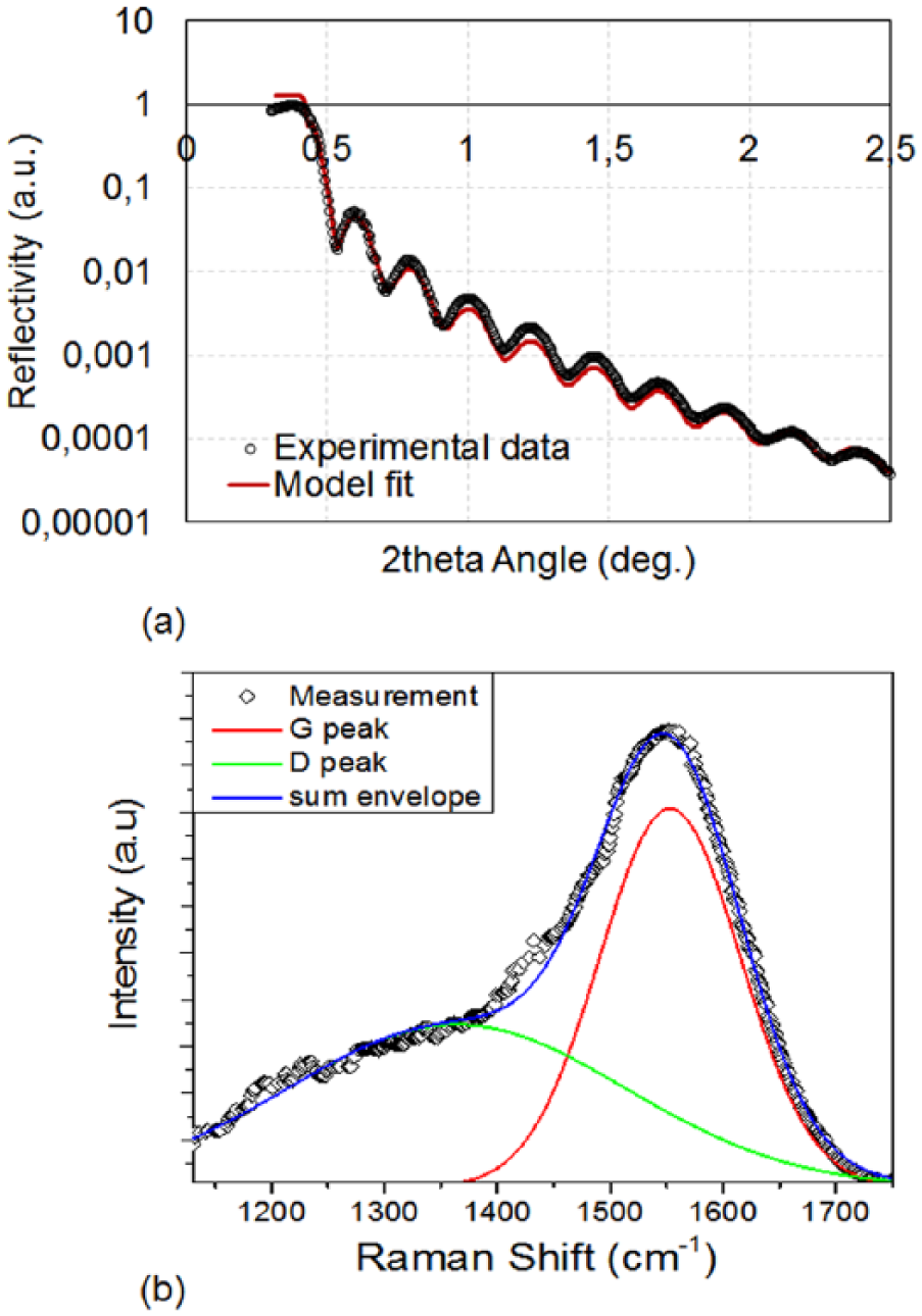
(a) X-ray reflectivity data and model fit on the hydrogenated amorphous carbon (a-C:H)-coated silicon substrate for density and thickness determination purposes. (b) Raman spectra of a thin a-C:H film on the Si substrate.
A confocal Raman spectrophotometer (LabRAM from HORIBA Jobin Yvon) with excitation wavelength of 441.1 nm (Kimmon Helium–Cadmium laser) was also used to characterize the structure of the a-C:H coating. Spectra in the range of 1000–2000 cm−1 were recorded by means of an Olympus BX41 microscope, coupled with a CCD detector (Figure 1(b)).
Nanomechanical and nanotribological characterization
The nanomechanical characterization was performed using an instrumented indentation platform (NanoTest, Micromaterials Ltd, UK). The metallic substrate samples were tested through load-unload ramps (single depth) using a diamond tip of the Berkovich type. During the indentation process the applied load (P) and the corresponding depth of penetration (ℎ) were continuously monitored with nanoscale accuracy: 100 nN for load and 0.1 nm for displacement. A maximum load of 100 mN was used. Ten indents (P−ℎ curves) at various locations on the metal plate surfaces were used for calculating the average elastic modulus (E), hardness (H), maximum penetration depth (ℎmax), plastic depth (ℎp), elastic work (Wel), and plastic work (Wpl) of indentation. The H, reduced elastic modulus (Er), and the plastic work ratio (
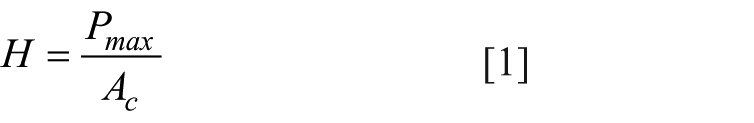
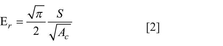
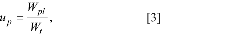
where Pmax is the maximum applied load, S is the unloading slope at maximum depth
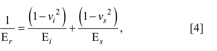
where E s , v s and E i , v i correspond to the elastic moduli and Poisson’s ratios of the material and indenter, respectively. In our experiments, a diamond Berkovich indenter is used with E i = 1140 GPa and v i = 0.07. With the exemption of A c , all other quantities were obtained experimentally from the P−ℎ response. The area of contact was estimated using the Oliver and Pharr methodology, in which A c is calculated as a function of experimentally obtained parameters. 43 The imperfect indenter geometry was taken into consideration through a calibration process that preceded all measurements. During the calibration process, a multi-depth experiment was performed on a material (fused quartz) with known mechanical properties (E = 69.9 GPa and H = 9.0 GPa), and, through an inverse analysis of Equation 2, the actual indenter geometry was calculated as a function of the indentation depth (A c = (ℎ)).
The nanotribological characteristics of the deposited films were studied using nanoscratch testing. 15 During a nanoscratch test, the investigated sample is moved perpendicular to the scratch probe while at the same time the contact normal load (P N ) is ramped at a pre-defined rate. Throughout the test, the probe penetration depth and frictional load (P T ) were continuously monitored. Figure 2(a) shows the loading profile during a scratch test, with a 3.2 μm end radius conospherical probe scanning over a 300 μm track at a scan speed of 2 μm s–1. A pre-scratch scan was carried out using an ultra-low contact force (0.1 mN) to assess baseline sample topography. The solid line in Figure 2(b) shows the on-load probe depth, which represents elastic and plastic penetration depth. After 50 μm, the load is ramped at 1.6 mN s–1 until a maximum force of 200 mN is reached. The dotted line in Figure 2(b) shows the residual (plastic) depth once the scratch load has been removed; both on load and residual depth profiles have been corrected for initial sample topography. Friction force measurements are carried out throughout the test, giving access to the evolution of coefficient of friction (COF) = P T /P N , an example of which is shown in Figure 2(c). Three scratch tests were performed on each sample with very good repeatability. The standard deviations for all extracted properties are reported below (see Tables 1 and 2), and their coefficients of variation were within reasonable values (3–15%). The nanoscratched samples were subsequently evaluated using a Quanta 200 (FEI, Hillsboro, Oregon, USA) scanning electron microscope (SEM) at various magnifications. The SEM images were used to correlate morphological features with nanomechanical characteristics.
Mean values of the extracted nanotribological characteristics of bare metal (uncoated) and a-C:H coated surfaces. a-C:H: Hydrogenated amorphous carbon; SS: stainless steel; Ti: titanium; Nb: niobium; COF: coefficient of friction.
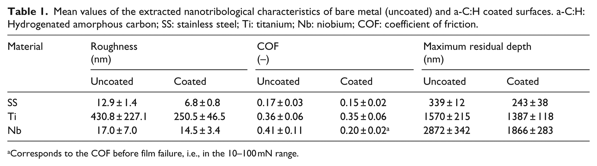
Corresponds to the COF before film failure, i.e., in the 10–100 mN range.
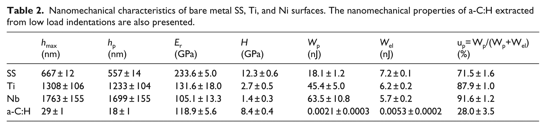
Nanomechanical characteristics of bare metal SS, Ti, and Ni surfaces. The nanomechanical properties of a-C:H extracted from low load indentations are also presented.
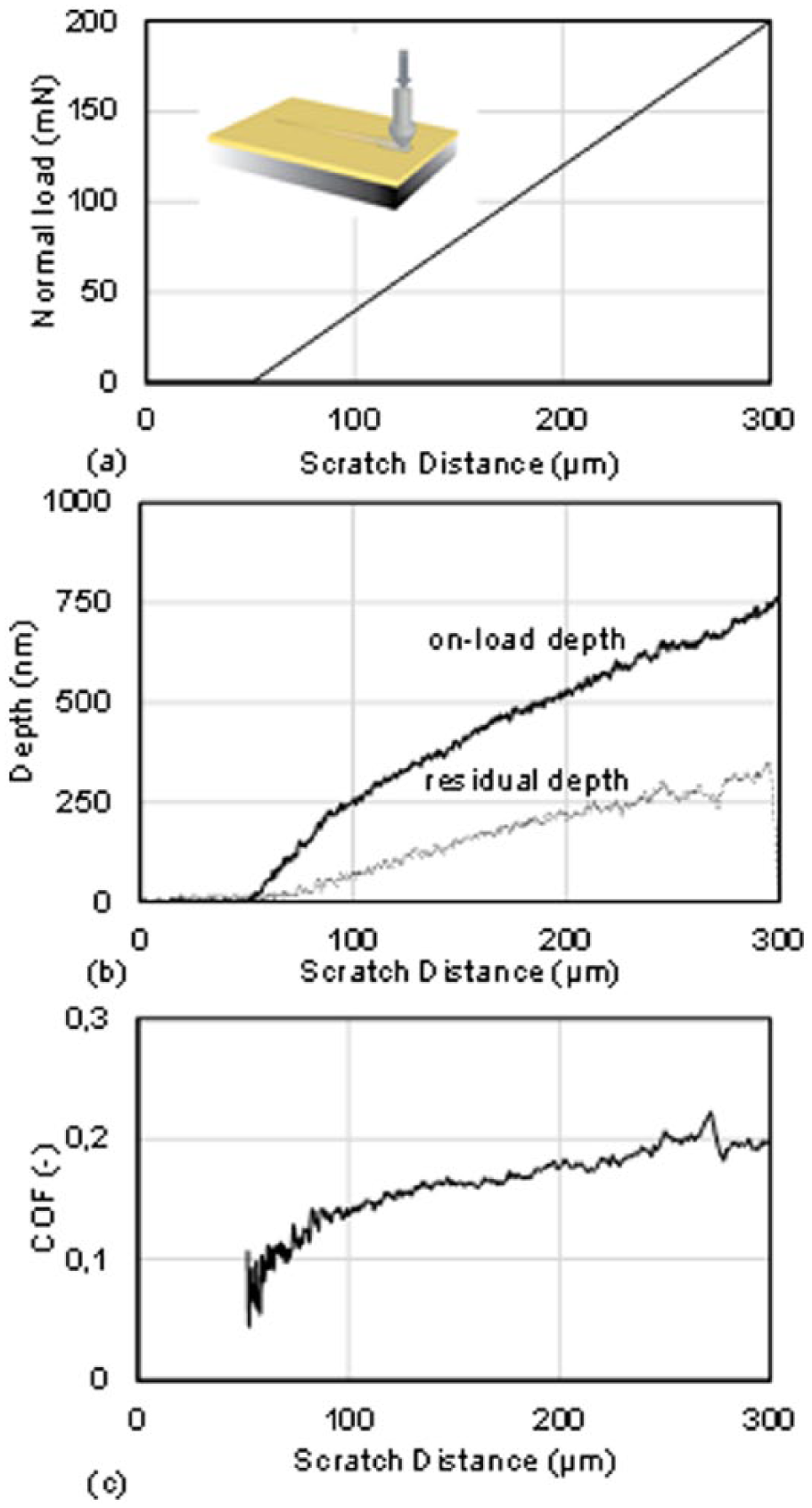
A typical nanoscratch test on SS bare metal. (a) Load profile. (b) On-load (solid line) and residual (dotted line) depth profile. (c) Coefficient of friction (COF) evolution with scratch distance.
Results and discussion
Morphological and microstructural characteristics
Figure 3 shows 10 μm × 10 μm AFM images of bare (uncoated) and a-C:H-coated SS, Ti, and Nb surfaces. The bare metal SS specimen was mechanically abraded and polished in successive steps of increasing grit until nanoscale roughness was achieved (12.9 ± 1.4 nm). The Ti and Nb specimens were left in their delivered surface conditions (430.8 ± 227.1 nm and 17.0 ± 7.0 nm, respectively) to investigate coating performance on native (unpolished) surfaces. Evaluation of the a-C:H coated specimens showed an approximately 2-fold decrease in surface roughness for the SS (6.8 ± 0.8 nm) and Ti (250.5 ± 46.5 nm) and a moderate decrease for the Nb (14.5 ± 3.4 nm) sample. The calculated RMS roughness for all coated and uncoated samples are reported in Table 1.
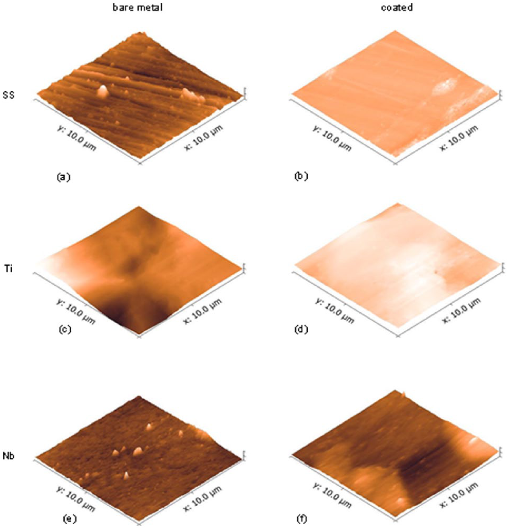
AFM images of uncoated and a-C:H coated stainless steel (SS), titanium (Ti) and niobium (Nb) surfaces. AFM: Atomic force microscopy.
X-ray reflectivity data and model fit on the a-C:H-coated silicon substrate, for density and thickness determination purposes, are shown in Figure 1(a). A silicon substrate wafer, with precisely known and homogeneous properties (surface roughness, refractive indices, mechanical properties, etc.) was used in this measurement in order to aid the simulation and fitting process (minimize the number of unknowns) and extract more accurate a-C:H film properties. The graph demonstrates that the experimental data fit the model well, and the resulting coating thickness was quantified at ~40 nm with a density value of ~1.7 g cm–3.
Raman spectroscopy was utilized to obtain information about the hybridization character of the deposited a-C:H thin films. Figure 1(b) shows the Raman spectra of a thin a-C:H sample on Si substrate. The major peak of the spectrum is assigned to the G band of carbon, which lies around 1550 cm−1 for visible excitation and the shorter hump at lower wavenumbers to the D band. The intensity, position, and width of the G and D peaks were determined from fitting the experimental spectra assuming Gaussian peak profiles. The ID/IG ratio, where ID and IG correspond to the intensity of D and G peaks, respectively, was found to be 0.32. The ID/IG ratio, along with the position of the G peak, were used as an indication of the sp3 / sp2 bonding fraction of the deposited films.
Nanomechanical response
The local mechanical properties of the metallic substrate samples were probed through nanoindentation. Typical P-h curves shown in Figure 4(a) were collected during load–displacement tests to a maximum load of 100 mN and loading/unloading rate of 10 mN s-1. All the derived nanomechanical parameters are summarized in Table 2. The corresponding data for the uncoated SS, Ti, and Nb surfaces are in line with the nominal mechanical properties of these materials, previously reported in literature. 44 The higher up values of Nb and Ti, compared with the SS alloy, denote materials with a greater ability to dissipate energy in plastic deformations, and thus less vulnerable to fracture and fatigue failure. Stainless steels are nowadays being replaced by more corrosion and fatigue resistant alloys, in permanent implants, such as Ti and Ti-Nb alloys. Nevertheless, the low cost of stainless steels has maintained their application in many temporary orthopedic devices, such as bone screws, bone plates, and intramedullary nails and rods. 44 Beyond substrate mechanical properties, Table 2 also summarizes the nanomechanical properties of the synthesized a-C:H as measured from low load (0.5 mN) indentations on an 80 nm thick film deposited on a silicon substrate. a-C:H possesses high hardness and elasticity, a low plasticity index, and a high H/E-ratio. This combination of properties exhibited by a-C:H is expected to enhance the tribomechanical performance of the coated systems and protect the metallic substrates, which have a higher propensity to plastic deformations (high up and low H/E values).
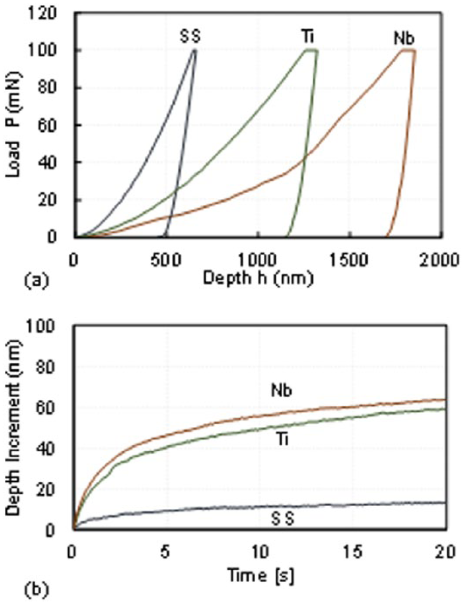
Nano indentation response of bare metal SS, Ti, and Nb surfaces. (a) Load–displacement. (b) Creep data.
The nanoindentation platform was also used to study the comparative creep responses between the three substrate samples; the resulting displacement-time data are shown in Figure 4(b). Creep relates to the tendency of materials for time-dependent deformation under the influence of a persisting stress that could even be below the material’s yield stress. Even though it is a typical response for all solids, it might eventually lead to failure. The Nb and Ti samples showed comparable creep deformations in both the primary and secondary stage. In contrast, SS quickly moves from a non-linear to a linear behavior, demonstrating the least indentation creep response. The superior creep response experienced by SS is, in part, related to the higher hardness of the material, which leads to a lower percentage of plastic deformation, and, subsequently, less susceptibility to time-dependent deformation. Nevertheless, the nanoscale deformations for all materials, which become saturated after several seconds, are of secondary importance for body temperature applications.
Nanotribological response
The nanotribological characteristics of bare metal and a-C:H coated surfaces were studied using nanoscratch testing. The nanoscratch responses of the SS, Ti, and Nb surfaces, and the evolution of friction coefficient are shown in Figure 5. In general, SS shows smooth depth and COF responses with scratch distance due to the flat surface finish and nanoscale roughness whereas the native surfaces of Ti and Nb lead to fluctuating responses; nevertheless, the mean response trends of all materials are similar. The response of on-load depth and residual depth with scratch distance increases for all specimens in response to the gradual increase of the normal applied load (Figure 2(a)). As expected, the on-load depth profile of the various materials investigated herein scales with their hardness (denoting resistance to penetration), whereas the residual depth scales with the plastic work ratio, which quantifies the tendency of the material to dissipate energy in the form of plastic deformations (see Table 1); Nb demonstrates the highest plastic capacity and lowest hardness, followed by Ti, and then SS. It is interesting to note that residual depths also scale inversely with the characteristic H/E-ratio of all materials (0.052 for SS, 0.021 for Ti, and 0.013 for Nb), demonstrating the importance of this parameter for tribomechanics. The steady state friction coefficient of the SS substrate is low (COF = 0.17 ± 0.03), in contrast to higher values calculated for Ti (COF = 0.36 ± 0.06) and Nb (COF = 0.41 ± 0.11). The COF values reported herein and in Table 1 reflect the average values for normal loads in the 1–100 mN range.
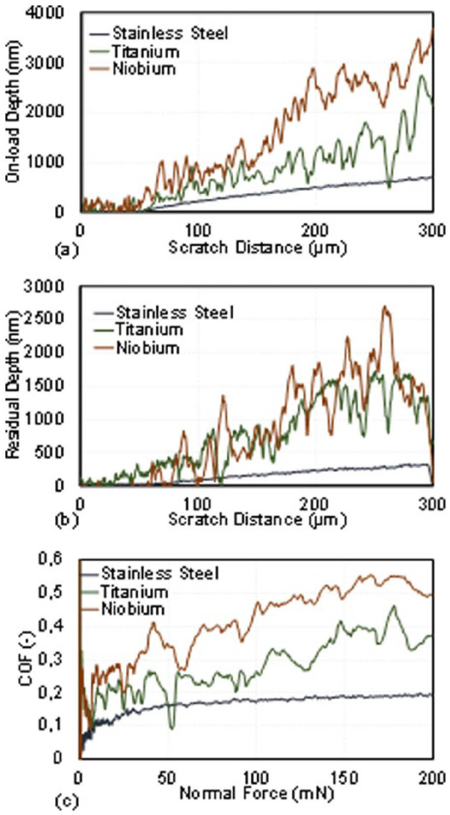
Nanoscratch responses of SS, Ti, and Nb surfaces on (a) load depth profile, (b) residual depth profile, and (c) COF evolution with applied normal load.
The effect of a-C:H coating on the nanotribological characteristics of the metallic surfaces are shown in Figures 6 to 8. Figure 6, in particular, demonstrates the capacity of the nanoscale film to reduce the plastic deformation and scratch propensity of the bare metal surfaces; the reduction being more evident in the case of SS. In all cases, the deposited film improved the tribological performance of the metal surfaces, reducing the maximum residual depth imprint: 28% reduction for SS, 12% for Ti, and 35% for Nb. In quantifying these reductions, the maximum values of residual imprints for the whole scratch distance were detected and averaged for all three scratch repetitions (average values and standard deviations are reported in Table 1). The interatomic bonds developing between the SS/Ti crystals and the a-C:H coating, compose stable structures with minor reduction in friction coefficient (Figure 7). On the contrary, Nb demonstrated a significant reduction in COF before the associated critical load (~100 mN) that led to film failure and delamination (see Figure 8(f)). The extracted nanotribological characteristics for all tested uncoated and a-C:H coated surfaces are listed in Table 1.
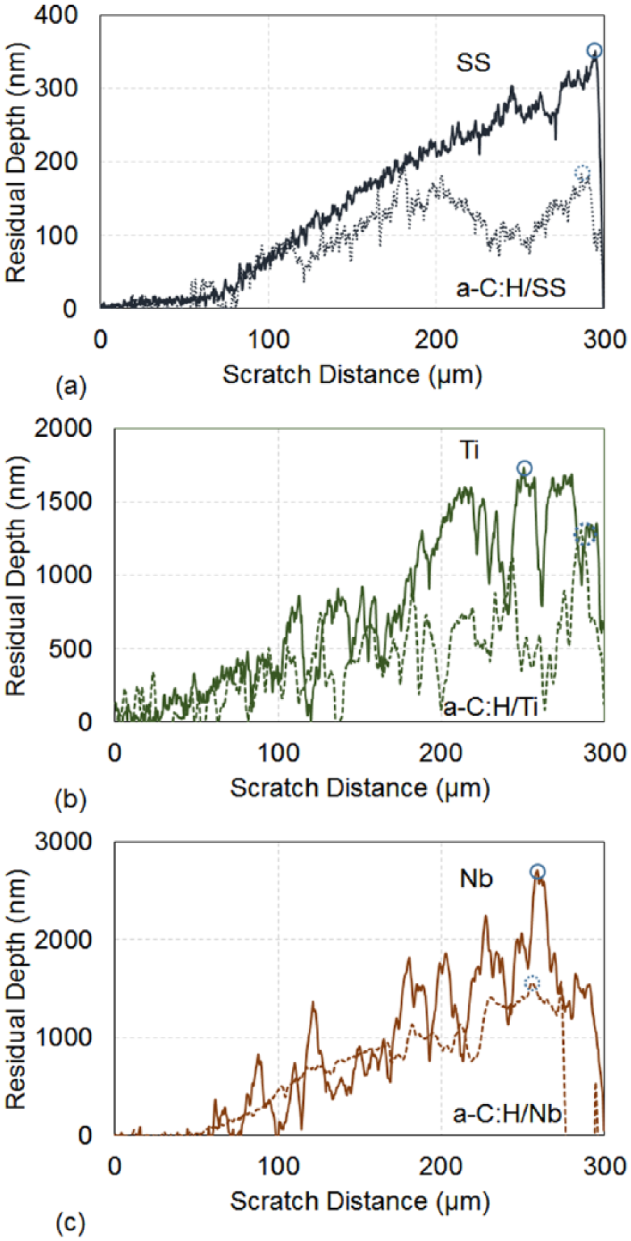
Effect of a-C:H coating on the residual depth response of (a) SS, (b) Ti and (c) Nb metals. Circles indicate the maximum values recorded for each test.
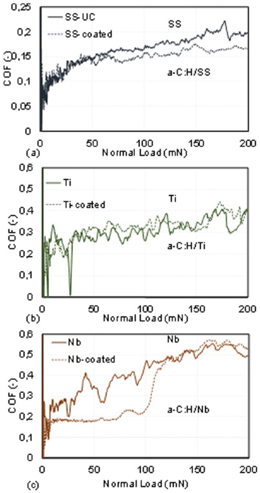
Effect of a-C:H coating on the COF response of (a) SS, (b) Ti and (c) Nb metals.
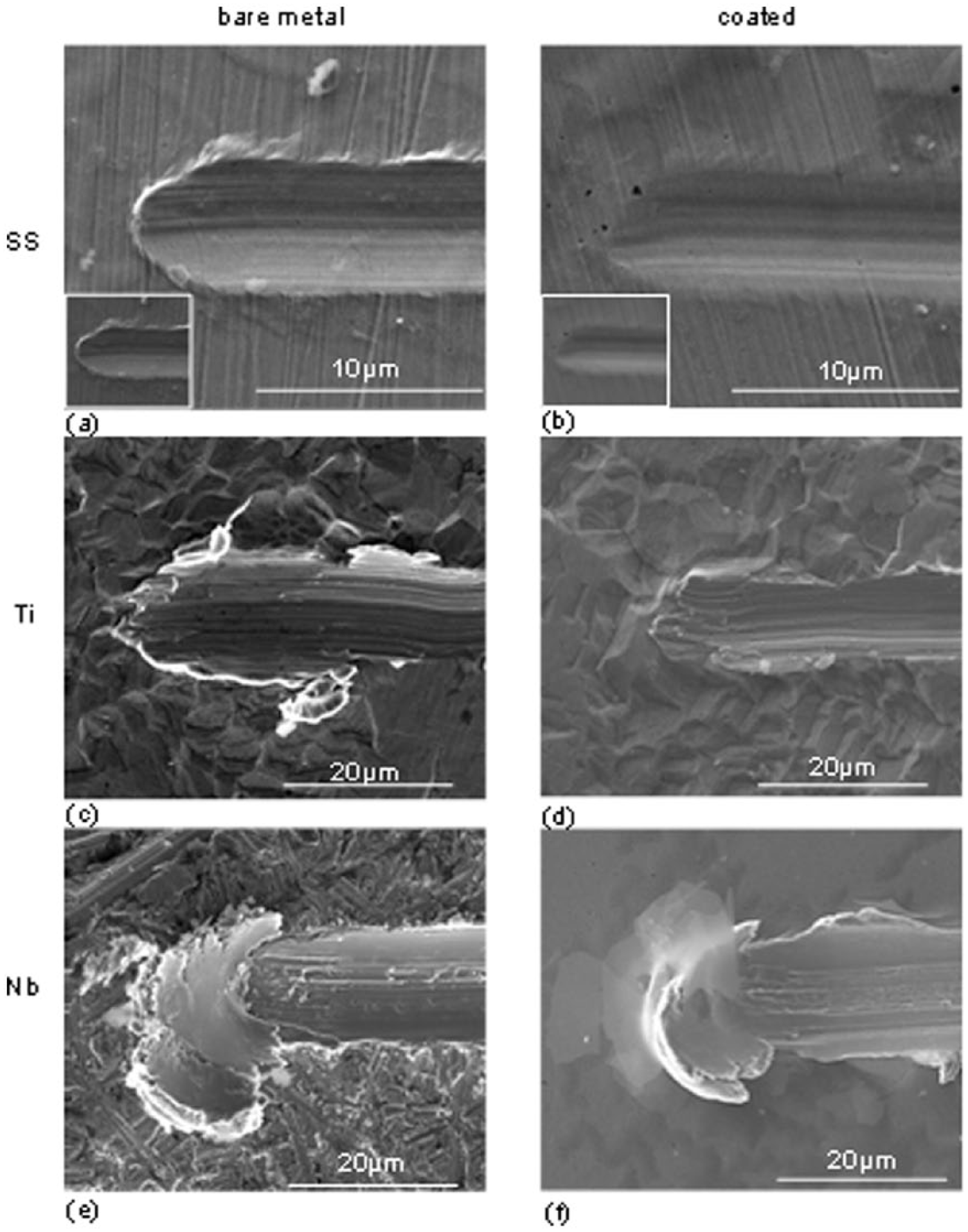
SEM images of residual scratched surfaces for the bare metal ((a), (c) and (e)) and a-C:H coated ((b), (d) and (f)) SS, Ti and Nb surfaces. Insets in (a) and (b) show the residual scratches at the same magnification (x6000) as the rest of the images for comparison purposes.
Figure 8 shows SEM images of the residual imprints left on the surface of the scratched specimens. By comparing the images of the coated metals (right column) versus the bare metal responses (left column), one can notice the reduction in size of the residual mark and wear volume, in line with the residual depth results presented in Figure 6. These enhancements are evident in all specimens, irrespective of whether the surfaces have been polished or left in their as-delivered state. The improvements in the tribomechanical response can be attributed in part to the reduction of friction between the indenter and the tested materials (Figure 7), and, in part, to the redistribution of stresses caused by the introduction of a hard, protective coating with higher H/E-ratio and subsequently improved elasticity/toughness (H/E for a-C:H is higher than all substrate metallic materials, 0.071). 45 The relatively uniform plastic deformations imparted on the a-C:H coated SS and Ti substrates indicate their enhanced tribomechanical response (Figure 8 (a)–(b)and (c)–(d)). Surface damage can be observed for Nb substrate at late stages of the scratch distance, which correlates with a critical load for film failure, as also evident from a discontinuity in the COF evolution (Figure 7(c)). As the contact load increases, plastic deformations are observed on the film followed by coating failure and delamination (Figure 8(f)).
Conclusions
The very good tribomechanical properties of a-C:H make it a promising candidate material for protective coating on metallic implants. Plasma-enhanced chemical vapor deposition has been effectively employed for depositing nanoscale a-C:H on SS, Ti, and Nb plates. The deposition of even a 40 nm thick film improves the tribomechanical response of these metallic surfaces as evidenced through nanotribomechanical tests. Residual imprints and surface wear have been reduced, most probably due to a slight reduction in the COF, a contact stress redistribution caused by the deposition of a hard, protective surface with enhanced H/E-ratio, which shields the substrate from plasticity and material removal during sliding. Despite the fluctuations of load during the tribomechanical testing of metallic surfaces left in their as-delivered state (non-polished), tribomechanical improvements can be observed on all specimens, which suggest that the efficiency of a-C:H coating is irrespective of whether the metallic surfaces are mirror polished or left in their native rough state.
Footnotes
Acknowledgements
The authors would like to acknowledge the European Regional Development Fund, the European Social Fund, the Cohesion Fund, and the Research Promotion Foundation of the Republic of Cyprus that co-financed, through the Strategic Infrastructure Project NEW INFRASTRUCTURE/STRATE/0308/04 of DESMI 2008, the infrastructure used within this work. The help of Prof. C. Varotsis with Raman measurements is greatly acknowledged.
Declaration of conflicting interests
The authors declare no potential conflicts of interest with respect to the research, authorship, and/or publication of this article.
Funding
The authors disclose receipt of the following financial support for the research, authorship, and/or publication of this article: European Regional Development Fund, the European Social Fund, the Cohesion Fund, and the Research Promotion Foundation of the Republic of Cyprus.