
Abstract
Background:
The resonant coil design is taken as the core technology in the magnetic coupling resonant wireless power transmission system, which achieves energy transmission by the coupling of the resonant coil. This paper studies the effect of the resonant coil on energy transmission and the efficiency of the system. Combining a two-coil with a three-coil system, the optimum design method for the resonant coil is given to propose a novel coil structure.
Methods:
First, the co-simulation methods of Pspice and Maxwell are used. When the coupling coefficient of the resonant coil is different, the relationship between system transmission efficiency, output power, and frequency is analyzed. When the self-inductance of the resonant coil is different, the relationship between the performance and frequency of the system transmission is analyzed. Then, two-coil and three-coil structure models are built, and the parameters of the magnetic field of the coils are calculated and analyzed using the finite element method. In the end, a dual E-type simulation circuit model is used to optimize the design of the novel resonance coil.
Results:
The co-simulation results show that the coupling coefficients of the two-coil, three-coil, and novel coil systems are 0.017, 0.17 and 0.0126, respectively. The power loss of the novel coil is 16.4 mW.
Conclusions:
There is an obvious improvement in the three-coil system, which shows that the magnetic leakage of the field and the energy coupling are relatively small. The new structure coil has better performance, and the load loss is lower; it can improve the system output power and transmission efficiency.
Introduction
Although by direct connection of metal wires traditional wired power transmission has good characteristics like high transmission efficiency, transmission stability, etc., this not only requires lots of copper, aluminum, and other conductive materials as a tangible conducting medium, but also can hardly keep pace with newer electronic products and high consumer demand. 1 Now, a non-contact power transmission technology – wireless power transmission (WPT) – has come into being. This can not only get rid of the need for a transmission conductive medium, but also save a lot of copper, aluminum, and other conductive materials.
According to its transmission mechanism, WPT can be classified as microwave/laser mode, inductive coupling mode, and magnetic coupling resonance mode. 2 The latter two modes are mainly used in the charging of mobile phones and other low-power intelligent electronic products. To some extent, technical means and the principles of the two modes are relatively similar. 3 The difference lies in their forms. 4
Early in the 19th century, Nikola Tesla from the United States had already carried out exploration and research in this area.5,6 Yet, because of the early electronic power technology and related materials, the experiments did not lead to substantial developments. In 2007, Professor Marin Soljacic at MIT proposed magnetically coupled resonant WPT technology in the journal Science, pushing WPT technology to a new high. 7 The technology has been recognized by many domestic and foreign researchers. Following this article, researchers actively carried out studies and developed theories, such as the coupling model theory 8 and the equivalent circuit model theory. 9 In recent years, WPT has been developed in many universities and in companies in developing countries, mainly concentrating on the improvement of power transmission and transmission efficiency. Some progress has been made.8–13
In order to further improve the transmission efficiency and transmission power of the WPT system, this paper takes the material copper as its research object, focusing on the transmission model and the WPT system, analyzing the effects of different coil structures and parameters on system performance, and the transmission performance of a simulation system, in order to provide a theoretical basis for the optimal design of a low-power WPT system.
System model and principle
According to Zhang et al., 4 the two-coil WPT system in the inductive coupling mode and magnetic coupling resonance mode have the same equivalent circuit, as shown in Figure 1.
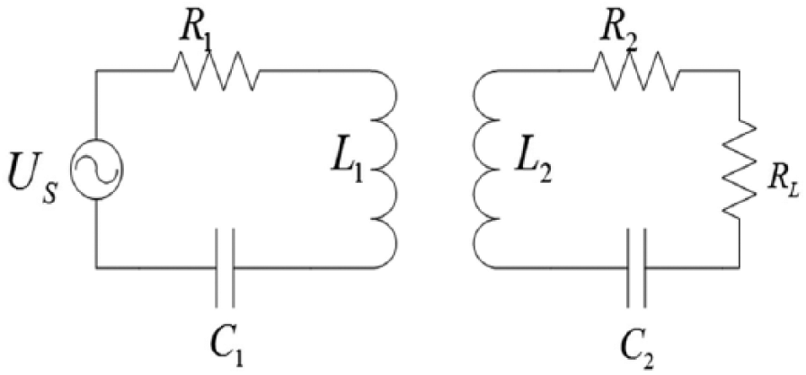
Transmission system equivalent circuit model.
In Figure 1,
According to Zhou et al.,
10
in the resonant WPT system, the frequency of the resonant circuit with
As known from the work of Li et al.,
11
in the resonant WPT system the maximum efficiency
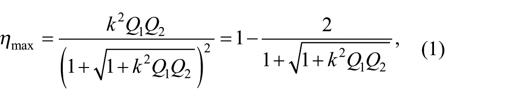
where
From equation (1), when
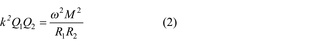
where
For one system that has a constant frequency,
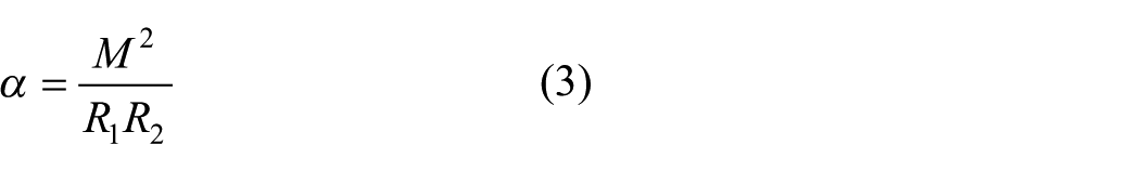
If we put equation (3) into equation (2),

Putting equation (4) into equation (1),
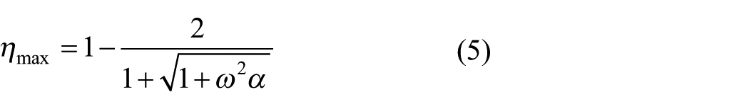
As shown in equation (5), the system efficiency
Performance effect analysis
There are a multitude of influencing factors in the WPT system performance. According to Tang et al.,
12
when the ratio
Effect of the coil coupling coefficient
Other parameters of the circuit are constant. When the coil coupling coefficient
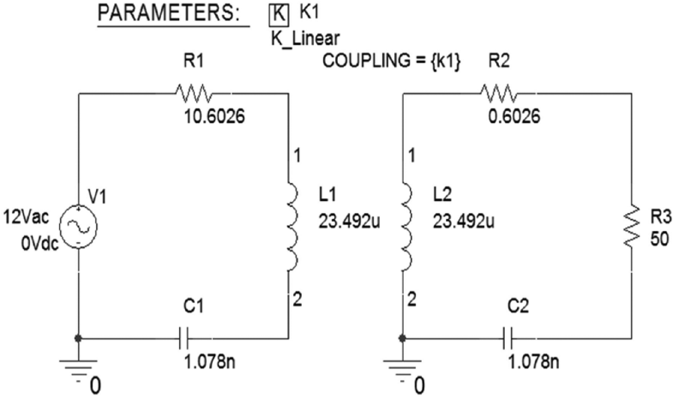
The circuit simulation diagram.
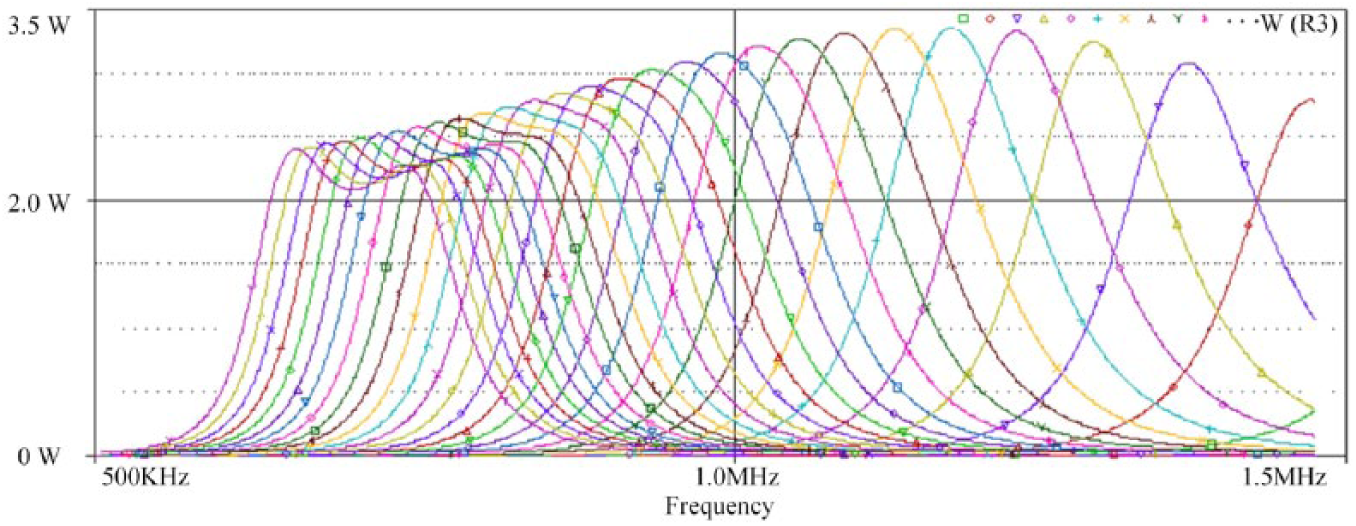
With the simulation circuit parameters set as shown in Figure 2, the resonant frequency of the system is set to 1 MHz. With the coupling coefficient variation in the range 0.01–0.31, and a stepping of 0.02, a total of 16 curves are obtained. In different coupling coefficients, using AC sweeping with the Pspice simulation circuit, a waveform curve of the system output power changing with the frequency is obtained (Figure 3).
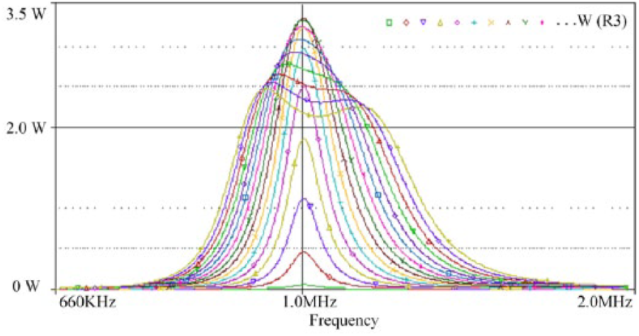
Different coupling coefficients: the output power changes with the driving frequency curve.
As shown in Figure 3, when the resonance frequency is 1 MHz, the output power of the system first increases and then decreases with the coupling coefficient. At the coupling coefficient of 0.15, the output power of the system reaches its maximum.
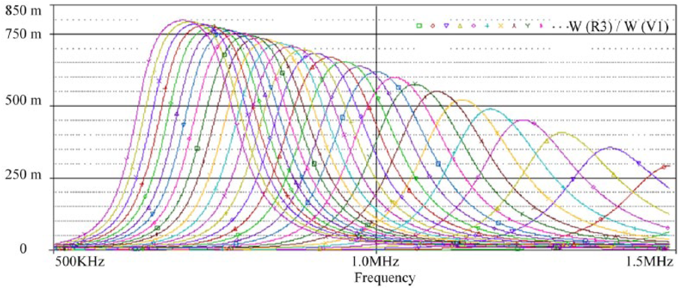
Figure 4 shows how the output efficiency of the system changes with different coupling coefficients.
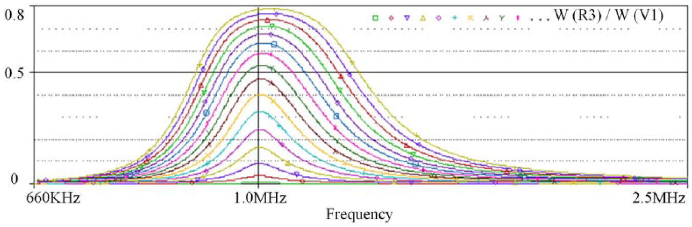
Different coupling coefficients: the output efficiency changes with the driving frequency.
Figure 4 shows that the output power will increase with the coupling coefficient when the system is at the resonant frequency.
Select the appropriate coupling coefficient for the resonant coil can ensure high output power and high transmission efficiency in the WPT system.
Effect of the coil self-inductance
To explore the influence of coil inductance L on the transmission characteristics of the system, the simulation circuit parameters are as shown in Figure 2, with other parameters fixed, and the load resistor
Different coil self-inductance: the output power changes with frequency.
As shown in Figure 5, the output power of the system first increases and then decreases with the self-inductance of the coil. When the self-inductance of the coil is 16 μH, the output power of the system is maximized.
As shown in Figure 6, the output efficiency increases with self-inductance. When the efficiency of the system output is at its maximum, the self-inductance is 60 μH, and the output power is 2.4 W. Thus, for a certain system, it is crucial to select the appropriate coil inductance.
Different coil self-inductance: the output efficiency changes with the frequency.
Modeling and analysis
Traditional resonant coil
It can be seen from the foregoing that when the parameter α is greater, the efficiency of the system output is greater. In order to ensure the equipment transfers energy within a certain range, a certain space volume in the magnetic field is required. Due to the various shapes of low-power electronic products, the structural characteristics of the resonant coil need to be considered. In view of the limited length of this article, only a two-coil structure and three-coil structure are researched. Using the electromagnetic simulation software Maxwell, a transceiver coil model is established, and the magnetic field distribution, self-inductance, mutual inductance, and resistance of the resonance coils are analyzed using the finite element method, looking at the transmission efficiency, energy transmission, and coil structure.
Two-coil structure
As shown in Figure 7, the resonant coils of the solenoid structure and the planar spiral structure are established in the electromagnetic simulation software Maxwell; the specific parameter settings are shown in Table 1.
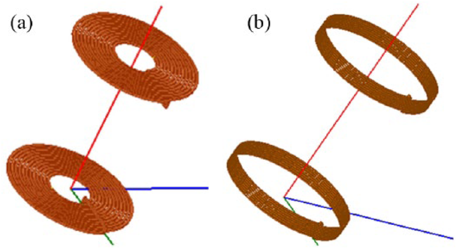
Planar spiral coil structure model (a) and the solenoid coil model (b).
Parameters of two-coil structure model.
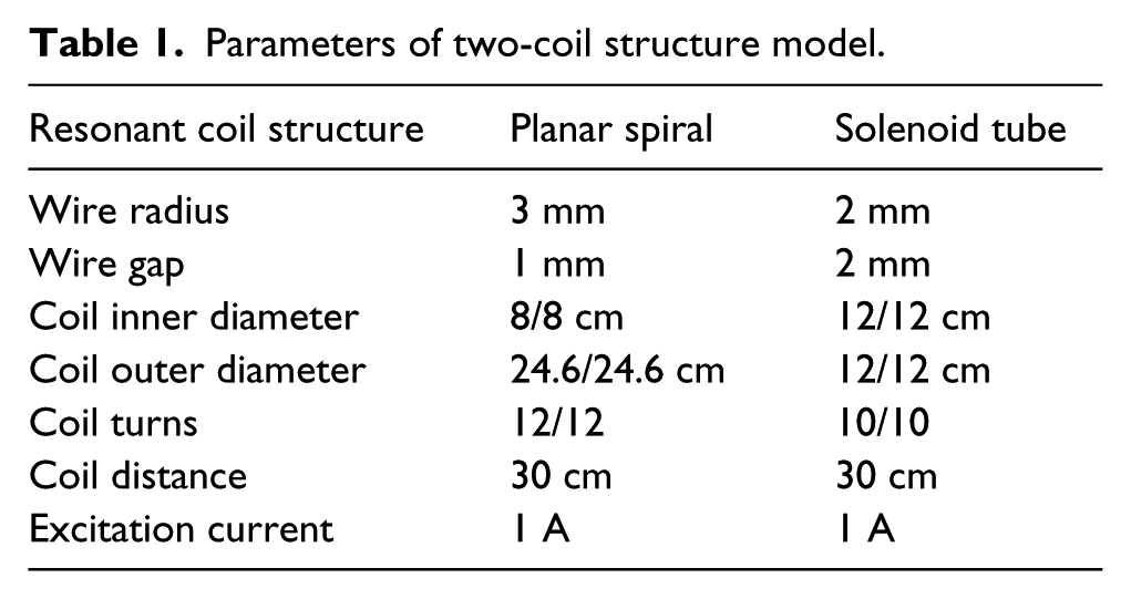
Figure 8 shows the distribution of the magnetic field intensity of the planar spiral structure resonant coil, and Figure 9 shows the distribution of the magnetic field intensity of the solenoid structure resonant coil.
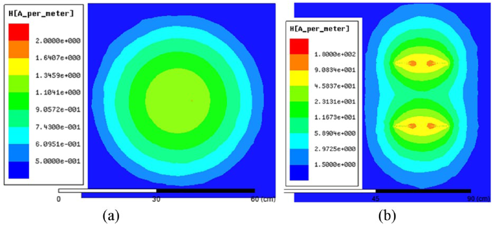
Z = 30, the magnetic field intensity distribution (a) and the magnetic field intensity profile in YZ (b) of the planar spiral resonant coil structure.
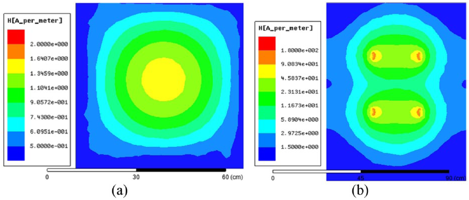
Z = 30, the magnetic field intensity distribution (a) and the magnetic field intensity profile in YZ (b) of the solenoid resonance coil structure.
Figure 8(a) shows that the magnetic field intensity generated by the planar spiral structure is greatest in the center of the circle, with a wide distribution; in contrast, the magnetic field intensity generated by the receiving coil is weak. The effective area of the magnetic field generated by the entire system is twice as large as the coil area. As shown in Figure 8(b), the energy coupling is uniform, but the magnetic flux leakage (MFL) area of the non-opposite resonant coil is large.
Figure 9(a) shows that only the magnetic field intensity of the receiving coil is relatively large, the magnetic field intensity of other regions is small. This illustrates that the effect of the energy transfer is noticeable. As shown in Figure 9(b), the energy coupling is uniform, but the MFL area of the non-opposite resonant coil is large.
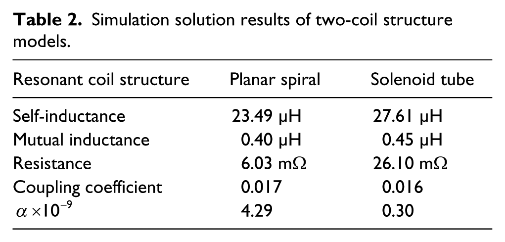
The results of the finite element analysis for the resonance coils in the Maxwell eddy current field are shown in Table 2.
Simulation solution results of two-coil structure models.
Three-coil structure
Using a three-coil structure mainly means adding a repeating coil between the transmitting coil and the receiving coil. The model established in Maxwell is shown in Figure 10. The magnetic field intensity distribution of the three-coil resonant structure is shown in Figure 11.
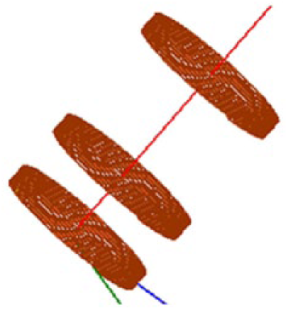
Three-coil structure model.
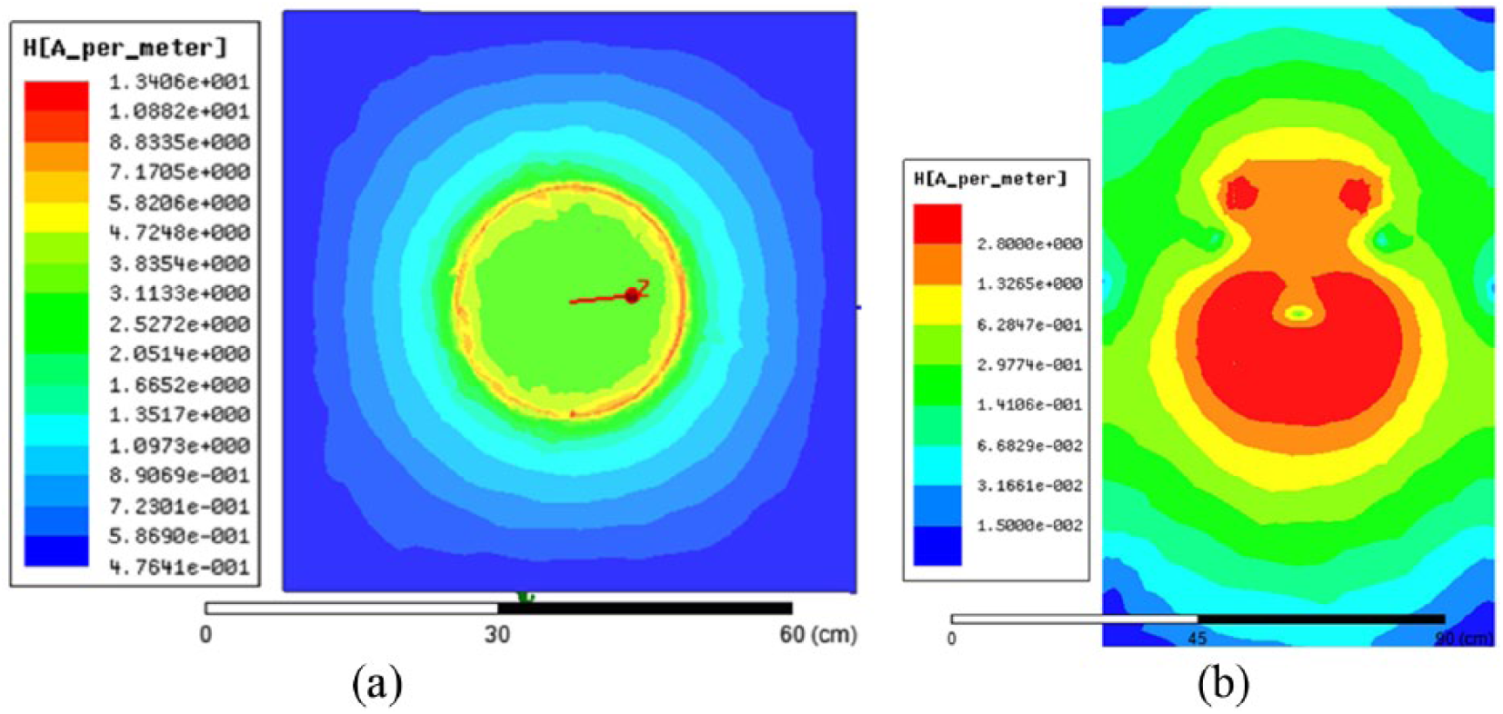
Z = 30, the magnetic field intensity distribution (a) and the magnetic field intensity profile in YZ (b) of the three-coil resonant structure.
Figure 11(a) shows that the magnetic field strength generated by the three-coil structure is greatest, with a wide distribution area in the center circle of the resonant coil; yet the magnetic field generated by the receiving coil is weak. The effective area of the magnetic field generated by the entire system is twice as large as the coil area. As shown in Figure 11(b), energy coupling is uniform, but the MFL area of the non-opposite resonant coil is rather small.
The coil inductance is initially calculated using the static magnetic field of Maxwell. Then, the transient model is established, and afterwards imported into the circuit diagram in Simplorer (Figure 12).
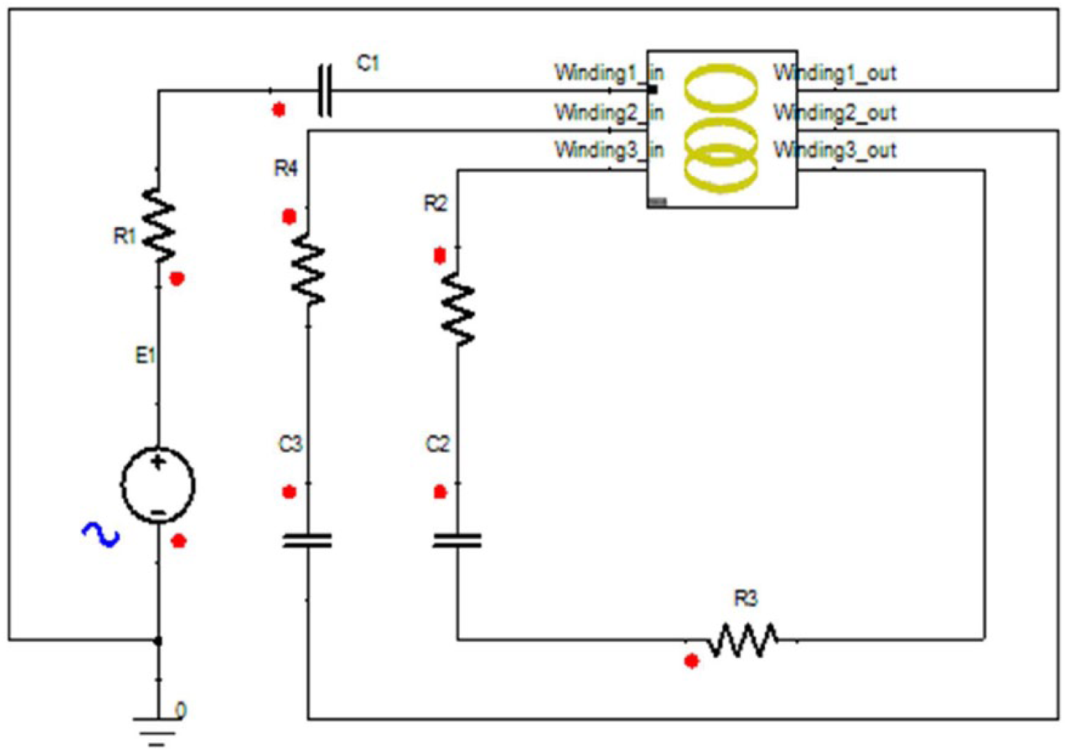
Co-simulation circuit.
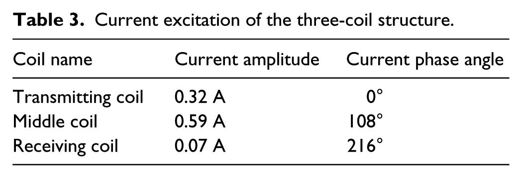
Current excitation of the three-coil structure.
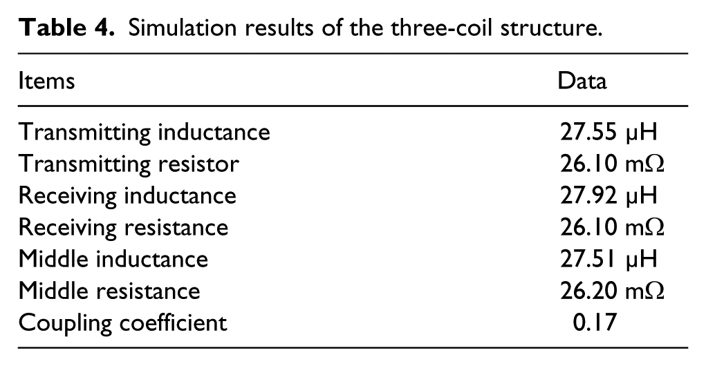
Simulation results of the three-coil structure.
As shown in Table 3, the phase of the excitation current of the middle coil of the three-coil structure is advanced, which causes the large magnetic field strength of the three-coil structure.
Comparing Table 4 with Table 2, the three-coil structure shows greater improvement on inductance, the mutual inductance, and the coupling coefficient, thus indicating that the three-coil structure has a great advantage in the transmission effect.
New resonant coil
Combined with the above research, the coil design and optimization steps are given as follows:
Determine the appropriate operating frequency.
Determine the coil material, to ensure the minimum internal resistance at this frequency, to improve the quality factor of the coil.
(Based on the simulation results, the shapes of the transmitting and receiving coils are preliminarily designed.
The coil model is established in Maxwell to solve the inductance, resistance, and coupling coefficient of the coil.
The system principle circuit diagram is set up in Pspice to determine the best coupling coefficient, the minimum coil internal resistance, and the optimal load value.
According to the simulation results, the coil is designed and optimized.
According to the design and optimization method of the resonant coil, a novel resonant coil structure is proposed, as shown in Figure 13.
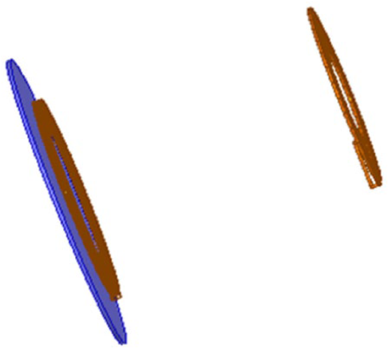
New resonant coil structure model.
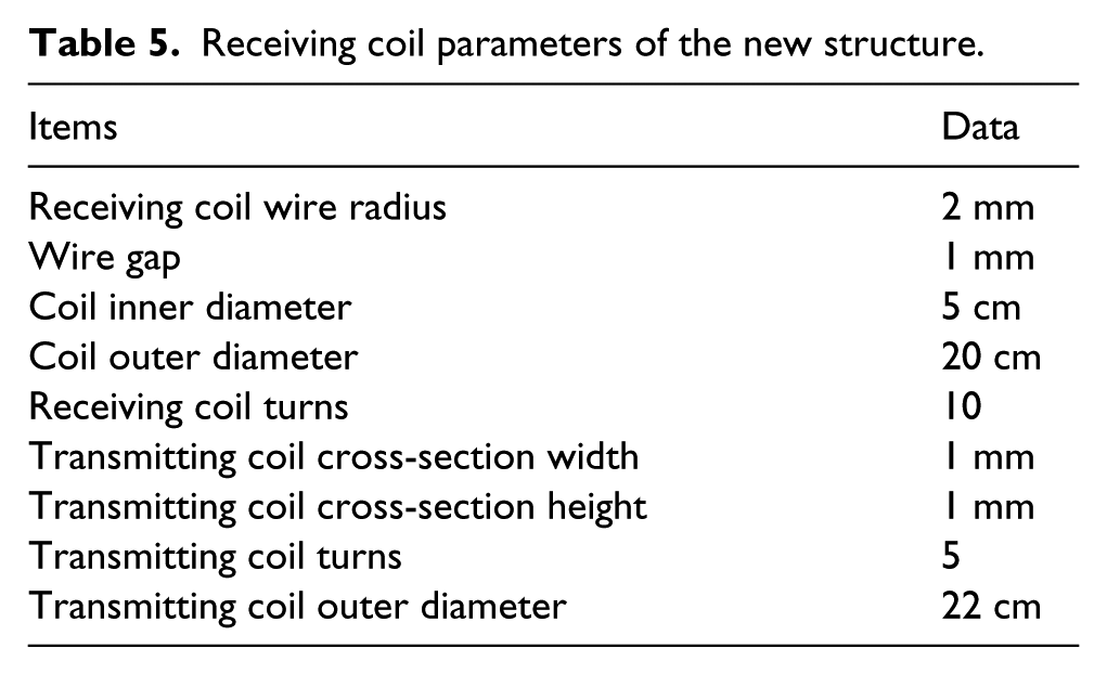
The dual E-type inverter circuit shows that the resistance of the transmitter has been determined, so it is not necessary to consider the launch coil resistance design. For the resonant coil system, the transmitter needs to provide the resonant coil with the strength of the MFL and magnetic field, so the transmitter selects the solenoid structure with the flat core. The coil internal resistance has an influence on the transmission of the whole system, so the receiving coil has a plane spiral structure. The resonant coil parameters shown in Table 5 are given by a large number of the coil simulation experiments, and the new coil structure and the traditional coil structure are compared and analyzed.
Receiving coil parameters of the new structure.
The power of the load resistor
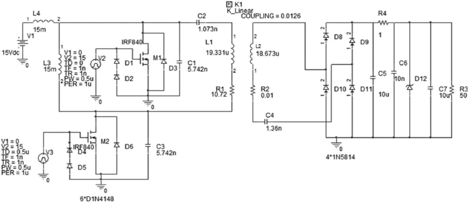
Simulation circuit model based on the new structure resonant coil.
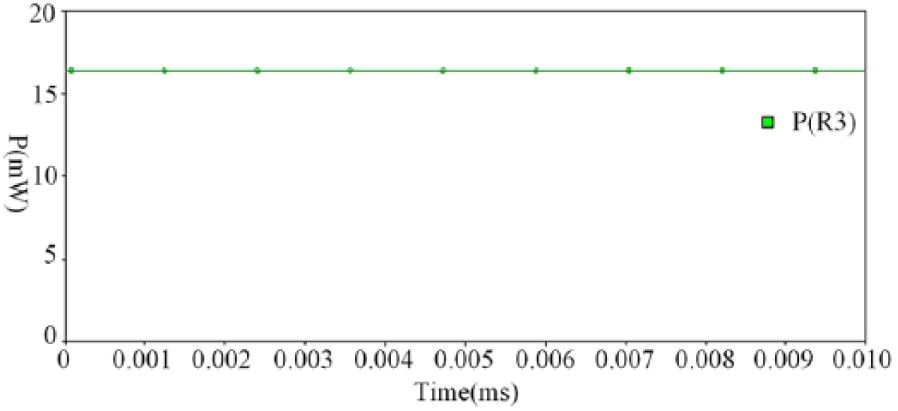
The power waveform of the load resistance of the new structure.
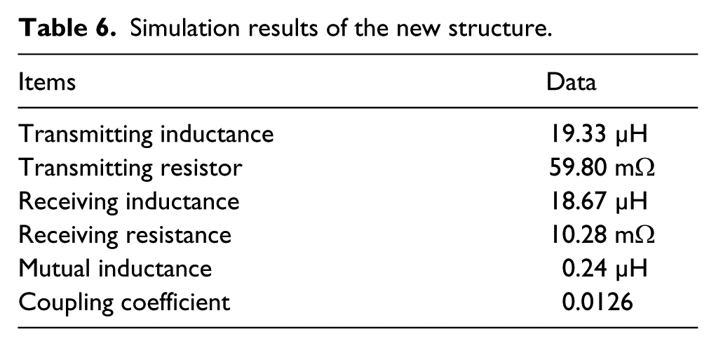
The parameters of the resonant coil are obtained by the eddy current field solver of Maxwell electromagnetic simulation software, as shown in Table 6.
Simulation results of the new structure.
Taking the resonant coil parameters into the Pspice circuit simulation model, the power consumption of the load resistance is shown in Figure 15.
As can be seen from Figure 15, the power consumption of the load resistance
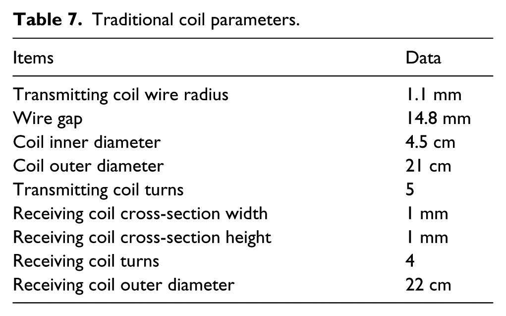
The parameters of the traditional multi-coil tandem structure are shown in Table 7.
Traditional coil parameters.
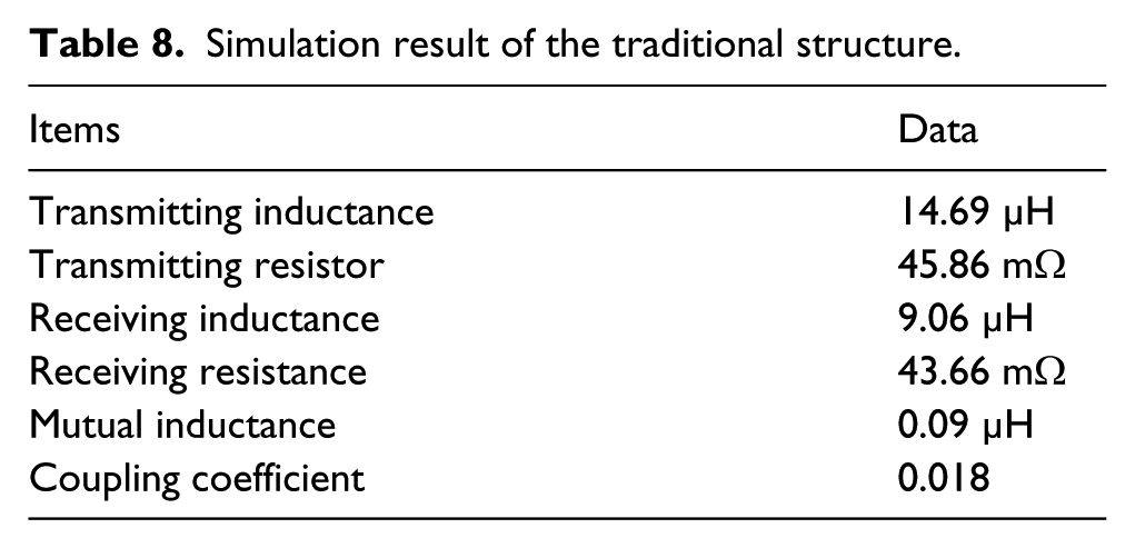
The self-inductance, coupling coefficient, and resistance of the resonant system are obtained using Maxwell, as shown in Table 8.
Simulation result of the traditional structure.
After the parameters of the traditional coil structure are updated, the power of the load resistor
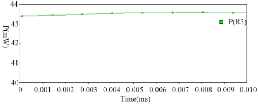
The power waveform of the load resistance of the traditional structure.
As can be seen from Figure 16, the power consumption of the load resistance
By comparing the designed and the traditional resonant coil at the same load resistance, we can see that the power consumption of the designed resonant coil is lower, which can effectively improve the power and efficiency of the WPT system.
Experimental results and analysis
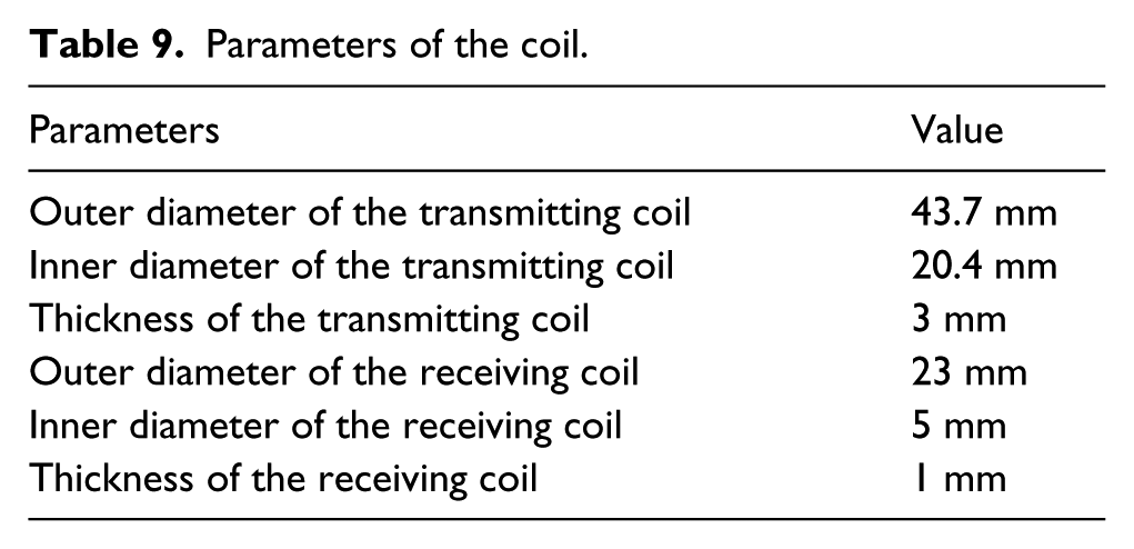
In testing the hardware, the resonant coil conforms to the Qi standard, as shown in Figure 17. The specific parameters of the resonant coil are shown in Table 9.
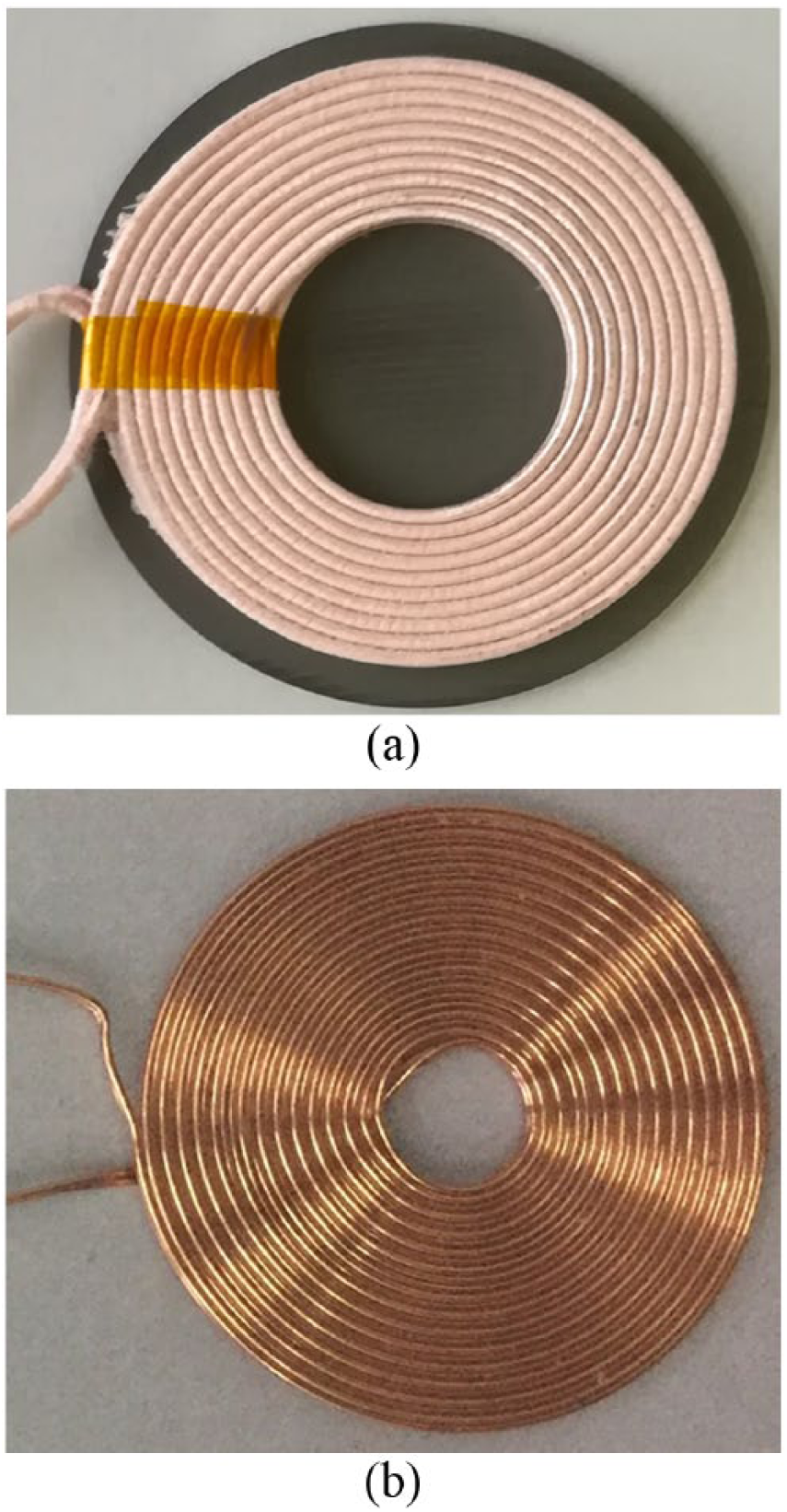
The transmitting coil (a) and the receiving coil (b), conforming to the Qi standard.
Parameters of the coil.
In this experiment, the system input voltage is 12 V, and the resonant circuit of WPT adopts the fixed frequency modulation mode. Figure 18 shows the coupling coefficient of the resonant coil under different operating modes: the constant current mode (CC mode), the constant voltage mode (CV mode), and the constant resister mode (CR mode). As can be seen from the graph, the coupling coefficient of the CC mode is obviously higher than that of the CV and CR modes. The coupling coefficient is close to 1 when the coil spacing is 1 mm; when the coil spacing is 9 mm, the coupling coefficient is 0.55. When the coil spacing is 1 mm in the CV mode, the coupling coefficient is the highest, which is 0.67. When the coil spacing is 1 mm in the CR mode, the coupling coefficient is the highest at 0.61. According to the data analysis, the coupling coefficient of the new structure coil performs well.
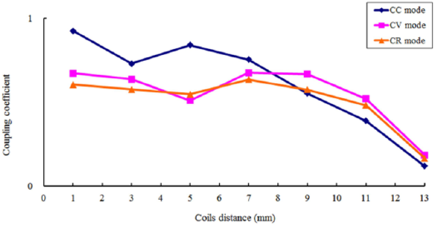
The coupling coefficient of the resonance coil under different operation modes.
Conclusions
This paper puts forward an efficiency factor
Footnotes
Declaration of Conflicting Interests
The author(s) declared no potential conflicts of interest with respect to the research, authorship, and/or publication of this article.
Funding
The author(s) disclosed receipt of the following financial support for the research, authorship, and/or publication of this article: This work has been partly supported by the Fundamental Research Fund for Heilongjiang Provincial Universities of China (grant number HDJCCX-201622), and by the Innovation Talent Research Special Foundation of Harbin Science and Technology Bureau of China (grant number 2016RQQXJ107).