
Abstract
Introduction:
This study aims to investigate the strength characteristics of fiber composites under uniaxial tensile stress.
Methods:
A tensile failure finite element model based on fracture mechanics was built for fiber composites. The principal stress concentration–release–transfer evolution and the crack propagation of the composites under the conditions of equal single fiber width, unequal quantity, and equal total fiber width and unequal quantity were discussed.
Results:
The tensile strength of the composites increased with fiber quantity when the width of each single fiber was equal.
Conclusions:
The tensile strength of the composites increased with fiber quantity when the total width of the composite fiber was equal.
Introduction
As a new type of structural material, fiber-reinforced composites have high specific strength and stiffness, fatigue and wear resistance, and safety. Therefore, fiber-reinforced composites are widely used in aerospace, national defense, civil construction, and other fields.1,2
Fiber composites present high strength and tenacity because the fiber restricts the expansion of matrix cracks. 2 The addition of fiber not only changes the distribution of the internal stress field, but also makes the instability and failure mechanism of the composites complex. 3 Many domestic and foreign scholars have extensively studied the mesoscopic damage mechanism and macroscopic damage performance of composites. Dunne and colleagues 4 studied the effect of different densities of an acrylonitrile butadiene styrene matrix on the tensile and impact strength and airflow resistivity of composites and proposed natural composite materials for automotive applications. Shokrieh and Moshrefzadeh-Sani 5 obtained the stress–strain curve of the whole damage process of composites through simulation using an incremental algorithm method, calculated the axial stiffness and strength of each layer by introducing the shear lag theory of Halpin–Tsai, and calculated the residual strength of the damaged layers by introducing the Tsai–Wu failure criterion. Vipulanandan and Guezo 6 studied the direct tensile behavior of polypropylene (PP) composite materials under different temperatures; on the basis of experimental results, constitutive models that incorporate strain rate and temperature were developed for predicting the yield strength, initial elastic modulus, and secant modulus at yield of the PP composites. Nazari and colleagues 7 presented an analytical model for predicting the fracture toughness of composites and concluded that this property of composites increases with an upward fracture toughness gradient of a propagating crack and vice versa. Das 8 studied the mechanical properties of jute fabrics and unshredded newspapers prepared in a polyester resin matrix and found that the tensile and flexural properties of hybrid composites are higher than those of pure paper-based composites, but lower than those of pure woven jute composites. Fang and colleagues 9 predicted the fatigue damage and residual strength of perforated layers and composites on the basis of continuum damage mechanics and discrete fracture models, and established the cracking and expansion of fatigue-driven delamination by inserting an interface layer with a certain thickness into the interface of each layer.
In the present study, a self-developed tensile failure finite element model for composites is built. Moreover, the effect of the number of fibers on the evolution of major principal stress and crack propagation is analyzed under two situations in which the width of a single fiber and the total width of fibers are unchanged. Furthermore, the relationship between the strength of the composites and the number of fibers is explored, and an effective analytical method is proposed for the research on the macroscale failure of composites.
Model and methods
Constitution
The calculation model uses a linear elastic two-dimensional plane stress constitution.
Tensile failure criterion of rocks
When the maximum tensile stress of some nodes inside the material is higher than the ultimate tensile strength of the material, the node ruptures.
The tensile fracture direction of materials is perpendicular to the direction of maximum tensile stress.
Program design process
A flowchart of the program calculation is shown in Figure 1. The displacement and stress fields are solved under the stress loading condition and then according to the maximum principal stress of the nodes to determine whether a cracking unit exists. Such a unit is then fragmented, and its information is corrected. Otherwise, the next time step is chosen or the calculation is ended according to the failure state of the specimen.
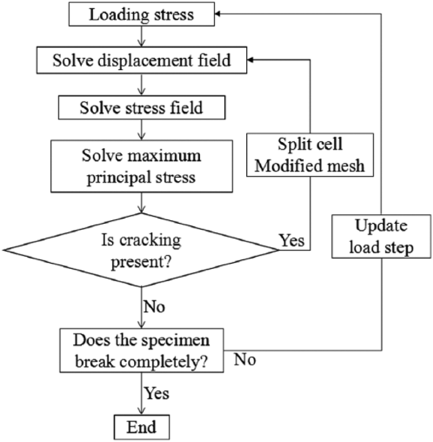
Flowchart of program calculation.
Numerical calculation model
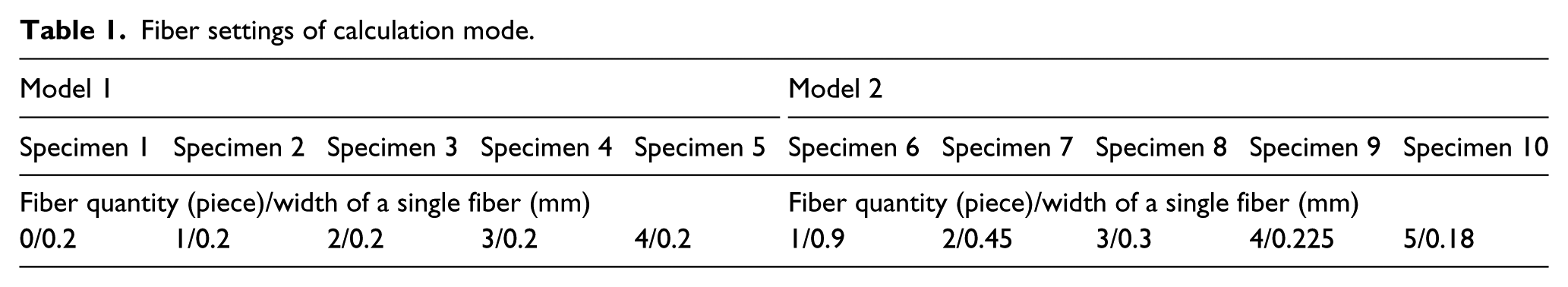
Two groups of models with a total of 10 groups of specimens are selected in the numerical simulation. The width of the fibers in the five groups of specimens in Model 1 is 0.2 mm, and the fibers vary in quantity. The total width of the fibers in the five groups of specimens in Model 2 is 0.9 mm, and the fibers vary in quantity. The specific numbers and widths of the fibers in the different specimens are shown in Table 1.
Fiber settings of calculation mode.
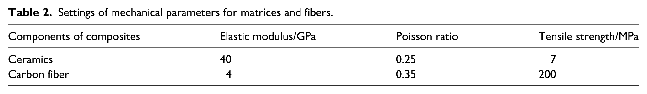
A schematic of the fiber composite model is shown in Figure 2. The specimens of the model are rectangular and consist of fibers and matrices; the matrices between fibers are inner matrices and the remaining ones are outer matrices. The size of each matrix is L × B = 8 mm × 3.2 mm. The fiber is a ductile material with length equal to that of the matrix. The width of b depends on the specific conditions of the different specimens. An equilateral triangle groove with a depth of c = 0.2 mm is arranged on the right and left sides of the outer matrices. Displacement constraints on the y direction are applied to the bottom side of the calculation model, and the tensile loading of vertical stress is adopted on the top portion. The model is divided into 8239 nodes and 16,115 triangular three-node units. The mechanical properties of the fibers and the matrix are similar to those of carbon fibers and ceramics, according to Zhang and colleagues.3,10 The setting of the mechanical parameters of the calculation model is shown in Table 2.
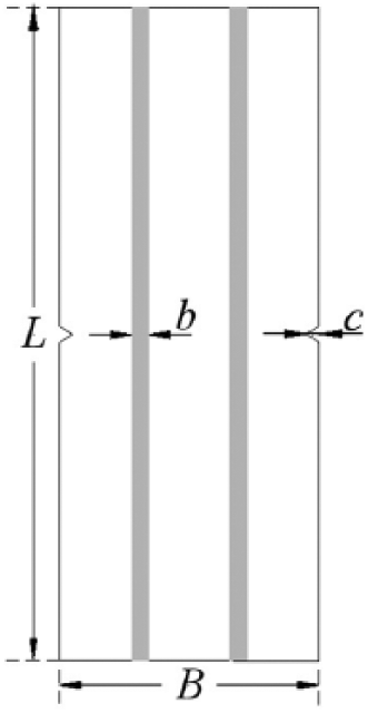
Schematic of numerical calculation model for fiber composites.
Settings of mechanical parameters for matrices and fibers.
Results
Results of numerical simulation for Model 1 and corresponding analyses
Evolution of major principal stress and crack propagation
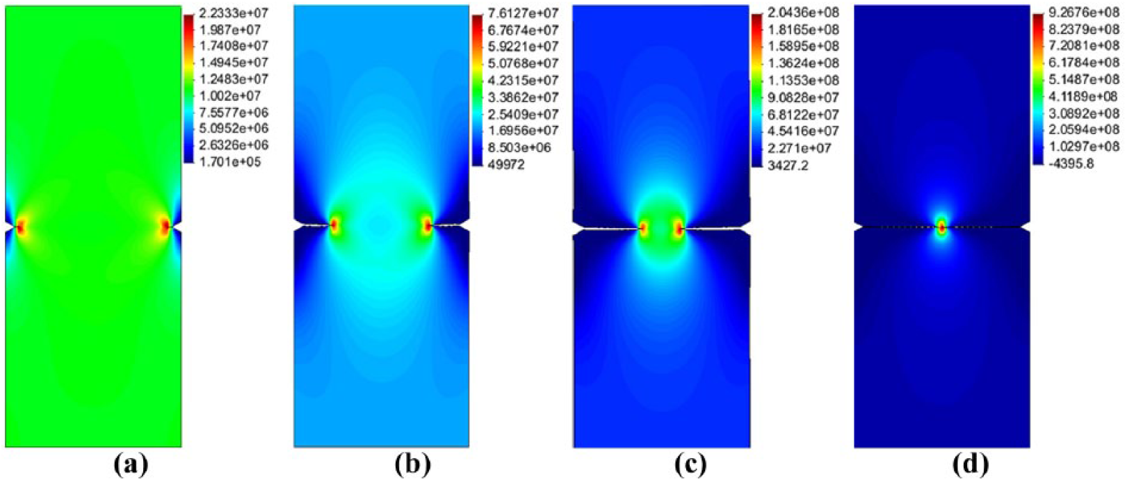
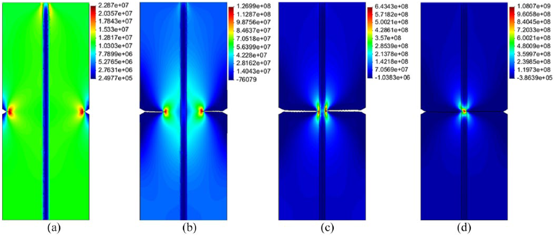
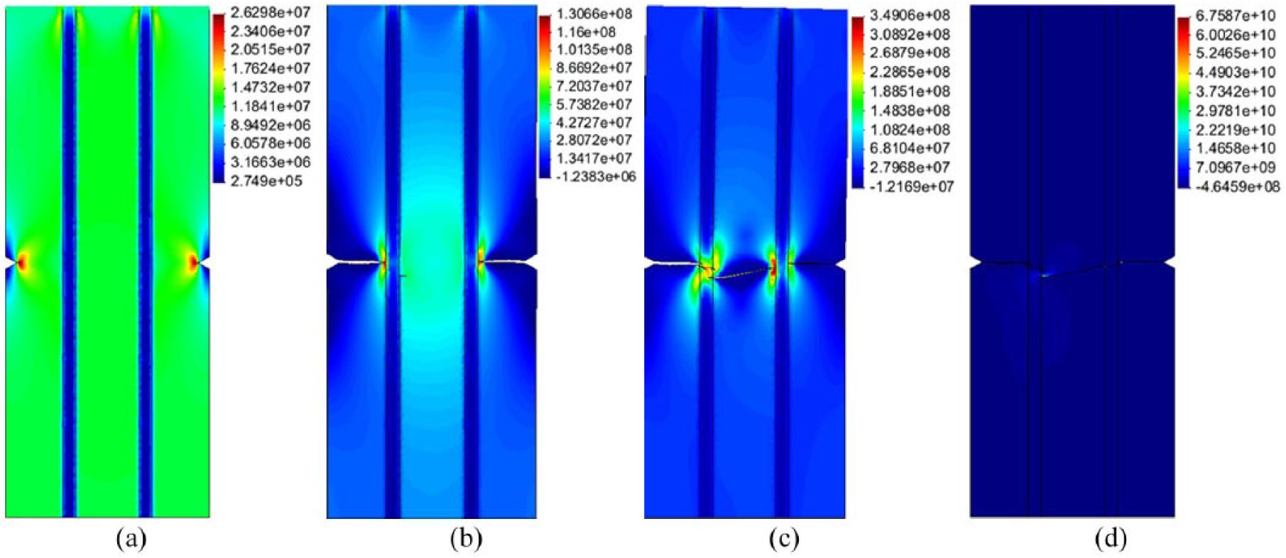
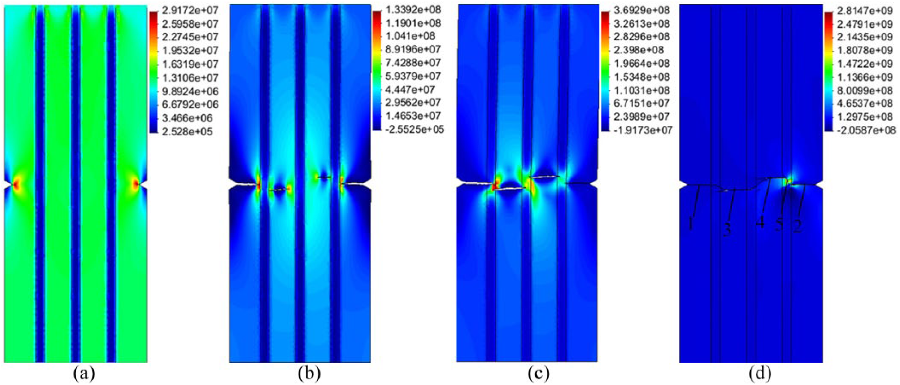
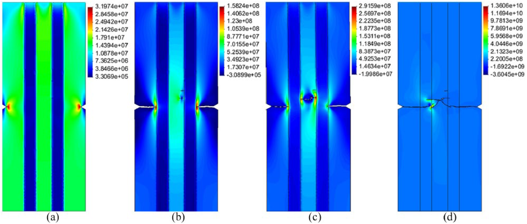
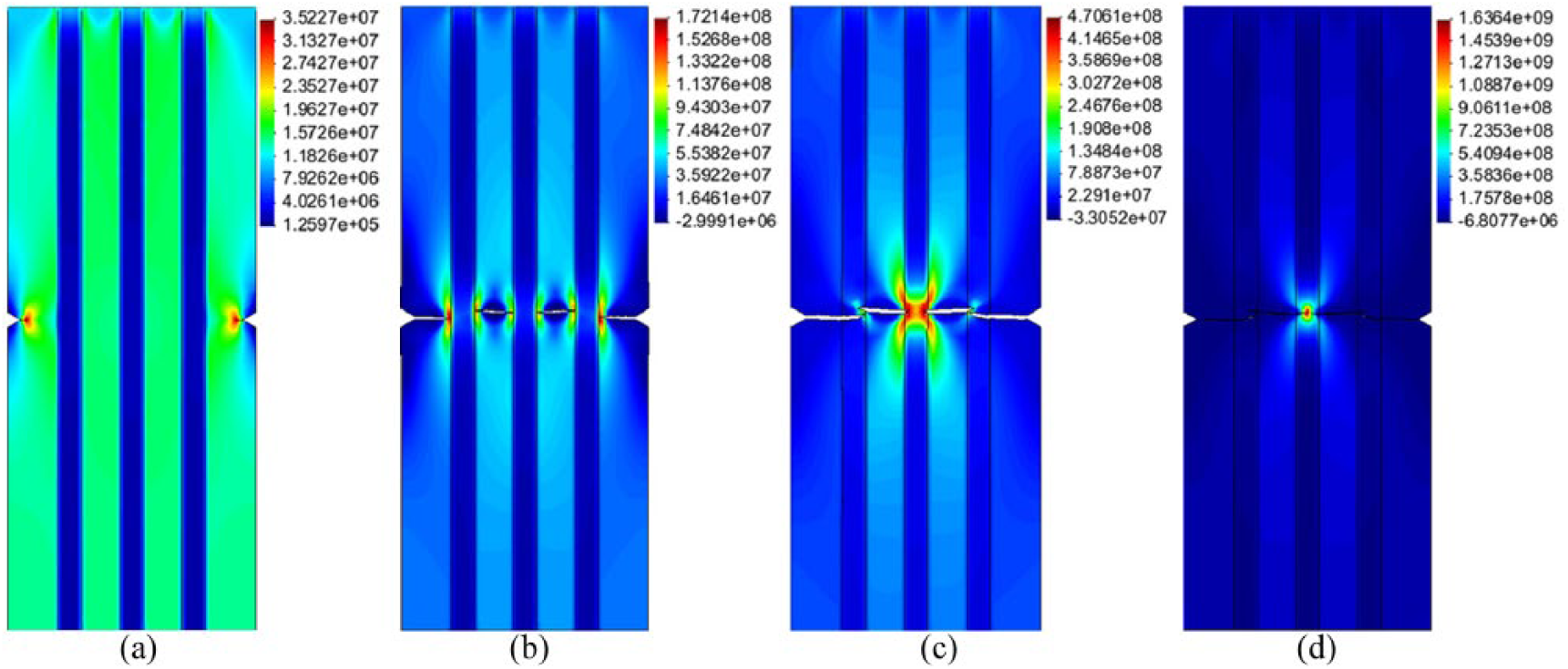
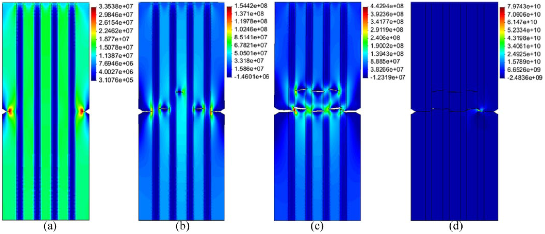
The evolution of major principal stress and crack propagation in the five groups of specimens in Model 1 are shown in Figures 3–7. Influenced by the grooves at the two sides, major principal stress concentrates on the endpoint of the groove. The unit where the major principal stress of certain nodes around the groove satisfies the fracture condition is fragmented and initially cracks, as shown in Figures 3(a) to 7(a), because the matrices are brittle and have low tensile strength. The fracture of the unit releases and transfers the stress of the node and subsequently forms a new stress concentration zone elsewhere. With the continued application of tensile load, the new stress concentration zone will have new nodes whose major principal stress meets the fracture condition; thus, additional units will rupture. The cracks extend to the fibers constantly with this release–transfer–concentration process of the stress of nodes, as shown in Figure 4(b). Fibers are ductile materials with high tensile strength. Thus, inner matrices are damaged earlier than fibers, and the cracks generated inside the inner matrices consistently expand toward the fibers with the transfer of stress of the nodes and the increase in tensile load until the cracks expand toward both sides of the fibers, as shown in Figures 5(b), 6(b), and 7(c). When the cracks in the inner and outer sides of the matrices extend to the sides of the fibers, nodes that meet the fracture condition will appear on the outermost fibers and the fibers break with the fracture of units and the propagation of cracks, as shown in Figures 4(d), 5(c), 6(c), and 7(d). Subsequently, the major principal stress concentration zone moves to the fiber side that is adjacent to the broken fibers, and the fibers in that adjoining side will rupture and fail, as shown in Figures 5(d), 6(d), and 7(e). The specimens are then in an overall fracture state in which all the fibers are broken. This conclusion is consistent with the prediction of Tang and colleagues. 11
Evolution process of the major principal stress of pure matrix specimens.
Evolution process of the major principal stress of one fiber specimen.
Evolution process of the major principal stress of two fiber specimens.
Evolution process of the major principal stress of three fiber specimens.
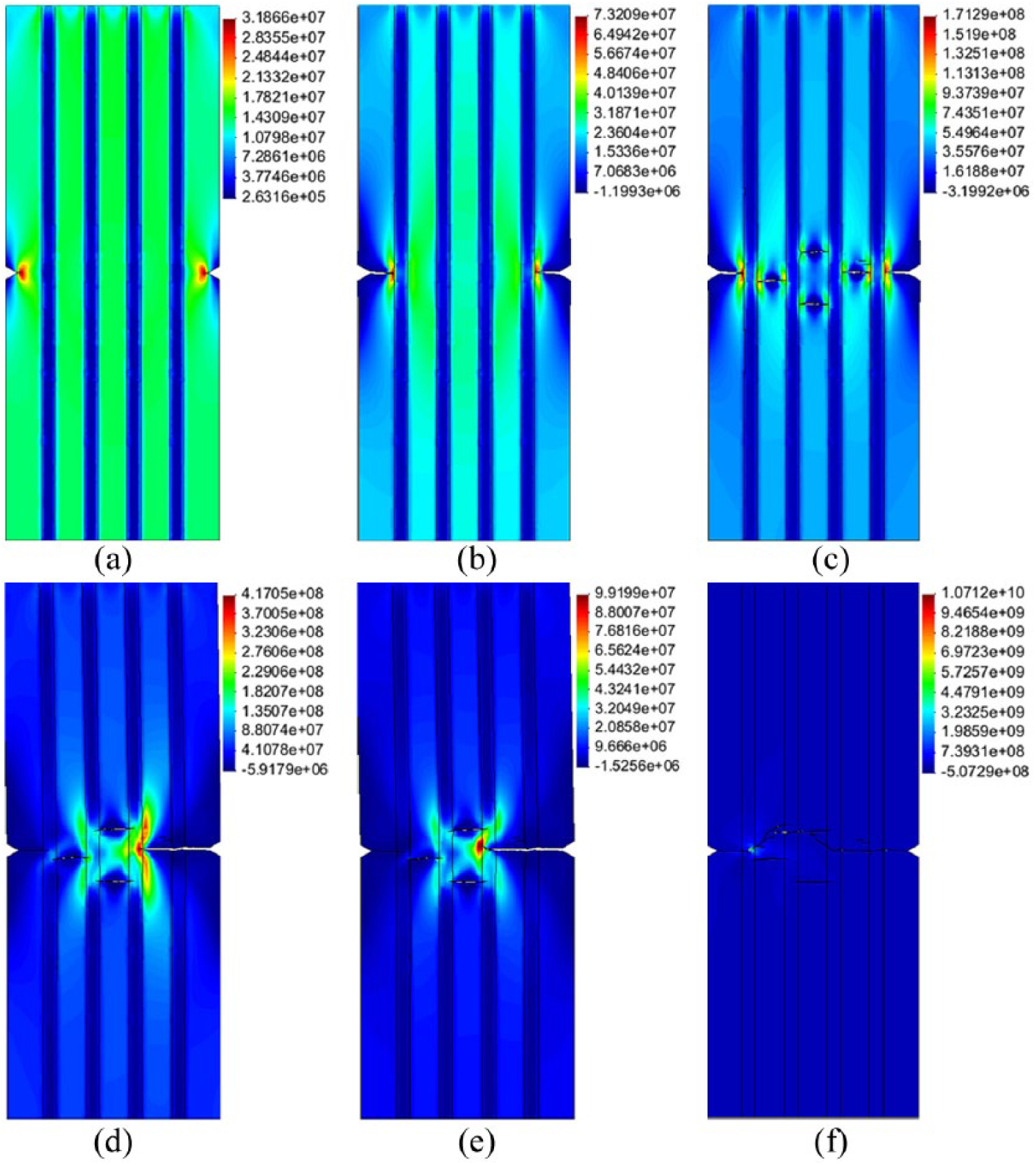
Evolution process of the major principal stress of four fiber specimens.
Figures 3–7 show that with an increase in the number of fibers embedded in the various specimens, the evolution of the major principal stress becomes increasingly complex and the final fracture morphology gradually transforms into multiple complex cracks from single initial cracks.
The laws of major principal stress change for various monitoring points in Figure 6(d) are shown in Figure 8. After initial cracks appear on the endpoint of the groove, the major principal stress concentration zone gradually moves to monitoring points 1 and 2 and the principal stress of these monitoring points progressively increase. With the fracture of the unit in which monitoring points 1 and 2 are located, the principal stress of the monitoring points decreases and eventually approaches zero. Similar to monitoring points 1 and 2, the principal stress of monitoring points 3 and 4 increase gradually as the major principal stress concentration zone moves to the inner matrix; subsequently, the principal stress decreases and approaches zero. Monitoring point 5 is inside the right fiber, and its principal stress increases sharply as the major principal stress concentration zone moves to monitoring point 5. Thereafter, the unit in which monitoring point 5 is located ruptures, and principal stress decreases and approaches zero.
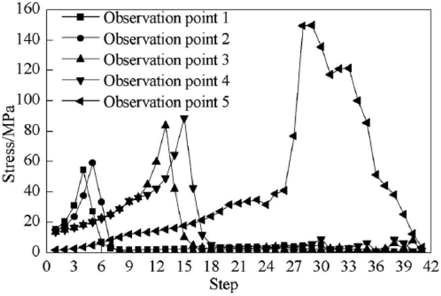
Laws of major principal stress change for monitoring points.
Analysis of tensile properties
The relationship between the tensile strength and number of fibers in the five groups of specimens in Model 1 is shown in Figure 9. The tensile strength of the pure matrix specimens is the lowest among all specimens. After the fiber is embedded in the matrix, the tensile strength of the fiber becomes higher than that of the matrix. The propagation of the crack in the specimen is hindered by the fiber, thereby increasing the tensile strength of the specimen. This result is consistent with the analysis by Tang and colleagues. 11 With an increase in the number of fibers in the matrix, the crack propagation path becomes longer and the tensile strength of the specimens increases. The tensile strength of the specimens that are embedded with four fibers is double that of the pure matrices.
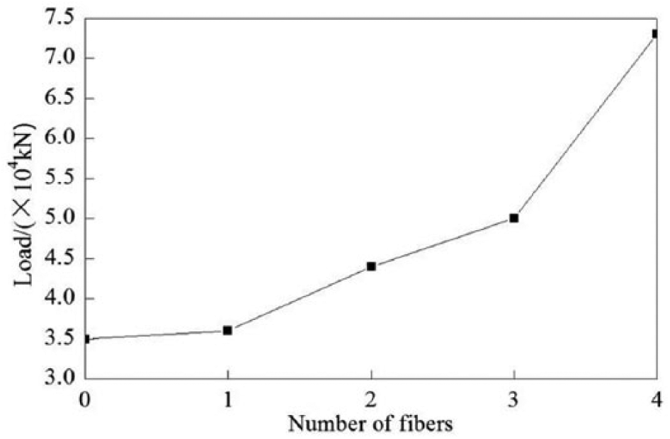
Relationship curve for tensile strength and fiber number of various specimens in model 1.
Results of numerical simulation of Model 2 and corresponding analyses
Evolution of major principal stress and crack propagation
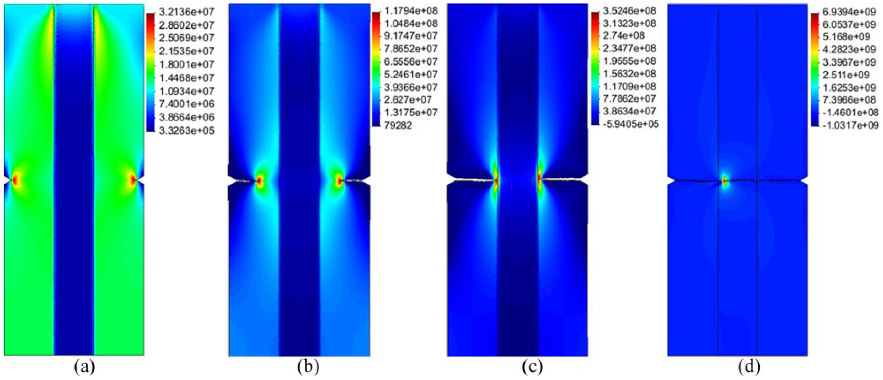
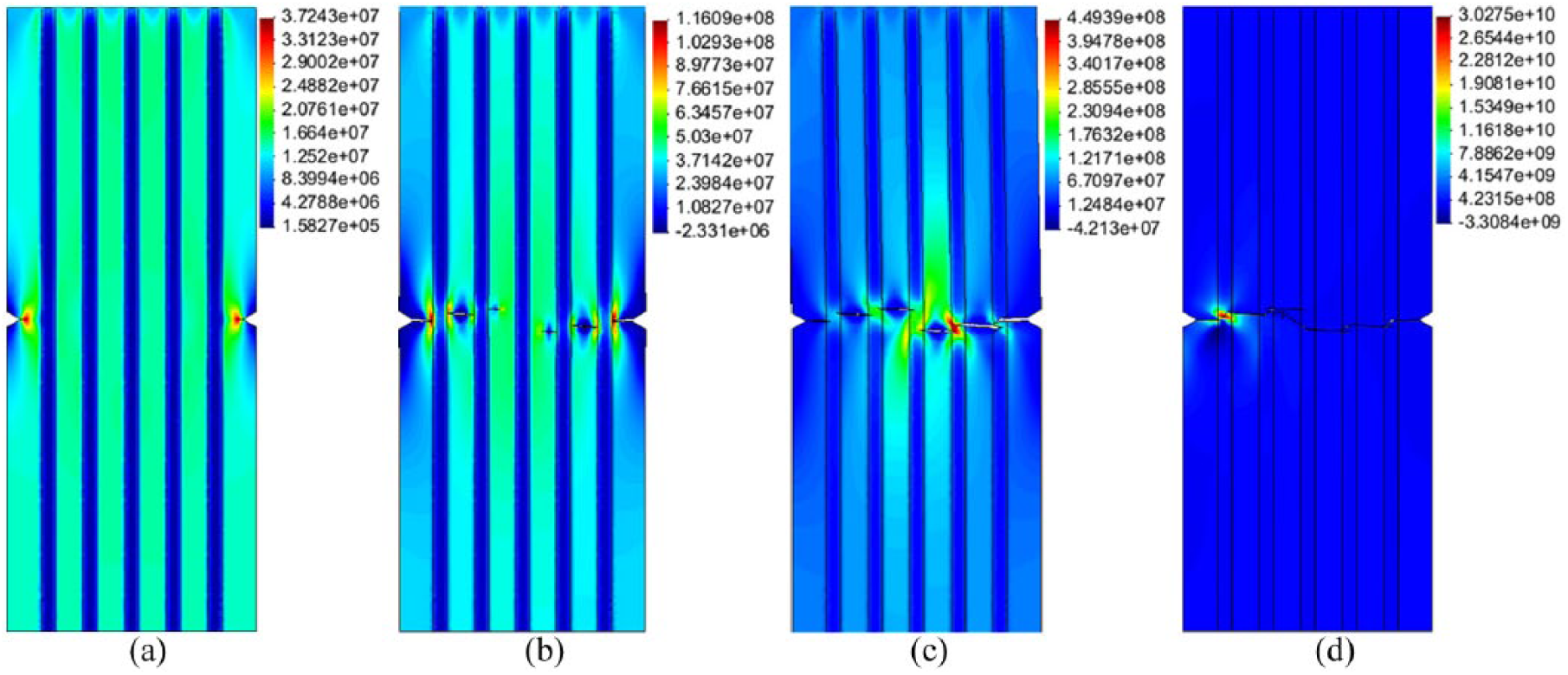
The evolution of major principal stress and crack propagation inside the five groups of specimens in Model 2 are shown in Figures 10–14. Initial cracks appear on the endpoints of the groove of the outer matrices, as shown in Figures 10(a) to 14(a). With the constant increase in tensile load, the initial cracks propagate to the side of the fibers in the release–transfer–concentration process of stress of the nodes, as shown in Figures 10(c), 11(c), and 12(b). When nodes that meet fracture conditions appear in the fiber, the fiber breaks, as shown in Figures 10(d), 11(d), and 12(c) to 14(c). The major principal stress concentration zone thereafter moves to the adjacent fiber, thus resulting in the fracture of the latter, as shown in Figures 12(d) to 14(d). When the last fiber inside the specimen breaks, the specimen is in an overall fracture state.
Evolution process of the major principal stress of specimens with one fiber.
Evolution process of the major principal stress of specimens with two fibers.
Evolution process of the major principal stress of specimens with three fibers.
Evolution process of the major principal stress of specimens with four fibers.
Evolution process of the major principal stress of specimens with five fibers.
Analysis of tensile properties
The relationship between tensile strength and number of fibers in the five groups of specimens in Model 2 is shown in Figure 15. The tensile strength of the specimen increases gradually with the number of fibers embedded in it. Decreased fiber width and increased number of specimens strengthen the effect of crack propagation in the specimen and improve the tensile strength of the specimen. The tensile strength of the specimen with five fibers is nearly double that of the specimen with only one fiber.
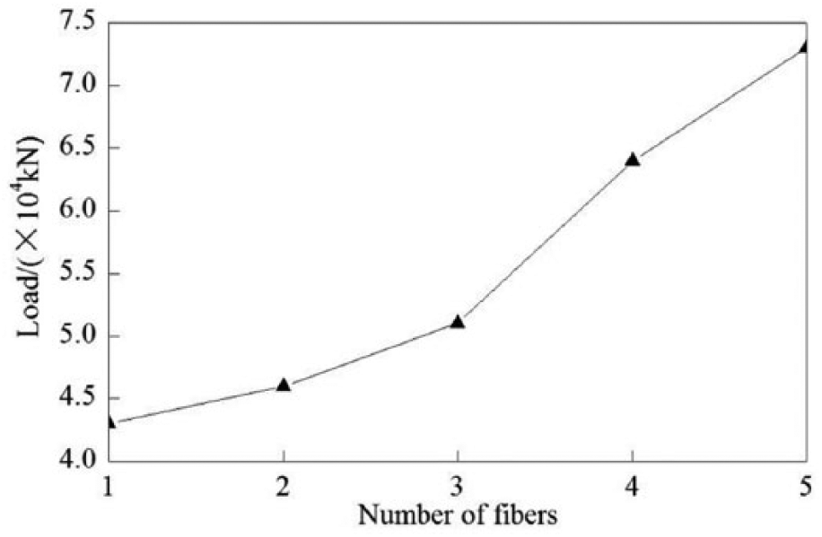
Relationship curve for tensile strength and fiber number of various specimens in model 2.
Conclusion
A tensile failure finite element model based on fracture mechanics was built for fiber composites. The evolution of the major principal stress and the crack propagation inside the specimen were investigated under situations in which the width of a single fiber and the total width of the fibers were unchanged. The effect of the number of fibers on the failure process and strength of the composites was also analyzed. The following are the main conclusions:
Under uniaxial tensile action, the final fracture morphology of the pure matrix specimens shows a single crack and exhibits brittle fracture. After embedding fibers into the matrix, the fracture morphology of the composite specimen shows twists and turns upon breakage and the brittleness of the materials decreases.
When the width of a single fiber and the total width of the fibers inside the composite specimen are certain, the evolution of the major principal stress and the crack propagation in the specimen increase in complexity with the number of fibers embedded into the matrix. The tensile strength of the specimen thereby increases.
Footnotes
Acknowledgements
The authors would like to thank the National Natural Science Foundation of P. R. China (Grant Nos. 41372301 and 41641027), the Foundation of Si’chuan Educational Committee (Grant No. 15ZB0124), and the Longshan Academic Talent Research Support Program of the Southwest University of Science and Technology (Grant No. 17LZX421) for their financial support for this study.
Declaration of Conflicting Interest
The author(s) declared no potential conflicts of interest with respect to the research, authorship, and/or publication of this article.
Funding
The author(s) disclosed receipt of the following financial support for the research, authorship, and/or publication of this article: This research received no specific grant from any funding agency in the public, commercial, or not-for-profit sectors.