
Abstract
Introduction:
Smart structures equipped with piezoelectric devices to sense and actuate the structure could be used in many engineering applications. To explore the smart structure further and apply it to more complex structures, some problems are critical to be concerned. Among them, delamination due to the high stress is an important issue since its serious effect on the strength and stiffness of the composite structure.
Method:
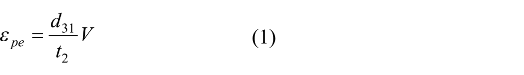
In this investigation, a piezoelectric layer is embedded into the host structure to form a sandwich composite structure. The piezoelectric layer is subjected to an electric voltage, yielding the bending effect on the sandwich composite structure. A theoretical model based on the Euler beam theory and interfacial continuity is presented to determine the stresses of the sandwich composite beam caused by the piezoelectric layer.
Results:
The influences of the embedded depth and Young’s modulus of the piezoelectric layer on the stress distribution of the sandwich composite beam are investigated through a parametric study. The analytical solutions are verified by the finite element method. Good agreement is achieved between the present approach and the finite element method.
Conclusions:
Numerical analysis indicates that the maximum tensile stresses in the top and bottom layers are decreasing with the increase of the embedded depth, while the maximum compressive stress in the lead zirconate titanate layer is increasing with the increase of the embedded depth. Both the top and bottom layers are subjected to tensile stress and increasing with the increase of the Young’s modulus ratio, while the piezoelectric layer is subjected to compressive stress and increasing with the increase of the Young’s modulus ratio.
Introduction
Piezoelectric composite structures made from lead zirconate titanate (PZT) have been widely used in adaptive structures and smart devices. 1 Adaptive structures incorporating an embedded or surface-bonded piezoelectric layer have provided a variety of applications, such as active vibration control, shape control, and noise suppression. 2 Smart structures consisting of sensors and actuators coupled by a controller have the capability to respond to the environmental change and control the structural movement. A piezoelectric material is one of the most widely used distributed sensor and actuator in smart structures. Many researchers have proposed the modeling of piezoelectric materials either embedded or surface bonded to different types of structures. Abdeljaber et al. utilized a new intelligent methodology based on the neural network control algorithm for active control of flexible cantilever plates using piezoelectric sensor/actuator pairs. 2 Rabinovitch employed piezoelectric materials for the control of the edge stresses and the edge debonding failure in reinforced concrete beams. 3 Kapuria and Dhanesh investigated the free edge stresses in hybrid composite panels integrated with piezoelectric transducer layers based on the Reissner-type mixed variational principle. 4 Their solutions successfully captured singular nature of free edge interlaminar stresses under different loadings such as extension, bending and twisting loads. Xiang and Shi determined the stress distribution and deflection of multi-layered piezoelectric cantilevers using the Airy stress function method. 5 The effects of both the bonding layers and electrodes were taken into account. Selim et al. investigated the free vibration analysis as well as the active vibration control of functionally graded material (FGM) plates with piezoelectric layers using Reddy’s higher-order shear deformation theory in association with the element-free IMLS-Ritz method. 6 Tinoco et al. employed piezoelectric transducers to detect the damage in plate using the electromechanical impedance technique. 7 Karayannis et al. presented an experimental method for the damage assessment of concrete reinforcing bars using bonded piezoelectric transducers based on the electromechanical admittance method. 8
Smart structures equipped with piezoelectric devices to sense and actuate the structure could be used in many engineering applications. Most of the researches have devoted to the vibration suppression and shape control of active structures incorporating piezoelectric actuators. To explore the smart structure further and apply it to more complex structures, some problems are critical to be concerned. Among them, delamination is an important issue due to its serious effect on the strength and stiffness of the composite structure. Delamination is caused by the high interlaminar stresses at the interface of composite layers. Artel and Becker studied the effect of piezoelectric coupling on interlaminar stresses and electric field near the free edge using the finite element method. 9 Izadi and Tahani derived an analytical solution to determine the interlaminar stresses of general cross-ply laminates with piezoelectric layers as actuators under transverse mechanical loads basing on the second-order shear deformation plate theory. 10 Yang et al. investigated the interlayer stresses in laminated beams consisting of piezoelectric and elastic layers using three-dimensional finite element method. 1 Piezoelectric materials usually behaviour brittle failure, fracture analysis is important for their reliability and effective serves. Alibeigloo and Madoliat employed differential quadrature method and Fourier series to determine the stress, displacement and electric potential distributions of a cross-ply rectangular plate induced by embedded piezoelectric layers. 11 Cheng and Li used the Levy solution and state-space method to evaluate the stresses of a composite joint integrated with PZT layers subjected to torsion. 12 Mannini and Gaudenzi investigated stress concentration at free edge of a piezoelectric composite laminate. 13 Maurini et al. proposed a mixed variational formulation to establish a Euler–Bernoulli model of layered piezoelectric beams and piezoelectric laminates where the effects of transverse stresses and strains were taken into account.14,15 Sandwich composites with light weight and high strength are widely employed in automotive, nuclear, and aerospace industries. However, the sudden change in material properties across the interface can result in debonding, which is a major problem in sandwich construction. To increase the resistance of sandwich plates to this type of failure, the concept of a FGM is being actively explored in sandwich composite design. 16 Khalfi et al. studied the thermal buckling of solar functionally graded plate using a refined and simple shear deformation theory. 17 Belabed et al. presented a simple higher order shear and normal deformation theory for composite plates. 18 Larbi et al. proposed an efficient shear deformation beam theory based on neutral surface position for bending and free vibration analyses of functionally graded beams. 19 Nguyen et al. derived a closed form solution for the transversely functionally graded tapered beam based on the Euler–Bernoulli beam theory and the principle of virtual work. 20
It is well known that the stress concentration usually occurs near the free edge of a multi-layered structure. The stress level and concentration depend heavily on the geometrical parameters and material properties of the multi-layered structure. The objective of this study is to present a theoretical model to evaluate the stresses in composite structure induced by the embedded PZT layer. An analytical solution of the stress distribution across the thickness of the sandwich composite structure caused by the embedded PZT layer is derived based on the Euler beam theory and compatibility condition at the interfaces. The stresses are expressed in terms of the material properties and thickness of the sandwich composite beam. The influences of the embedded depth and Young’s modulus of the piezoelectric layer are investigated through a parametric study.
Stress analysis
Three layers with thicknesses of
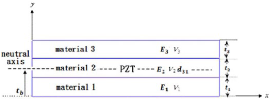
Sandwich composite beam.
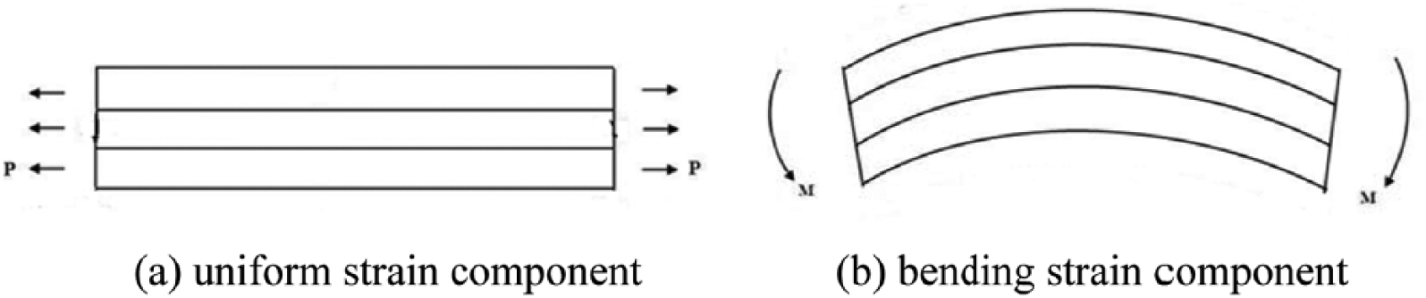
In this study, the sandwich composite beam consists of three layers which are bonded to each other, leading to a continue strain across the interface. With the same interfacial strain and different elastic moduli, a discontinuity of interfacial stress will occur at the interface. Utilization the Euler beam theory and strain continuity at the interface between adjacent layers, the total strain of the sandwich composite beam can be expressed as the summation of two components, namely, uniform strain and bending strain (as shown in Figure 2):
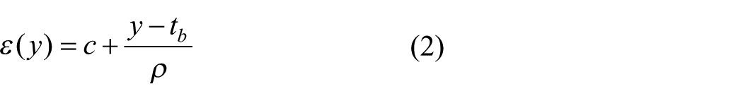
where
Strain in the sandwich composite beam.
Utilizing the stress–strain relationship, the stress distribution along the thickness of each layer in the sandwich composite beam can be expressed as
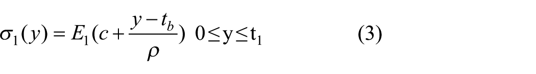
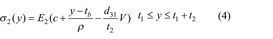
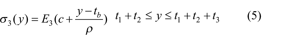
There are three undetermined constants,
The summation of the forces exerted on each layer of the sandwich composite beam due to the uniform strain is equal to zero:
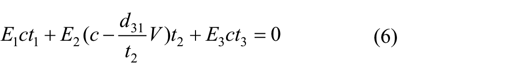
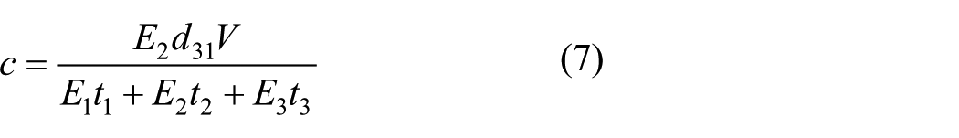
The uniform strain component is readily determined from equation (6):
The summation of the forces on each layer of the sandwich composite beam due to the bending strain component is equal to zero:
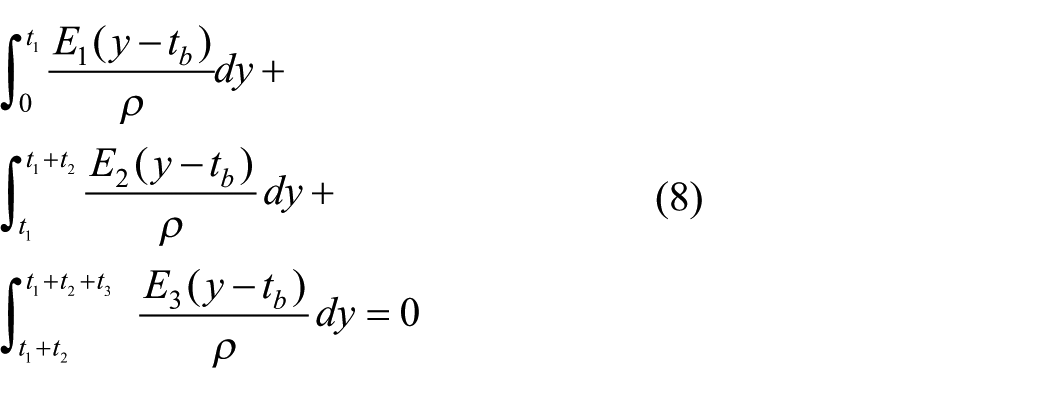
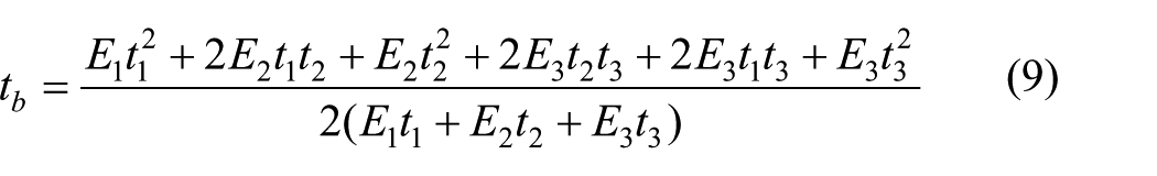
The position of the neutral axis for the sandwich composite beam can be obtained from equation (8):
The summation of the bending moments on each layer with respect to the neutral axis
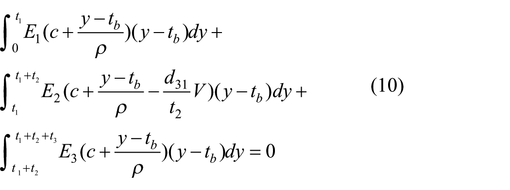
The radius of the curvature of the sandwich composite beam can be calculated from equation (10):
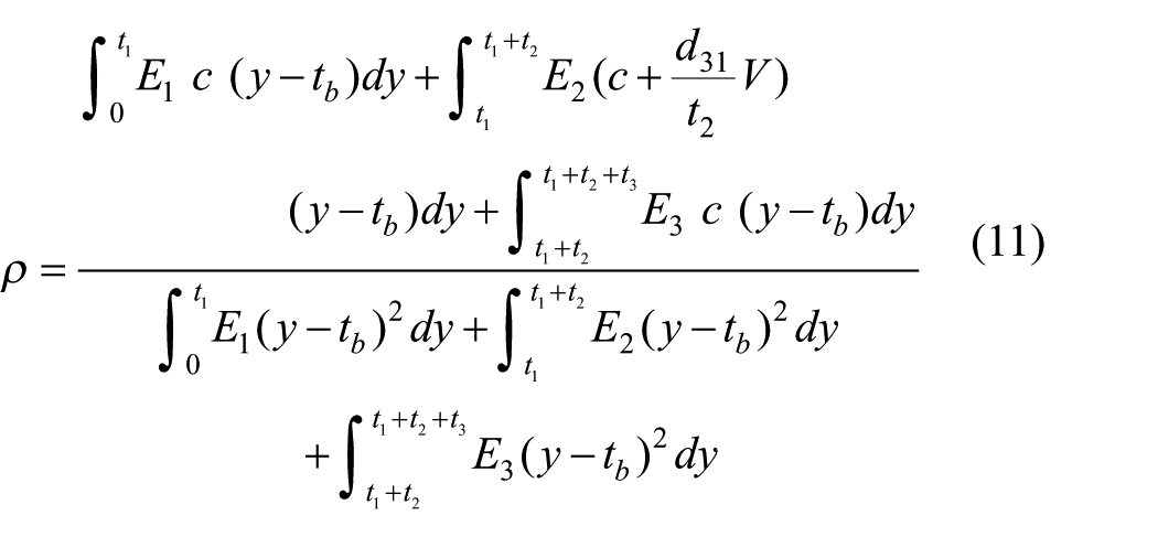
Thus, substituting equations (7), (9), and (11) into equations (3)–(5) leads to the determination of the stresses in each layer of the sandwich composite beam as a result of an electric voltage V applied to the PZT layer.
Finite element verification
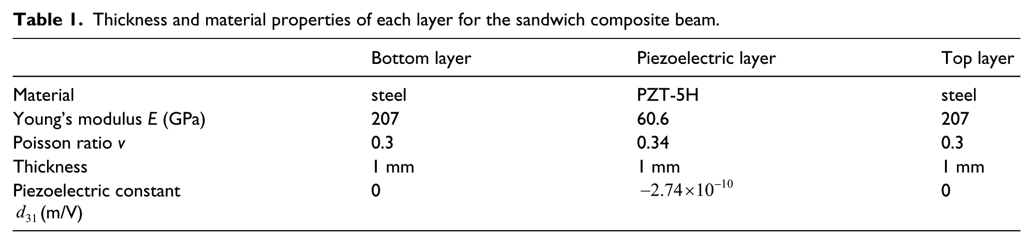
In the previous stress analysis, the stress and strain distributions across the thickness of the sandwich composite beam caused by the PZT layer are derived using the piezo-elasticity theory and Euler beam theory. To validate the theoretical prediction, a numerical analysis using the finite element method is conducted. The finite element analysis was employed under the plane stress condition using the commercial software ANSYS. The two-dimensional (2D) element PLANE 13, which can be used for the piezoelectric material, was adopted, while PLANE 42 was used for the layers on the top and bottom. PLANE 13 has 2D thermal, electrical, piezoelectric, and structural field capabilities with coupling between the fields. The degrees of freedom of the PLANE 13 are the horizontal and vertical displacements and electrical potential (voltage). PLANE 42 is used for 2D structures with four nodes having two degrees of freedom at each node: translations in the nodal x and y directions. Figure 3 shows the finite element mesh. The materials used in this study are steel and PZT-5H. The thickness and material properties of each layer for the sandwich composite beam are presented in Table 1. The length of the sandwich composite beam is 20 mm. The sandwich composite beam is subjected to an electric loading of 100 V on the piezoelectric layer. The boundary conditions are free and the interfaces between two adjacent layers are assumed to be perfectly bonded.
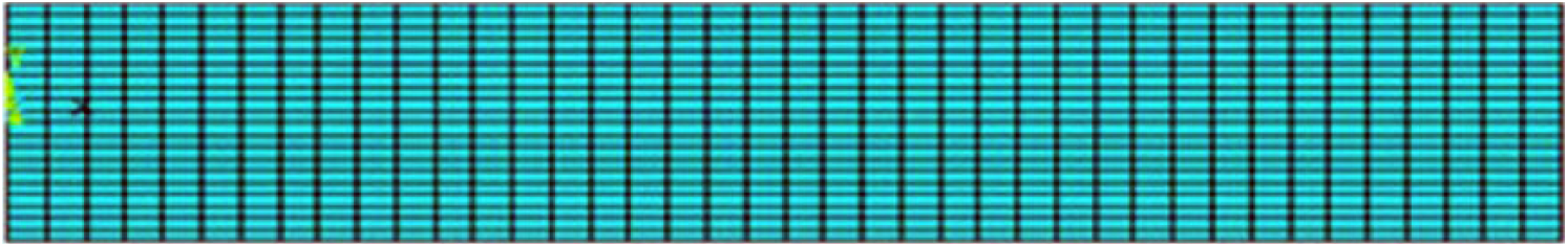
Finite element mesh.
Thickness and material properties of each layer for the sandwich composite beam.
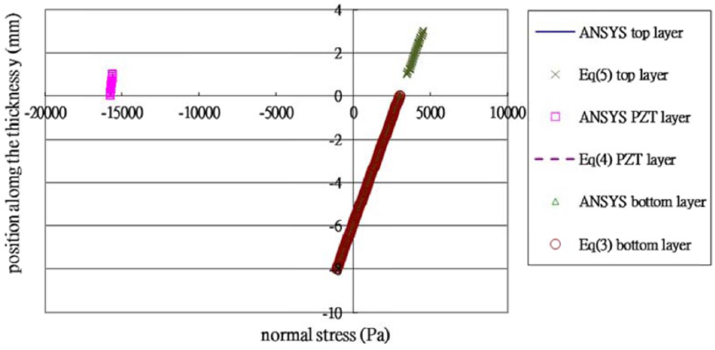
The theoretical prediction of the stress distribution along the thickness of the sandwich beam using equations (3)–(5) is compared with the finite element result at the middle location in length, as shown in Figure 4. It appears that the stress distribution obtained by the analytical solutions and numerical results from the finite element method is almost the same. The difference between the theoretical prediction and finite element method is less than 1%, which illustrates the good accuracy of the present approach. Numerical results indicate that the normal stress in each layer is constant across the thickness. The bending strain component is zero since the sandwich beam is symmetric with respect to the piezoelectric layer. Piezoelectric layer is subjected to compressive stress while the top and bottom layers are in a state of tensile stress. In the next verification example, the thicknesses of the top, PZT, and bottom layers are changed to 2 mm, 1 mm, and 8 mm, respectively. The stress distribution along the thickness is plotted in Figure 5. Linear stress distribution along the thickness shows the bending effect due to the unsymmetrical thickness. The stress distribution obtained by the theoretical prediction and finite element method is in a close agreement.
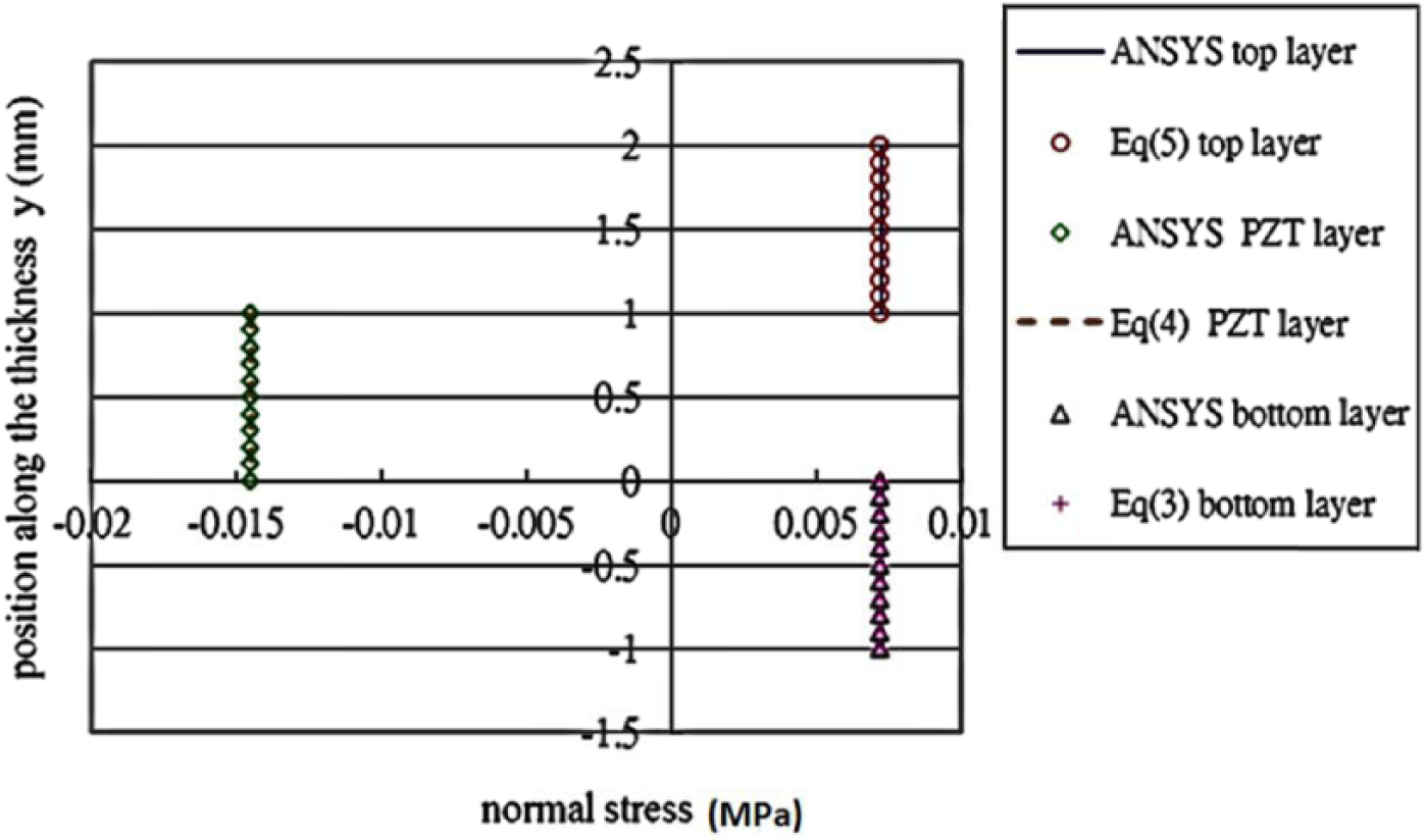
Stress distribution across the thickness of the sandwich composite beam with the same thicknesses of each layer.
Stress distribution across the thickness of the sandwich composite beam with different thicknesses of each layer.
Parametric study and discussion
The analytical solution of the stresses in the sandwich composite beam has been validated by the finite element method. The aim of the parametric study is to investigate the influences of the embedded depth of the piezoelectric layer and the elastic modulus of the sandwich composite beam on the stress distribution.
Example 1: influence of the embedded depth
The same materials as listed in Table 1 for the sandwich composite beam are used in this example. The influence of the embedded depth of the PZT layer in the sandwich composite beam is examined. The total thickness of the sandwich composite beam and the thickness of the piezoelectric layer are fixed with 11 mm and 1 mm, respectively. The depth d of the embedded piezoelectric layer measured from the top surface of the sandwich beam is equal to the thickness of the top layer, i.e.
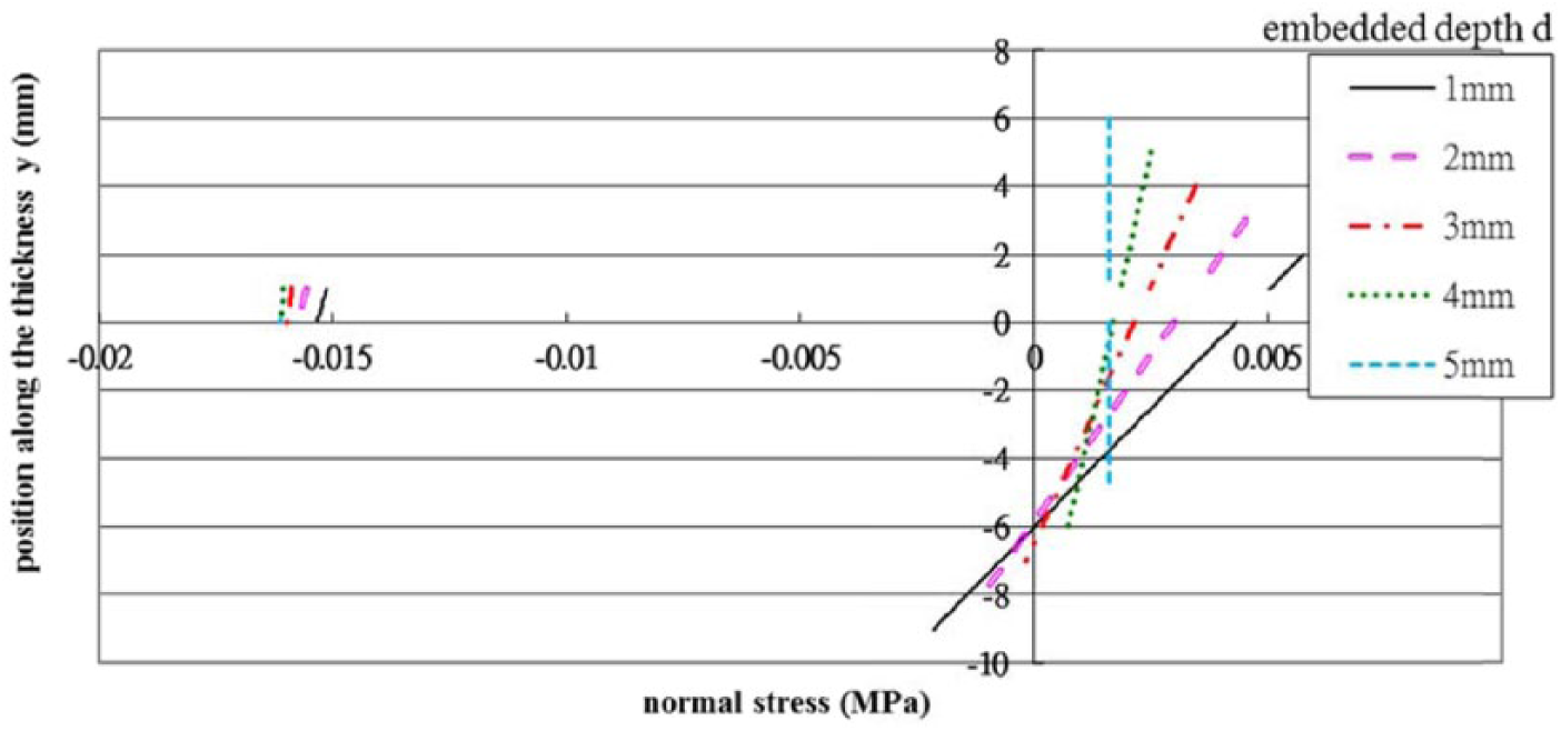
Stress distribution across the thickness of the sandwich composite beam with piezoelectric layer embedded in various depths.
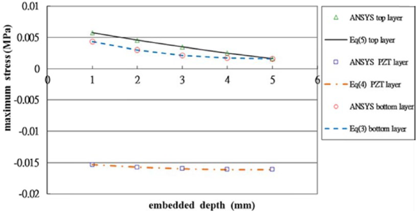
Maximum tensile stresses in the top and bottom layers and maximum compressive stress in the PZT layer for various embedded depths.
Example 2: influence of the Young’s modulus
The PZT material is the same as previous example while the top and bottom layers are varied. In this example, the materials for the top and bottom layers are the same with Young’s modulus varied from 6.06 to 606 GPa, resulting in the Young’s modulus ratio (
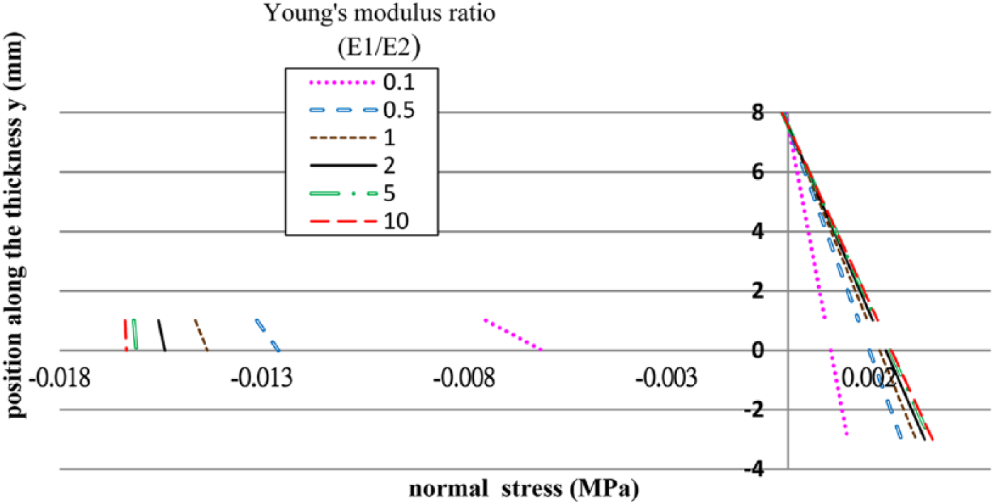
Stress distribution across the thickness of the sandwich composite beam with a variety of Young’s modulus ratios
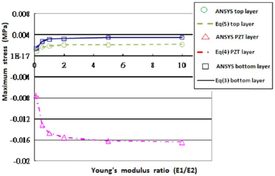
Maximum tensile stresses in the top and bottom layers and maximum compressive stress in the PZT layer for a variety of Young’s modulus ratios
The feasibility of the proposed model in the determination of the stress of the composites structure induced by the embedded PZT layer is demonstrated through a parametric study. The effect of the embedded depth and material property on the stress distribution of the composite structure is presented.
Conclusions
Stresses in the sandwich composite system are important since they can significantly affect the reliability and strength of the sandwich composite structure. To investigate the stress distribution in the composite structure induced by the embedded PZT layer, the compatibility condition at the interface between the adjacent layers is employed. In this study, the strain in the sandwich composite beam is expressed as the sum of a uniform strain component and a bending strain component. An analytical solution of the stresses in terms of the thickness and Young’s moduli of the sandwich composite structure is derived. The theoretical prediction was validated by the finite element method. Good agreement between the present approach and finite element method is achieved. The influences of the embedded depth and elastic modulus of the piezoelectric layer on the stress distribution are investigated through a parametric study. It can be observed that the maximum tensile stresses in the top and bottom layers are decreasing with the increase of the embedded depth, while the maximum compressive stress in the PZT layer is increasing with the increase of the embedded depth. Both the top and bottom layers are subjected to tensile stress and increasing with the increase of the Young’s modulus ratio
Footnotes
Declaration of Conflicting Interests
The author(s) declared no potential conflicts of interest with respect to the research, authorship, and/or publication of this article.
Funding
The author(s) disclosed receipt of the following financial support for the research, authorship, and/or publication of this article: This work was supported by the Ministry of Science and Technology of the ROC (grant number MOST 104-2221-E155-057-MY3).