



Abstract

Introduction
As pharmaceutical research continues the drive to screen higher numbers (HTS), economics dictate the use of smaller quantities of precious compounds and expensive reagents per assay. Researchers are meeting this requirement with new assay developments. This impacts the use of liquid handling instrumentation, to meet the dimensional requirements of the higher density formats while maintaining the precision the industry has come to expect.
There are two types of liquid dispensing methods in use today - piston displacement and ink jet technology. Piston displacement has been the workhorse of the industry. Simply, a piston moving in a close fitting cylindrical space that is sealed at one end and open at the other. It is exemplified by the myriad of hand held and automated pipettors that are currently on the market, in a variety of forms.
Ink jet technology derives its name from its early adaptation in the printing industry. Ink jet technology uses some means of creating pressure in a liquid against a small orifice. As the orifice opens, the back pressure imparts sufficient linear velocity to the liquid to eject it, in a fast moving stream. However, by closing the orifice quickly the stream can become an ejected drop. The size of the drop is primarily controlled by the orifice size, back pressure and length of time the orifice is open. An informative article on ink jet dispensing by Don Rose appeared in LAN (Vol. 2 No. 4, Sept 1997).
With piston displacement, if the piston moves fast enough against a small outlet orifice, it also will deliver as a stream. The normal method of delivery however, controls the piston movement so as to measure a specific amount. As a result, there is usually insufficient stream velocity to overcome the effects of surface tension and the associated capillary action at the dispensing tip orifice. These parameters become a greater factor in small volume liquid handling. In general terms, piston displacement becomes limited in the sub-microliter range of delivery. With current technology it is difficult to achieve the accepted limits of precision below 0.2 to 0.5 microliters (200 to 500 nanoliters). Even at these limits special precautions are required.
Accuracy vs. Precision
Accuracy in pipetting is defined as the relationship between the volume that is set and the volume that is actually delivered. If the dial or display is set at 100 microliters and 98 microliters is actually delivered, the pipettor has an accuracy of 98% or a 2% error. Precision is a measure of repeatability. It is expressed as a non-dimensional coefficient of variation (Cv). The Cv is the standard deviation of a number of events (dispenses) divided by the mean value of those events. In biological assays, it is a greater concern that multiple samples are handled alike. Thus, precision normally has a higher priority than accuracy.
Air Displacement vs. Positive Displacement Pipetting
Air displacement is the most common method of pipetting liquids. A piston is moved within its' cylindrical housing, displacing a volume of air. This creates a vacuum in the pipette tip, causing liquid to move into the tip to displace the vacuum that was created. There is always a dead air cushion between the piston and the liquid in the tip.
In a positive displacement pipettor there is no compressible air cushion between the piston and the liquid in the pipette tip. Normally the piston goes to the bottom of the tip and is in contact with the liquid in the tip that is being pipetted. Contaminating the end of the piston, with the liquid being pipetted, is not desirable in most cases. An alternative is to back fill, what would be the air space between the piston and the end of the pipette tip, with a non compressible fluid such as water. Then a slight airgap is drawn to separate this backfill liquid and the liquid being pipetted. This is commonly done with syringe pump pipettors. The Quadra96®, a multiple 96 well pipettor, can also operate in this backfilled mode.
Air displacement pipetting, while easier to accomplish, does not have the accuracy or precision, particularly at small volumes, that is available with positive displacement pipettors. This is due to the compressibility of the dead air column in the pipettor. The explanation is as follows:
1 - Starting Conditions 2 - Aspirate 250μl
Assume a manual 250μl air displacement pipettor is used with a 250μl pipette tip. The dead air volume will be a function of the mechanical design plus the maximum volume of the tip being used.
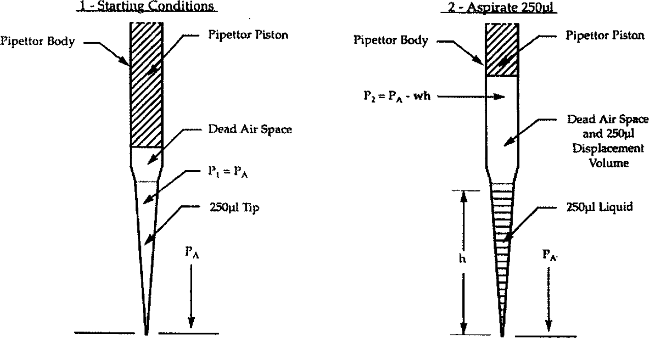
At the start, the air pressure in the tip was atmospheric (i.e. PI = PA). As the piston moves up into the body of the pipette it displaces air, creating a negative pressure in the tip. The liquid flows into the tip orifice due to atmospheric pressure acting on the liquid reservoir. At condition #2, in the ideal condition, the air pressure in the tip would be equal to atmospheric PA and V1 would equal V2.
This is defined by the ideal gas law PV = RT. Since it is the same gas (air) at the same temperature (T1 = T2) then PIV1 =P2V2.
However, the column of liquid has a pressure head, defined as wh (w = specific gravity of the liquid and h = the column height). At the tip orifice the pressure is atmospheric. If the liquid is to remain in the tip then this pressure at the orifice must be offset by a negative pressure (vacuum), within the closed or dead air portion of the tip. Thus, P2 must be less than PA by the value of wh.

Thus, V2 the displaced volume must be greater than the original volume V1 by the factor wh. In other words, the pipettor piston must move back not only the desired volume of 250μl (V1) but an additional volume to create enough vacuum to offset the pressure head in the tip. To put it in actual terms assume water is being pipetted.
VI = Dead Air Volume in Pipettor Body and Tip Volume, assume 500μl
Atmospheric Pressure = 406.8 inches H2O
Assume the water in the tip = 2.0 inches
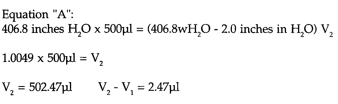
Thus, the piston had to displace an additional 2.47μl to aspirate and hold the 250μl sample, or 1% accuracy error.
The equation at ‘A’ also demonstrates the effect of the volume of dead air. If the 500μl figure is reduced to 250μl then the difference between V2 and V1 is cut in half. If taken to the limit (i.e. no dead air), then V2 =V1 which is the case in positive displacement pipettors. This equation has been simplified to demonstrate the relationship of dead air volume and liquid level in the tip. It ignores other factors such as surface tension and its associated capillary action at the tip orifice. These factors must also be overcome by a related increase or decrease in pressure, within the pipettors enclosed space, and its associated volume change.
In small volume pipetting, the inside diameter of the tip orifice must be reduced. The proximity of the inner walls of the tip increases the surface tension forces at the orifice. These additional forces must be overcome both on the aspirate (flow in) and dispense (flow out) function. On the aspirate function the surface tension forces tend to impede flow in. Thus the speed of the aspirating piston may have to be slower with a small orifice and particularly if the liquid has any viscosity (i.e. a 1% solution of BSA will not flow as fast as water).
On the dispense stroke it is beneficial to have some amount of blow out air following the sample. Even then, surface tension will still hold some amount at the tip orifice. A drop of 0.1 microliters is insignificant when pipetting 100μl or even 10μl, but at 0.5 microliters it represents 20% of the sample volume.
Suggested Practices for Small Volume Pipetting
Positive displacement pipettors can provide better precision at small volumes than air displacement. This can be accomplished with backfilled systems or with pipettors that bring the piston in close proximity to the tip orifice. The later poses the problem of piston contamination between samples. Unless the piston is to be replaced each time, some method of washing the tip and piston is required.
The use of Teflon® coatings has become an accepted method of making tip surfaces hydrophobic (repel water). Augmenting these coatings with tip washing methods, such as the use of ultrasonics, provides a solution. The action of the ultrasonics agitates the tip and piston surface at a high frequency, which in effect breaks down the surface tension forces. There is a tradeoff concerning the use of ultrasonics. An ultrasonic bath has a transducer attached to the metal container of the bath which causes it to vibrate at ultrasonic frequencies. This vibration is transmitted to the tips by means of the water in the bath. If the water has entrained air the efficiency of this transfer is diminished. The ultrasonic action will remove entrained air. While it is desirable to have fresh water in the bath it is more efficient to gradually change it, thus reaching a compromise between deaerated water and clean water.
A small pipette tip orifice is required, on the order of 0.015 inch diameter. This presents a problem with respect to particulate matter. Of equal importance the small orifice must be kept clean and free of dried salt solutions. Both are easier said than done. Thus it is desirable to have the small orifice only at the tip opening and not a long narrow passage to the orifice. Cleaning is facilitated by simply inserting a needle or cleaning wire at the orifice.
Several techniques are available to improve precision at the 0.5μl level. Aspirating 0.5μl is not the problem, dispensing 0.5μl at the desired location is. To dispense 0.5μl the tips must touch off to a surface, either liquid or solid. Liquid touch off is not a problem. On a multiple tip pipettor, such as 96 or 384 well, it is questionable whether all tips will mate with each well surface to permit touching off, without sealing tight. It can be done with reasonable confidence in a ‘V’ bottom well, since the ‘V’ bottom tends to guide the tip to a surface. The use of 96 flat bottom wells provides marginal results.
A more reliable technique is pipeline pipetting. With this method multiple reagents are aspirated into the tip sequentially, using an air gap for separation between reagents. In addition to speed in processing, it allows the higher volume of the diluent to wash out the small 0.5μl volumes. The small trace amount left in the tip will be diluent, not the 0.5μl test volume.
Experience has further refined that procedure. Assume a 384 well assay requires 20μl of reagent A, 10μl of reagent B and 0.5μl of compound and 0.5μl of standards and controls. Repeated testing with different assays provides the following recommended protocol.
Aspirate 5μl air to serve as final blow out
Aspirate 20μl of reagent A
Aspirate 5μl of air gap separation
Aspirate 10μl of reagent B
Aspirate 0.5μl of compound
Aspirate 0.5μl of standards & controls
Aspirate 5μl of air
Rinse tip exterior in ultrasonic bath
Dispense 46μl total volume into 384 well plate
Mix three times by aspirating from the bottom of the well and dispensing at the top
Note: The initial dispense should be made above the final well volume, so as not to inject air bubbles into the well contents. Air bubbles, if created, are difficult to remove in the 384 well format. They may be detrimental to the readout.
The logic in the above sequence is to use the 20μl volume of reagent A to wash out the 0.5μl volume of compound. The air gap between A and B prevents their interaction until dispensed into the assay plate. Testing has shown that by keeping the 0.5μl volume in contact with reagent B (no separating air gap) surface tension between the two liquids keep the 0.5μl volume intact. On a colormetric assay Cv of 2 to 3% at the 0.5μl level are routine. Using an air gap between the 0.5μl volume and the adjacent volume gave lesser precision.
The last step of aspirating a 5μl air gap is used to move the reagents away from the end of the tip. The next step is simply dipping the tips in a water bath to rinse any reagent from the exterior. If the objective is to transfer only 0.5μl on the inside of the tip a 50 nanoliter (0.05μl) trace amount on the tip exterior contributes a 10% error.
The result of this method are shown by Figure 1. This is a graphical printout, of a quality control test, used to verify performance on a Quadra 384™ well pipettor. It is a simple protocol that may be used periodically by a user. A 0.1% solutions of Methyl Orange (0.1gm Methyl Orange/100ml water), in deionized water, is used as the label. 5μl of blow out air is aspirated first, then 24.5μl of deionized water from the reservoir on shuttle Station #2. 0.5μl of the Methyl Orange solution is aspirated from a second reservoir on Station #3. Keeping it in contact with the previous water. 5μl of air is aspirated, to move the tip contents away from the orifice. The tips are dipped back into an ultrasonic tip wash on Station #1, to rinse the exterior. The tip contents are dispensed into a 384 well plate (Greiner). The Quadra 384™ program is used to mix the contents of the well. This is done by aspirating from the bottom of the well and dispensing at the top, to turn the well contents over. The final 5μl of blow out air is dispensed at the top of the well. The automatic cycle then dips the tips back in the well to remove any drops from the blow out air. This protocol was developed to eliminate any air bubbles in the well, that may be detrimental to the readout. The plate is then read on an Image Reader (Tecan). The results are imported to an Excel program, calculating the Cv. The results are printed out in graphical form (Figure 1). The graphical format assists in determining if any well is abnormally low and that may require tip cleaning.

After the plate is read on an Image Reader (Tecan), the results are imported to an Excel program, calculating the Cv. The results are printed out in a graphical format that assists in determining if any well is abnormally low and that may require tip cleaning.
Conclusion
Small volume pipetting is here. Understanding the parameters involved may help provide better precision in the end results.
Positive displacement pipettors provide better precision at small volumes than air displacement pipettors.
A small exit orifice is required at the tip. If it is a short pathway periodic cleaning is facilitated.
Pipeline pipetting, using the larger volumes of reagents with air gap separations, to wash out small volumes improves precision.
Volumes of 0.5μl and 1.0μl should not use air gap separation but be kept in contact with previously pipetted volume.
An exterior tip rinse is beneficial when pipetting small 0.5μl to 1.0μl volumes. An air gap should be use to move tip contents away from the exit orifice prior to rinsing.
Air gaps should be dispensed at the top of the well to prevent injecting air bubbles in the final test volume.
Touch off all dispenses to some surface, liquid or solid.
Teflon® is a registered trademark of Dupont
Quadra96® is a registered trademark of Tomtec
Quadra 384™ is a trademark of Tomtec