



Abstract

Introduction
Developments in human genomics and combinatorial chemistry will create a rapid increase in the number of targets and number of compounds to be screened against those targets. This, combined with increasing cost-containment in drug discovery, will create a need within high throughput screening (HTS) groups to increase the efficiency of the screening process. One response to this need is the move to high density formats (HDF's). Use of an HDF will increase screening efficiency in terms of
Reduced plastic cost per assay,
Reduced reagent (enzyme or receptor) consumption per assay,
Reduced volume of biological or radioactive waste per assay.
However, the use of HDF's creates technical challenges in implementing these formats for high throughput screening. These challenges, arising primarily from the resulting small assay volume, can be divided into two groups: 1) challenges related to dispensing and incubating small volumes and 2) challenges related to detecting and quantifying the assay readout. This paper explores each of these challenges and reviews the techniques and technologies currently being developed to solve these challenges.
High-Density Formats
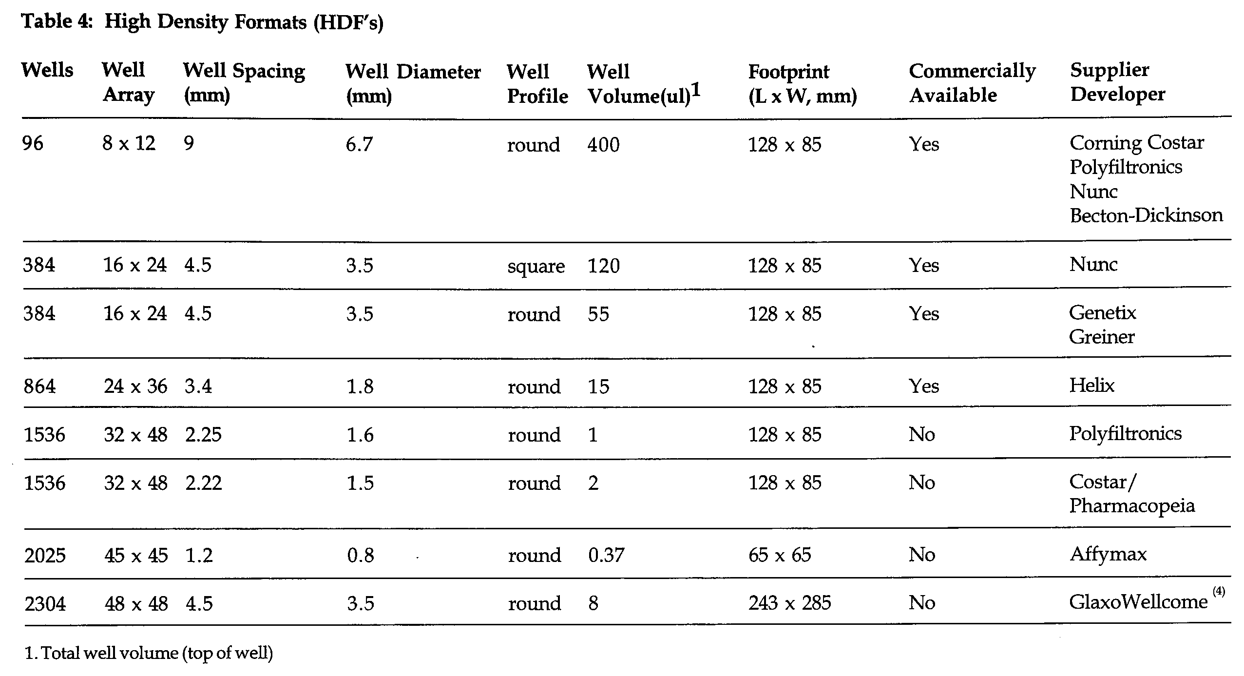
A high-density format is defined as an assay format with a well density greater than the conventional 96-well microtiter plate (MTP). Formats currently under consideration are summarized in Table 1. Many of these formats were originally developed for genomics research and have only recently been applied to HTS. Currently, most HTS work is being done in 96-well formats with the move to 384 well plates progressing rapidly. In fact, many groups are considering skipping the 384 format entirely and moving to the next higher level (864/1536). For example, Pharmacopoeia, in collaboration with Corning Costar (Cambridge, MA), is actively pursuing the 1536 format for HTS (1,2). Some groups have been developing even higher density plates, up to 9600 per plate, but this creates even more challenges in terms of liquid handling and detection. For example, a 370 nL volume plate has been used to screen combinatorial libraries such that only a few beads are placed in a well ( 3 ). An alternative is to break out beyond the MTP footprint, as is the case with the 2304 well BioSheet, a format originally developed for high density combinatorial chemistry ( 4 ).
Challenges for Liquid Handling
The well volumes shown in Figure 2 point to one of the most critical challenges for enabling high-density formats: delivery of reagents to the wells. In addition, once the reagent is delivered, it must be mixed and must not evaporate.

Schematic comparison of the types of inkjet technologies
Nanoliter Dispensing
The delivery of submicroliter or nanoliter volumes of reagents to high-density wells is necessary since most assays require the addition of several reagents to the assay mix. For example doing a 10 μL assay in a 384 well plate could require the following dispenses:

In this example, all but one of the dispenses would be difficult if not impossible using current liquid handling instrumentation. Since the compound to be screened is usually stored in an organic solvent, typically DMSO, it needs to be dispensed in small volumes to keep the final concentration of organic low, typically 1%. Although intermediate dilutions can be done, nanoliter dispensing affords direct dilution of the compound from its storage solution. Nanoliter dispensing of receptor or enzyme reagents is also important in cases where dilution of the reagent decreases its stability over time.
Assays in HDF's using conventional syringe-pump based liquid pipettors will be difficult for several reasons: 1) Most pipettors cannot accurately and precisely aspirate and deliver nanoliter volumes, 2) The delivery tip can consume a significant portion of the well volume creating overflow, and 3) Accurate and repeatable alignment of needles with the wells can be problematic. Thus a new dispensing technology is needed for high-density formats.
One such technology is inkjet dispensing, based on the technology used in the inkjet printing industry. All inkjet technology uses some means of compressing a liquid against a small orifice creating sufficient linear velocity to eject the fluid in the form of a drop. Inkjet technologies differ by the means used for creating the compressive force, as shown in Figure 1. Thermal inkjet technology, made popular by Hewlett-Packard (Sunnyvale, CA) inkjet printers, heats the fluid (ink) with a resistive element causing it to expand against the orifice. Solenoid inkjet technology uses gas or hydraulic pressure to compress the fluid against an inkjet valve. Gas provides an inexpensive source of pressure but can be less accurate as compared to hydraulic pressure. Hydraulic pressure, generated through the use of a syringe pump, permits accurate displacement of the fluid and is more amenable to aspiration. Opening the solenoid valve for several milliseconds produces an acoustic or pressure wave which increases in linear velocity as it passes through the orifice. Piezoelectric inkjet technology uses a piezoelectric crystal coupled to a liquid reservoir (e.g. a glass capillary). Biasing the crystal causes the reservoir to compress and eject the liquid from the orifice. Several groups are currently pursuing these forms of inkjet technology for a variety of dispensing applications (Glaxo Wellcome (Research Triangle, NC), Cartesian Engineering (Durham, NC), Packard Instruments (Meriden, CT), Pharmacopeia (Princeton, NJ), Microfab (Plano, TX)).

Captured video image of liquid dispensed from an inkjet dispenser. Orifice, 175 μm; well diameter, 3.5 mm; dispense volume, 8 μL.
A comparison of the different inkjet technologies relative to their use in HTS is shown in Figure 1. Because of the heating required and the difficulty in aspiration, the thermal inkjet mode is not suitable for application to HTS. Piezoelectric and solenoid based dispensing are the most amenable technologies for delivery to high-density formats. Because of its cost and simplicity, solenoid dispensing has been the first to be commercialized for HTS.
The use of inkjet technology for HTS will provide the following advantages over syringe-pump based liquid handling:
Accurate and precise aspiration and delivery of nanoliter volumes of reagents,
Rapid delivery of reagents resulting from non-contact dispensing and rapid valve actuation, and
Reduced requirements for alignment due to non-contact delivery.
Dispense Speed
Increasing the number of wells per plate increases the total dispense time per plate. Inkjet dispensing can reduce the dispense speed in two ways: valve speed and non-contact dispensing. Valves used in inkjet dispensing can operate at very high speeds. The following table shows typical values for dispense rate (volume/time):

Image of 864 well plate with cross hairs aligned to well A1.
Typical Values for Dispenserate

Although piezoelectric actuators can deliver drops at a rate of 10,000 drops/second, these high frequencies are not reliable for a wide range of fluid types.
Inkjet dispensing tips do not need to come in contact with the solution in the well. The linear velocity of the fluid leaving the orifice is sufficient to overcome the surface tension of the fluid. Non-contact dispensing can, in certain cases, eliminate the need for washing between dispenses. Table 6 summarizes speed differences between conventional syringe pump dispensing and inkjet dispensing. For most dispensing needs, inkjet technology has a clear speed advantage (more than a factor of 50 in one case). It is only when the dispenser must be washed after each dispense that this speed advantage disappears (e.g. aspirate, single dispense).
Mechanical Alignment
Alignment of dispenser tips to the well is trivial with a 96-well plate. However, with high-density formats, this alignment becomes more critical and difficult. The requirements for alignment become less stringent with inkjet dispensing due to the non-contact nature of the dispense. The size of the dispense element (drop or stream of fluid) emerging from the tip, not the tip itself, determines the level of alignment necessary. In other words, for a given well diameter, the smaller the element of fluid dispensed from the tip, the less critical the alignment. The following table shows the drop diameter as a function of drop volumes:

Image of transmitted light through a BioSheet using a cooled CCD camera. Experimental: CCD specifications, 1024 × 1024 pixels, 16-bit per pixel; exposure time 100 seconds; light source, quartz halogen lamps (from below); filter, 420 nm bandpass filter (on camera lens); solution, fluorescein.

Integration of wells from image in to produce 2304 values (48 × 48). Experimental: integration software, LabView with Concept V.i.; pixels per well, 3D; plotting software, Deltagraph.
Drop Diameters as a Function of Drop Volume

This table also shows that for some formats (e.g. 864), the dispense volume from an inkjet dispenser should be in the mid-to-low nanoliter range to enter the well (e.g. 1.8 mm diameter). Figure 4 shows the size of a dispense element (stream of liquid) relative to the well of a BioSheet. As can be seen, the liquid stream diameter (approx. 0.2 mm) is much narrower than the well diameter (3.5 mm).
One approach to alignment is to align the dispense tips to the format holder. However, this may not be sufficient given the non-uniformity and deformation of the plastic material of the format. Another approach, although more costly, would utilize a video camera for alignment to these high-density formats. Figure 3 shows a video image of a 864 well plate where a video camera was aligned to well A1 of the plate. Once the offset between the camera and the dispense tips has been determined, alignment of the wells with the cross hairs of the camera provides accurate alignment for the dispense.
Liquid Level Sensing
Conventional liquid level sensing is accomplished by measuring a shift in conductivity upon the dispensing tip entering the solution. This can be used for higher density formats if the tips can be aligned and place into the wells without overflow. As with dispensing, this challenge may require a new technology. If inkjet dispensing is used, the dispense could be verified by monitoring the drop breaking a beam of light. Alternatively, optical measurements of the liquid in the well may be able to confirm the presence of liquid. The above approaches, however, would only provide qualitative information (i.e. dispense yes/no).

Image of fluorescent emission in 384 well plate filled with different concentrations of fluorescein (image courtesy of Peter Ram, Imaging Research).
Mixing and Evaporation
The small volume of high-density formats presents a challenge for effective mixing of dispensates within a well. Using an 864 plate as an example, if a solution containing a small molecule (diffusion coefficient = 1 × 10⁻⁵ cm2/s) were dispensed into a well containing 10 μL of solution, the time required for the molecule to diffuse to the bottom of the well (4 mm) is approximately 2 hours, assuming no mixing occurred due to the dispense.
One of the clear advantages of syringe pipettors is the ability to thoroughly mix the contents of a well by a series of aspirations and dispenses, However for high density formats, mechanical positioning of syringe needles into 1.8 mm diameter wells (864 plate) will be difficult. Mechanical shaking may facilitate mixing, but for liquids in a small well, surface tension forces dominate and inhibit liquid movement. The use of the inkjet dispensing techniques described previously may facilitate mixing due to the momentum of the dispensate entering the well. Also the use of multiple drops per dispense may increase mixing. These areas are currently being investigated.
The evaporation rate of a liquid in a well is proportional to the exposed surface area of that liquid. However, the relative loss in liquid due to this rate is proportional to the surface area to volume ratio. The following table compares the surface area to volume ratio for various formats:
Comparison of Surface Area to Volume Ratios

The table shows that decreasing the well volume will increase the relative amount of solution lost due to evaporation. For example, 400 μL of solution in a 96-well plate will take twice as long to evaporate to dryness as compared to 55 μL of solution in a 384 well plate because the former has approximately half the surface area-to-volume. The rate of evaporation may be altered by other factors such as well diameter and geometry. For example, the meniscus is a larger portion of the surface area for an 864 well plate as compared to a 384 well plate, thus creating a larger surface area. In contrast, for narrow wells, the movement of air above the liquid surface may be less and would reduce evaporation.
Challenges for Detection
As with the challenge for liquid handling, the smaller volume of the high-density formats creates challenges for detecting the optical readout of each well. The challenges for detection are in the areas of sensitivity, mechanical alignment, and speed.
Sensitivity
Conventional colorimetric detection of 96-well microtiter plates is accomplished by measuring the amount of light absorbed by a solution in a well relative to a blank. The absorbance, A, of the solution is given by Beer's law:

Assays using a radiolabel for the readout will exhibit less sensitivity as a result of a reduction in the assay volume radiolabel. One way to increase sensitivity for small volume assays involves increasing the label concentration. However, increasing the concentration of radiolabel mitigates the reagent cost savings afforded by assays in HDF's.
High Density Formats (HDF's)

Total well volume (top of well)
Comparison of inkjet dispensing technology for HTS
Speed Comparison Between Syringe-Pump and Inkjet Dispensing 1

Assuming 48 dispenses into 384 well plate using an 8-channel dispense head.
Syringe: 4s/dispense, inkjet: 0.5 s per dispense (includes translation time.
48–30 sec washes between syringe dispenses, no washes for inkjet.
4 aspirations, 5 sec each for both dispensers; 48–30 sec washes between syringe dispenses
48–5s aspirations, 48–30 sec washes for both dispensers
Fluorescence offers greater sensitivity due to lower background and the dependence on the intensity of the excitation source. The fluorescent intensity, F, is dependent not only on path length, b, but the intensity of the excitation beam, IO:

where K is a constant relating to quantum efficiency of the fluorophore and the collection efficiency of the optical system. Thus for a given pathlength, the fluorescent intensity will be proportional to the excitation intensity, up to the point of photobleaching of the fluorophore.
Recently, several fluorescent assay technologies have been developed which would be amenable to high-density formats. Fluorescence polarization ( 5 ) measures polarized fluorescent light emitted by a label and relates the extent of polarization to the extent of binding. Time-resolved fluorescence techniques (TRF, HTRF) (6,7) use the extent of energy transfer between a lanthanide donor and a phycobiliprotein acceptor to measure the degree of binding. Fluorescence correlation spectroscopy ( 8 ) measures the diffusion of a molecule through a small probe volume and relates the diffusion rate with the extent of binding.
Mechanical Alignment
Conventional plate readers detect the absorbance or fluorescence from each well by aligning a photosensitive element (photodiode or photomultiplier) to the well. With high-density formats, detection of signal from a well without interfering signal from adjacent wells (crosstalk) will be a critical challenge. Several approaches using conventional instrumentation are possible: 1) reduce the size of the illumination source (e.g. a laser spot in each well) or 2) reduce the size of the photosensitive element (fiber optic probe).
One way to eliminate mechanical alignment and crosstalk problems is to image the entire format using a CCD camera. From an image, one can integrate the pixel values corresponding to the locations of the wells. Fig. 4 shows an image of a format, the BioSheet, comprised of 2304 wells in a 48 × 48 array. The image was acquired using a cooled CCD camera and the pixel values of each well, representing the amount of light absorbed by the solution in each 8 μL well, were integrated and plotted, as shown in. Fig. 5. Alternative to the imaging of light transmitted through the plate is to image fluorescent emission from the wells, as shown in Figure 6. Although more sensitive than absorbance, as shown above, fluorescence requires more sophisticated optics for proper fluorophore excitation and collection of omitted radiation.
Speed
With an increase in the number of wells with high-density formats, the time required to read the entire format will increase. Reading time can be reduced if the number of photosensitive elements is increased (e.g. a row of elements moving across the format vs. a single element moved to each well). The ultimate extension of this concept is the use of an imaging detector, as described above. With the appropriate light levels, an image of a format can be acquired and analyzed in a matter of seconds.
Conclusion
The use of high-density formats (HDF's) is essential to increase the throughput and reduce the costs of high throughput screening. Implementation of these formats will present formidable challenges, which will require new techniques and technologies (Table 4). For dispensing, inkjet technology represents the best choice for the quantitative delivery of nanoliter volumes (Tables 5 and 6). For readout, CCD imaging is an attractive technology for rapid, parallel detection of high-density formats.
Footnotes
Acknowledgment
The authors gratefully acknowledge Glaxo Wellcome, Inc., Research Triangle Park, NC, for the support for this work.
1.
J. Burbaum, “Implementation of Microvolume Assays in High Density Microtiter Plates”, Lab Automation '97, San Diego, January 19, 1997.
2.
J. Burbaum and Nolan Seigel, New Technologies for High Throughput Screening,
3.
J.R. Schulleck, J.H. Butler, Z-J Ni, D. Chen, and Z. Yuan, A High Density Screening Format for Encoded Combinatorial Libraries,
4.
A.V. Lemmo, J.T. Fisher, H. Mario Geysen, and D.J. Rose, Characterization of an Inkjet Chemical Microdispenser for Combinatorial Library Synthesis,
5.
W. Jiskoot, P. Hoogerhout, E.C. Beuvery, J.N. Herron, D.J.A. Crommelin, Preparation and Application of a Fluorescien-Labeled Peptide for Determining the Affinity Constant for a Monoclonal Antibody-Hapten Complex by Fluorescence Polarization,
6.
G. Mathis, Rare Earth Cryptates and Homogenious Fluoroimmunoassays, Clin. Chem. 39 1953–59 (1993).
7.
E. Lopez, C. Chypre, B. Alpha, G. Mathis, Europium (III) Trisbipyridine Cryptate Label for Time-Resolved Fluorescence Detection of PCR Products Fixed on a Solid Support,
8.
R. Rigler, Fluorescence Correlations, Single Molecules Detection and Large Number Screening: Applications in Biotechnology,