
Abstract
An electromagnetic microvalve for pneumatic control of microfluidic devices has been designed, fabricated, and tested. The microvalve is composed of two parts: a miniature electromagnetic actuator and a valve body. The electromagnetic actuator consists mainly of a thin polydimethylsiloxane (PDMS)–based elastomer, which acts as the valve diaphragm. The diaphragm, used as a solid hydraulic medium, converts the large contact area of a valve core into a small contact area of valve head while maintaining a large stroking force. This microvalve remains closed because of a compressed mechanical spring force generated by the actuator. On the other hand, when a voltage is applied, the valve core moves up, relaxing the thin PDMS membrane, opening the microvalve. The fast open response (~17 ms) of the valve was achieved with a leak rate as low as 0.026 sccm at 200 KPa (N2) pressure. We tested the pertinent dynamic parameters such as flow rate in on/off mode, flow rate of duty cycles, and actuated frequencies in pulse width modulation (PWM) mode. Our method provides a simple, cheap, and small microvalve that avoids the bulky and expensive external pressure control solenoid manifold. This allows it to be easily integrated into portable and disposable devices.
Keywords
Introduction
Microfluidic devices consist of micromixers, microvalves, micropumps, microchannels, and so forth. The full integration of these systems allows for quick fluid transfers and increased portability. There are various kinds of actuation methods developed for microdevices on a microfluidic chip to control the small-volume output of chemical or biological working fluids. These include piezoelectric, 1 electrostatic, 2 magnetic, 3 thermo-pneumatic 4 and pneumatic 5 actuation, among others. The pneumatic actuating microvalve is preferably applied in elastic materials, such as polydimethylsiloxane (PDMS)–based systems. The key merits of PDMS materials include transparency, remarkable mechanical behavior, simple structure bonding process, and low production cost. One exception is pneumatic actuation microdevices, which usually use actuators located outside the fluidic chips while other actuators must be embedded in the microfluidic chips. The bulky volume of actuators will definitely affect the degree of microfluidic Large-Scale Integration (mLSI). The control system and pressure generation are usually hosted off the chip for the pneumatic microchip. Therefore, it becomes possible to develop a microfluidic chip with thousands of integrated micromechanical valves, pumps, and other control components. Hong and Quake 6 developed such a microfluidic chip with a high density of pneumatic valves and pumps for parallelized, high-throughput screening of fluorescence-based single-cell assays. This type of chip embodies the real meaning of a “factory” chip. 6 The small size and pneumatic actuation allow for dense integration in a single microfluidic chip.
However, there is still much work to be done on pneumatic microfluidic chips (PMC). A pneumatic control system auxiliary to the PMC is needed to support the implementation of the pneumatic actuation.7,8 Although the microfluidic systems themselves have a small footprint, the necessary support equipment is often bulky and nonportable. The outside pneumatic control system usually includes a supply source of compressed air, a solenoid valve array, a sensor, and a controller unit/PC. For example, many microfluidic systems rely on external valves to drive valving internal to the microfluidic chip. As the number of internal valves can run into the hundreds, or even thousands, the number of external valves and the size and cost associated with them are a significant problem. Thus, the development of the actuation and control elements for the internal microfluidic components has not kept up with the miniaturization of microfluidics.
To avoid the usage of an external pneumatic control system for PMC, some general approaches are presented. The Whitesides research group 9 experimented with a torque-actuated valve that directly used small machine screws to press on PDMS microchannels for controlling fluid flows. Also, Zheng et al. 10 studied a screw-actuated pneumatic valve, which, by turning the machine screws up and down for pressure control in the control channel filled with water, increased pressure, leading to collapse of the PDMS membrane into the microfluidic channels and control of the flow of fluids therein. One of the drawbacks of these last two microvalves is that the valves cannot be operated automatically because of the required slow manual manipulation. Sia and coworkers 11 used a modified solenoid with a microcontroller and peripheral circuitry instead of a manual screw-actuator mentioned in Zheng et al., 10 to solve the problem of slow manual manipulation. However, the microvalve via liquid-filled control channel cannot be reused because of the evaporation of water through the surrounding PDMS wall in a very short span of time (less than 24 h), and refilling liquid into the control channel would be needed for at least 48 h to cure the sealing membrane. Another way of solving the problem of a bulky external air supply and its control solenoid valves is a thermo-pneumatic PDMS microvalve, used with a heating electrode, which can be coupled to a flexible membrane for generating an on-off valve that requires a simpler control circuit and less peripheral equipment. 12 However, the thermo devices can generate high temperatures and destroy the bioactivity of the biological reagent. Phase change valves based on the paraffin solid-liquid phase transition are reported in references 13, 14, and 15. The devices with an integrated two-level cooling/heating system are simple to operate, and valve operation is relatively slow. The Takayama research group16,17 proposed a microvalve integrated with multilayer soft lithography technique and controlled by Braille display equipment, instead of pneumatic actuators. The disadvantage of the Braille actuator is its inflexibility in one sense because of the position-fix movable pins. A polyvinylidene fluoride (PVDF) microvalve for gas flow control was designed by Wiederkehr et al. 18 to control the gas flow rate with piezoelectric actuators through a glass micronozzle. The drawbacks are a complicated microeletromechanical systems (MEMS) processing method for rigid material used in valve body and high-voltage DC300V. Anjewierden et al. 2 developed an electrostatic microvalve for pneumatic control of microfluidic systems, which was able to diminish the external actuation solenoid valves for gas serving. However, the disadvantage is a huge footprint for the final assembled device, with its two 75 mm long valves, polymethylmethacrylate (PMMA) valve plate, and high power that has an actuated voltage even higher than 680 V. Such a system would not allow for a portable, low-power system with integrated controls.
The purpose of the research presented here is to design a microvalve that is inexpensive, easy to manufacture, has a small footprint, can function as an external valve controlling a pneumatic internal valve, and can be easily integrated with a complex polymer microfluidic system. Electromagnetic actuators were chosen for this work because these actuators have low power consumption, have a fast response time, and operate at ambient temperature. Most electromagnetic microvalves are used to control the gas flow and liquid flow, but the purpose here is to control gas flow without the use of a bulky and expensive solenoid array.
What is unique about the valve presented in this article is not only that it takes advantage of PMC, in which the control system and pressure generation is usually off chip, but also that it avoids the huge off-board solenoid valve array—usually part of the outside of the pneumatic control systems. The electromagnetic valves in this article can be manufactured and integrated into a valve array, which can be a portable, low-cost, and integrated module located outside the PMC. Another important advantage is that the structure and the packaging process of the valve are very simple, using soft lithography technology with material common in microfluidic fields—PDMS, and therefore the valve is very fit for mass production and commercialization.
In this article, we present the design, fabrication, and experimental results of the electromagnetic microvalve, and its electromagnetic-static behavior and electromagnetic-fluidic behavior using N2 flow under differential pressures, duty cycles, and frequencies. The measured results suggest its application to PMC because its differential pressure is fully able to meet the PMC’s integrated valve array and can minimize the outside pneumatic control system.
Working Principle and Design
Selecting an actuator is an important part of the microvalve design. Not only does its size affect the whole volume of the microvalve but also its reaction speed, power consumption, and work environment directly determine the characteristics of a microvalve. An electromagnetic actuator is suitable for the microvalve because it has a larger displacement, is suitable for linear control, and has faster actuation and lower power usage than other popular actuators used in microfluidic systems.
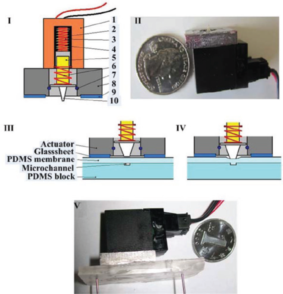
The schematic of the electromagnetic actuator is shown in Figure 1I . It shows that the actuator consists of several main components. The moving iron can move 100 µm up and down. The valve core initially projects downward 100 µm lower than the lower surface of the glass without voltage and the return spring is in a free state. The valve core moves up when voltage is applied because of electromagnetic suction between the moving iron and the static iron. The valve core is parallel with the lower surface of the glass slide, and the return spring is in a compressed state. Then, without voltage, the valve core moves down under the action of the return spring to the initial state again. The total size of the encapsulated actuator is 20.5 × 12 × 9.5 mm, as shown in Figure 1II . Compared with the microchannel size (µm), the footprint of the electromagnetic actuator is a little bigger. However, it is much smaller than other actuators used in microfluidic fields, such as the piezoelectric actuator (deformation of 90 µm, need a length size of 90 mm) and linear steering engine (25 × 22 × 20 mm, miniature GS-1502, size after encapsulation into the adaptive actuator).
(
The basic structure of the microvalve is shown in Figure 1III (the top is the electromagnetic actuator with a valve core, the bottom is the PDMS block with a microchannel, and the middle layer is a soft PDMS thin film, which also acts as the valve diaphragm). The valve core and the diaphragm consist of the valve head, which can close or open the microvalve. As shown in Figure 1IV , the microvalve is normally closed because of the return spring, which makes the middle diaphragm bend down and the microvalve close. We designed the normally closed electromagnetic microvalve here, because it can automatically separate the air supply and the microchip and set the microchip to a very safe state if electrical power to the microvalve fails for some reason. The valve head moves up when a voltage is applied, the deflectable diaphragm recovers because of its elasticity, and the air flows through the microchannel. With the voltage off, the deflectable membrane deflects downward to seal off the gas channel, fully closing the microvalve.
In this article, a simple polymer-based solid-hydraulic amplification (SHA) theory 19,20 is used to minimize the displacement of the valve core. Figure 2 shows the principle of the SHA mechanism. It is assumed that the volume change of the hydraulic chamber is negligible and the hydraulic material is treated as incompressible. When a force is applied axially to the upper surface of the hydraulic filling material, making it undergo a small displacement downwardly, the bottom surface of the incompressible undergoes an amplified displacement. The transform ratio T is defined as the ratio of the displacement of the bottom and the top opening and is inversely proportional to the ratio of the areas at the top and bottom. The valve core has a diameter of 1 mm; the width of the rectangle microchannel is 500 µm, and the valve membrane is a 100 µm soft PDMS film. In this article, the ratio of the displacement of the valve core (d1) and the valve head (d2) is inversely proportional to the ratio of the contact areas between the PDMS valve diaphragm top and valve core (A1) and between the microchannel bottom and the PDMS diaphragm bottom (A2) when the microvalve is closed. Thus, T is equal to 1.57.
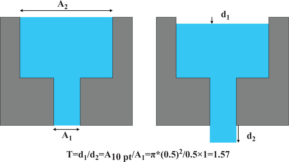
Principle of the solid hydraulic amplification mechanism.
As Wu et al. 19 demonstrated, there are two assumptions upon which the SHA concept is based: the negligible volume change of the gas chamber (volume of microchannel) and the zero-volume change of incompressible material under small deformations. In this article, there is no special SHA media or special volume for the designed microvalve; instead, the middle PDMS membrane and air microchannel act as these components separately. In previous literature reporting on the SHA scheme, sealing circumvents is a big fabrication challenge on the microscale. However, the simple principle used a similar SHA scheme to avoid the manufacturing sealing problems, and the similarity and the measurement results will be shown in the Experimental Results section.
Materials and Fabrication
The designed electromagnetic microvalve includes two subsystems: a valve body portion and an electromagnetic actuator, which can be fabricated separately and assembled. Using a soft lithography process involving thick-film micromachining and replica molding of elastomeric materials, the valve body can be fabricated. The electromagnetic microvalve body is made of PDMS elastic material, because of its key merits. Most importantly, the transparent property of PDMS enables the optical detection of microfluidic devices, which is crucial for using the actuator to press directly on a PDMS vale body with naked eyes. Furthermore, the low Young’s Modulus allows large deflections, good sealing properties, and excellent toughness, making it the perfect material for the valve membrane.
The soft lithography process appears extensively in the literature on microfluidic systems.21–23 However, in this article, the ratio, cured temperature, and specific details are different from previous processes. The silicon mold production process is the same as in the previous literature and is not described here again. The fabrication starts with the PDMS valve membrane, which is spin coated on the planar side of a silicon wafer, spin coating a 100 µm thickness PDMS from a prepolymer solution (Sylgard 184, base/curing agent 15:1; Dow Corning Corporation, Midland, MI). To protect the mold, the surface of the silicon/photoresist master is treated with chlorotrimthylsilane (A13651, 25 mL, [CH3] 3ClSi; Alfa Aesar Corporation, Ward Hill, MA). The purpose of silanized treatment is also to prevent excessive air bubbles when spin coating. Then, the filled mold is cured for 3 h at 65 °C in an oven. Less curing agent of prepolymer and a longer and lower cured temperature can increase the membrane toughness. The air channel and its PDMS slab were made by replica casting of prepolymer solution (base/curing agent 5:1) on a silicon mold, which is then cured for 30 min at 80 °C in an oven. More curing agent of prepolymer, and a shorter and higher cured temperature, can improve the plasticity of the thick PDMS slab and help it better support the whole microvalve role. The different ratio of the two layers of cured PDMS also has a significant influence on the bonding strength.
The method for sealing microfluidic chips made from PDMS material is much easier and simpler than that used for other commonly used rigid materials, such as glass, Si, and SiO2. It includes reversible and irreversible seals for PDMS microfluidic chips. The drawback of the reversible seal is that the device is not sealed tightly, but because it can be dismantled and the channels cleaned after use, it is very useful for microfluidic chips that need to be reused. The methods of irreversible seal include oxygen plasma treatment bonding,24,25 partial curing bonding, 26 and PDMS varying ratio bonding. 27 The shortcoming of the irreversible seal is that it results in an increased difficulty in cleaning the inside of the channel and that it creates a need for special packaging for the chips. However, because the latter method is sufficiently strong for the high-pressure PMC and the designed microvalve in this article does not need to be cleaned because of dry and clean air or N2 being used, the mix sealing of oxygen plasma treatment bonding and PDMS varying ratio bonding reinforces the seal strength. The PDMS slab and membrane are treated by a 50 W plasma for 2 min and then sealed irreversibly to form a microfluidic device that can sustain N2 flow of an applied pressure of 280 kPa without bursting open. This fully satisfies the air pressure needs of a PMC. Figure 3 shows the specific manufacturing process.
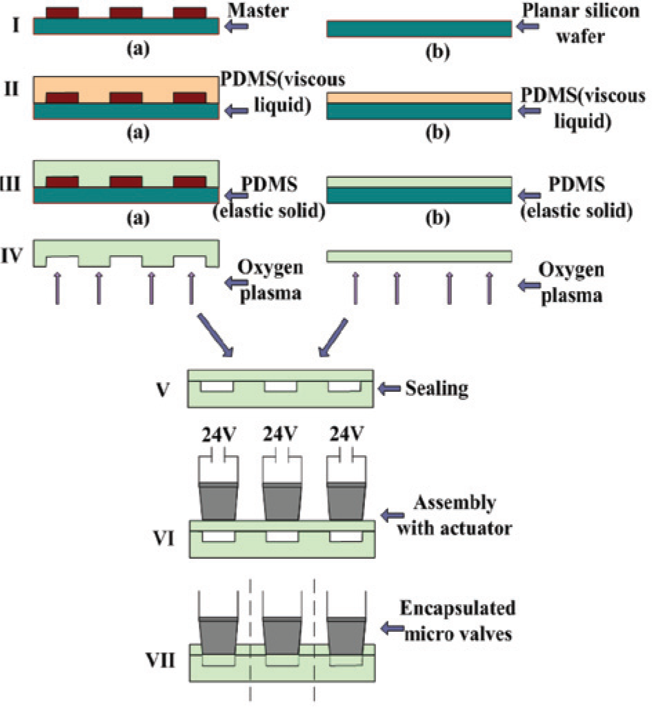
Protocol for manufacturing the valve body: air microchannel and polydimethylsiloxane (PDMS) block: (
The whole dimensions of the microvalve mainly result from the size of the electromagnetic actuator. However, to facilitate the measurement, the designed microchannel length is 30 mm, which easily connects with external gas systems, as shown in Figure 1V . What we really care about is the circular valve core, which has a 0.785 mm2 contact area and delivers about 0.5 N of force to the diaphragm. The magnitude of the force is measured by a dynamometer through the method of multiple averaging (for the theoretic calculation method, please refer to the reference 28). The thickness of the middle diaphragm is 100 µm, and typical cross-sectional dimensions are approximately 90 µm high and 500 µm wide for the microchannel in the bottom PDMS slab, which makes the valve intersections approximately 1000 × 500 × 90 µm. The actuator is actually an inhalation electromagnet with a moving iron post, which has an area of 0.785 mm2 and can function as part of the valve core. This is different from other electromagnetic microvalves29,30 in previous literature applications in microfluidic systems, which always need a variety of microsize parts made by the MEMS method, such as base and supported legs for the membrane and so on.
The compressed spring force is, in fact, applied by the electromagnetic actuator while the microvalve is in the closed state. This seating pressure is achieved using the following fabrication and assembly procedure: A voltage of DC24V is applied initially to the electromagnetic actuator during bonding onto the valve body, as shown in Figure 3VI . It is can guarantee good switching performance in the case of a center not fully aligned due to the redundancy between the diameter of the valve core and the width of the air microchannel.The optical transparency of the valve body can make the actuator directly press on a PDMS valve body with naked eyes. Once bonded, this assembly procedure ensures that the valve head is pressed downward for a fully closed microvalve.
Experimental Results
Electromagnetic-Static Behavior
Leakage Test of Bonding Device
A coarse detection method for the sealing strength of the PDMS device is given here. The inlet of the microvalve is connected to a gas supply. The outlet tube is closed by a cured PDMS block, and the device is kept slightly submerged in the deionized water. The decompression device on the gas tank is regulated from 0 until to 280 KPa. There is no continuous or large bubble overflow that can be detected by the naked eye. After 20 min, there is no significant change in the numbers on the digital pressure gauge. This indicates that the designed microvalve can sustain a gas flow of an applied pressure of 280 KPa without leaking, which makes it fully able to satisfy the needs of PMC.
Leaking Rate of the Closed Microvalve
We have fabricated and assembled three microvalves with the same dimensions, materials, and technological process to study the microvalve performance. They have all shown similarly good performance when we tested for leaks under different pressures. We expended considerable effort in developing a protocol to test the valve for inlet pressures in the range from 0 to 200 KPa in 10 KPa increments. The pressure range (0–200 KPa) can completely meet the needs of commonly used PMC and will be used for all of the following performance tests.
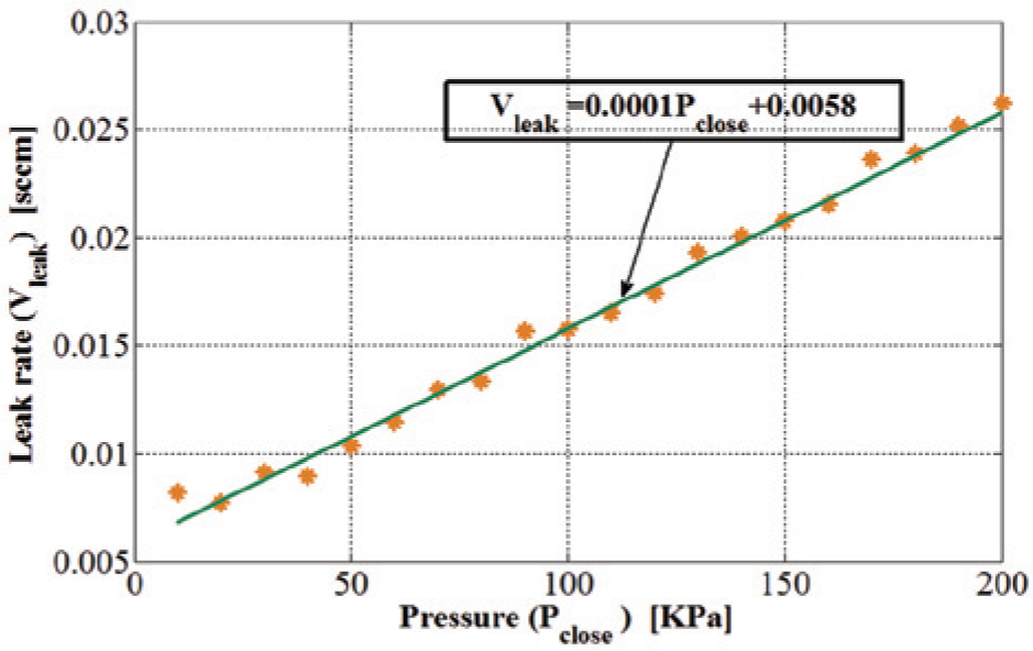
To measure the leaking rate of the microvalve, the flow rate sensor (ASF1430, Sensirion Company, Staefa, Switzerland) was used. The inlet of the miniature gas is connected to a gas supply, the outlet tube is connected to a port of the flow sensor, and another port of the flow sensor is connected to the atmosphere. The elastomeric valve membrane is responsible for the extremely low leak rates. The accuracy of this leaking measurement is approximated as the lowest setting rate of the micro air flow sensor, ≈0.0143 sccm.
Leak testing of a microvalve using a micro flow sensor showed an extremely low leak rate of 0.026 sccm at an inlet pressure of 200 KPa. While the microvalve is closed, the leaking rate is determined from the inlet pressure. Figure 4 shows the leak rates of the microvalve for various inlet pressures. The return spring and the thin membrane, which work like a gasket in a macroscopic valve and use rubber washers as valve seats, are responsible for the high seating pressure and the extremely low leak rates. 5 Figure 4 also shows that the trend of (Vleak) is in the range of 0 to 0.026 sccm over Pclose of 0 to 200 KPa.
Leak rate of the microvalve under the on/off mode.
Operating Lifetime of the Valve Memebrane
All three microvalves were used in the valve membrane lifetime experiment. According to our experiences on the repeat test of wear, the valve diaphragm is punctured for 2 h at 50 Hz. The two other valves have no noticeable puncture phenomenon of PDMS and structural failure. After the test is continued for another 1 h at 50 Hz, the two microvalves are still in good condition. The unsuccessful diaphragm may have been caused by the uneven mixing of prepolymer solution before curing, which results in uneven strain. The test results can guarantee the high repeatability and the reliability of the microvalve without a mechanical failure of the whole device and the puncturing of the valve diaphragm in the small strain region.
Response Time of the Electromagnetic Actuator
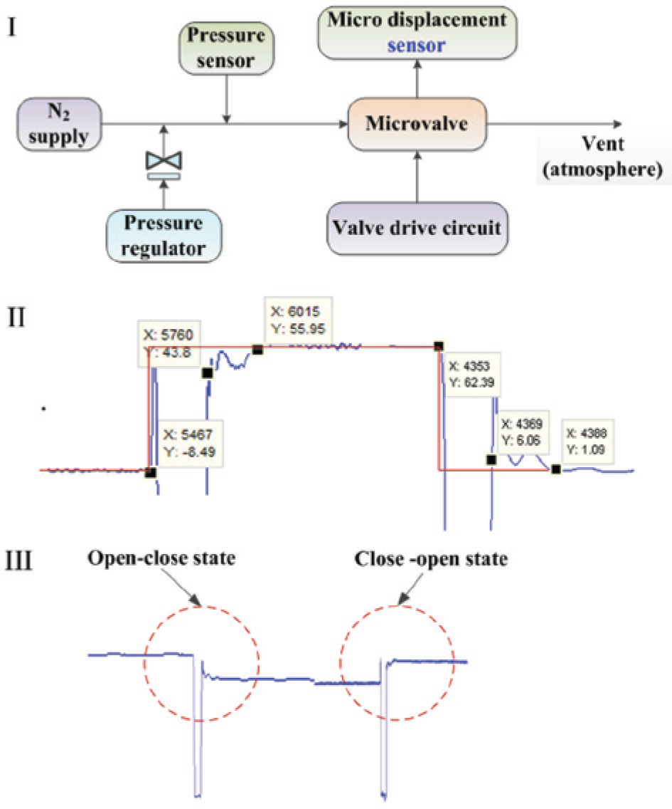
To measure the response time of the microvalve, a micro displacement sensor (LK-G5000, Keyence Company, Osaka, Japan) was used to observe the displacement so that the response time of opening or closing the actuator can be seen, as shown in Figure 5I . The changing displacement of the valve core is largest when the valve is fully closed or fully opened, when the microvalve was driven at a voltage of DC24V. Figure 5II shows the displacement change and the response time of the actuator voltage on and voltage off, respectively, as well as the opening time and closing time of the microvalve. From the test screenshot, we also can see clearly that the opening and closing time of the microvalve appear to be different. When there is no flow, the opening microvalve response time is about 17 ms, whereas the closing microvalve response time is about 293 ms. A longer closing response time may have resulted from larger suction that produces a displacement in the opposite direction at the moment the power is turned on or off, as shown in Figure 5III .
(
Displacement of Valve Core
The valve core and the valve diaphragm consist of the valve head, which can open or close the microvalve when the actuated voltage is applied or unapplied. The mechanical response of the microvalve is measured. Figure 6 shows the experimental displacement of the PDMS valve core as functions of the unapplied voltage, which is 61.72 µm when the microvalve is fully closed. Because the depth of the microchannel is 90.3 µm, and, according to the SHA theory, the transform ratio is T = 1.57, the theoretical largest displacement of the valve core should be 57.52 µm. The subtle differences may be because of an imprecise first assumption based on SHA theory. We also measured the displacement of the valve head using a manual adjusting device under different valve-opening degrees. The adjusting device will be introduced in detail in the next section.
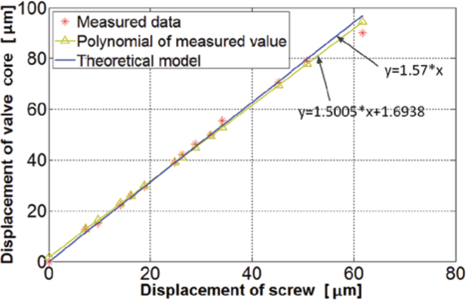
Measured displacement of the valve core.
Electromagnetic-Fluidic Behavior
Flow Test under Different Valve-Opening Degree
The first tests performed were static flow tests. When the actuated voltage is turned on or off, the microvalve becomes immediately opened or closed, respectively. Therefore, to evaluate the pressure-flow characteristics under different valve openings, the microvalve was connected to a screw at the bottom of the electromagnetic actuator, which can adjust the valve opening. The exact valve head position could be determined via the micrometer M3*30 screw (GB818-85) as the manipulator, as illustrated in Figure 7 .
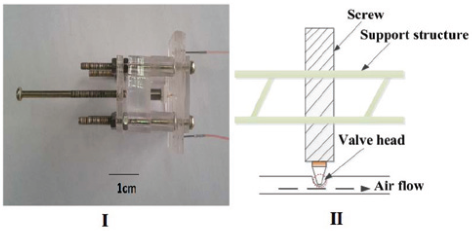
(
For pressure-flow characterization, the single microvalve outlet was open to the atmosphere, the inlet was connected to a pressure source, and the pressure and flow speed were measured by miniature pressure sensor (Xcl-080, Kulite Company, Leonia, NJ) and ASF1430 miniature gas flow sensor. The measured valve-opening degree-flow characteristics, shown in Figure 8 , confirm the valve’s potential for controlling large flows. Figure 8 also shows the displacement of the valve core (manual displacement) and the experimental displacement of the valve head (valve-opening degree).
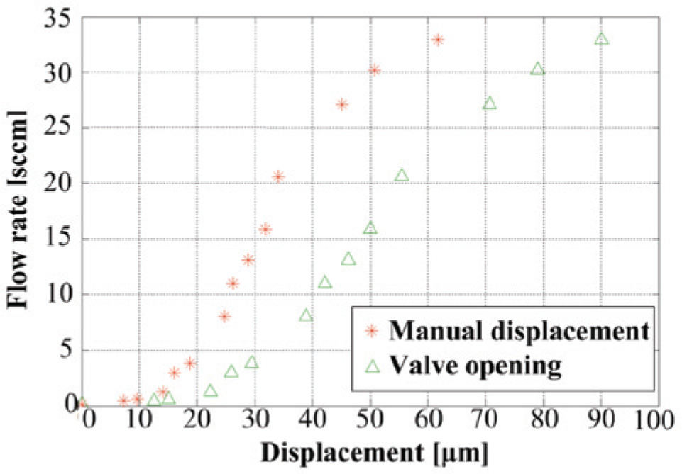
Manual measured valve-opening degree-flow characteristics under the differential pressure of 100 KPa.
Flow Test of Fully Open Microvalve
If the designed microvalve is fully open, the valve hole is the air channel. The volume flow rate Q can be determined from the formula in the literature 27 :
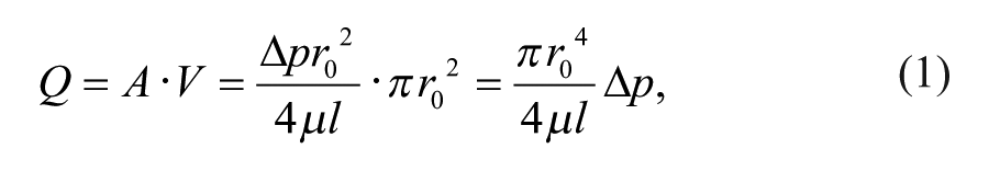
where
N2 flow rate of a single open microvalve.
The valve was characterized in on-off and pulse width modulation (PWM) working modes. For the on-off mode, the maximal nitrogen flow rate of 23.32 sccm was reached at 120 kPa differential pressure, and an open-closed flow ratio higher than 1370 was obtained. The measured static power consumption required to keep the microvalve fully open is about 500 mW at DC24V. This static power consumption is primarily needed to overcome the spring force keeping the spring in a compressed state in the actuator.
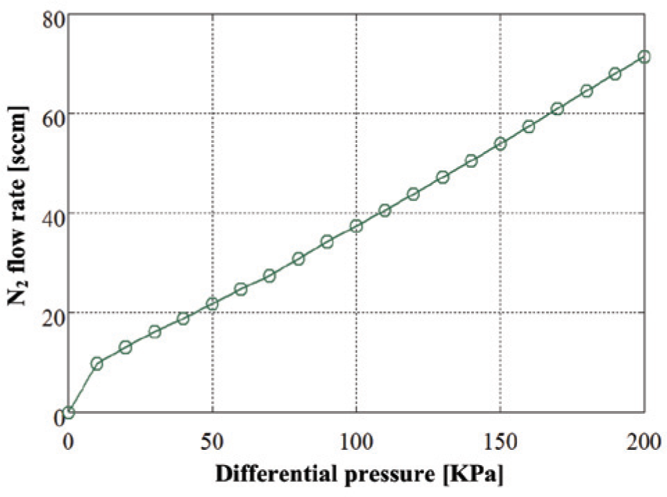
Duty Cycle
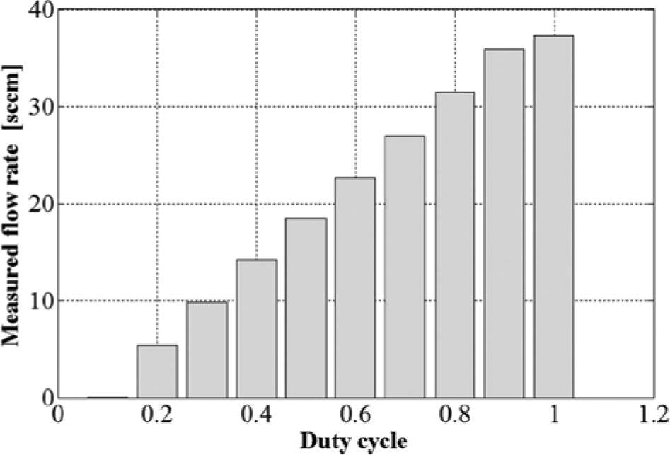
For varying the flow rate delivered by the microvalve, the microvalve can be actuated in PWM mode. The PWM mode resulted in a linear relation between duty cycle and flow rate. The dependence of flow rate on duty cycle is plotted in Figure 10 . A duty cycle of 0% means that the valve is fully closed, and a duty cycle of 100% means that it is fully open. Figure 11 also shows the flow rates at different differential pressures for a microvalve actuated in a pulsed mode. This figure proves that flow regulation was achieved at the frequency scope of 0 to 50 Hz. The highest dynamic flow rate achieved in this device was 37.31 sccm under the conditions of a differential pressure of 100 kPa, a 50 Hz peak-to-peak square wave drive voltage of DC24V, and a peak valve opening of 90.3 µm.
Flow rates versus duty cycle of a microvalve. The actuation frequency is 50 Hz, and the differential pressure is 100 KPa.
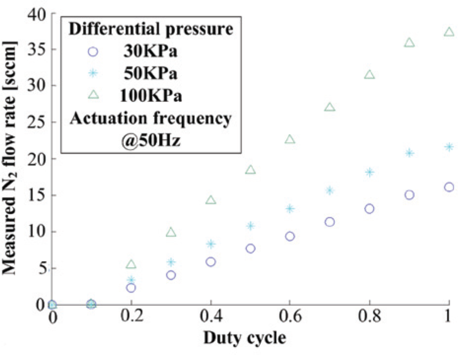
Measured flow rates of the designed microvalve actuated in a pulse width modulation mode at 50 Hz.
Actuated Frequency
Figure 12 presents the measured flow rates of N2 obtained for a valve-operating frequency from 0 to 50 Hz using a square wave actuation voltage with the same voltage amplitude. In the previous period, measurements made at a constant duty cycle and constant inlet pressure show that the flow rate drops with higher frequency operation because of the slow response time of the flow meter at high frequency. A similar cause analysis has previously been found for the flow rate of a piezoelectric microvalve. 31 The flow rate starts to drop gently when the actuation frequency is higher than 25 Hz. This drop may have been caused by the slow close response time of the microvalve. Because of this slow response time, the microvalve does not have enough time to fully close and instead begins to open, as shown in Figure 13 .
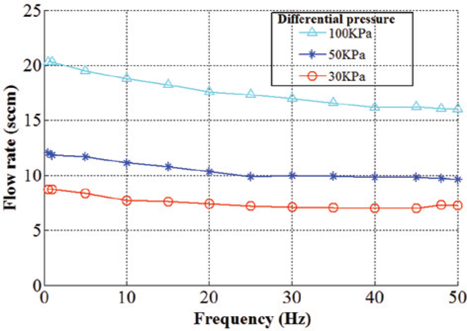
Measured N2 flow rate as a function of actuation frequency at differential pressures.
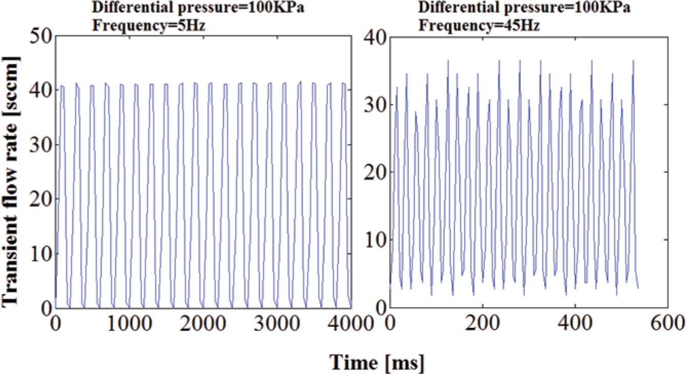
Measured transient N2 flow rate.
Integration with Microfluidics
Using a soft lithography process involving thick-film micromachining and replica molding of elastomeric materials, the designed electromagnetic microvalve can be fabricated. A three-way electromagnetic microvalve can be fabricated from two aforementioned microvalves arranged side by side and operated in a specific sequence. One port of the three-way microvalve connects the air supply, another port connects the vent, and the last port connects a pneumatic control channel of PMC. When the first valve is open and the second valve is closed, the pressure of the air channel increases; when the first valve is closed and the second valve is open, the pressure of the air channel decreases to near atmospheric pressures. Using the designed three-way electromagnetic microvalve can realize the real-time control pressure in a control channel of PMC.
Microfluidic large-scale integration is the technology used to integrate thousands of microvalves, pumps, and compartments in a single chip. This chip mainly consists of a flow channel and a pneumatic control channel that could be deformed under pressured gas to pinch off the flow of fluids above or below it in order to close the valve, which also acts as a pneumatic actuator, as shown in
Figure 14I
. The pneumatic actuator can be controlled by a designed three-way valve array, which also can be used for the pneumatic on/off valve, pneumatic pump, and pneumatic mixer, as shown in
Figure 14II
,
III
,
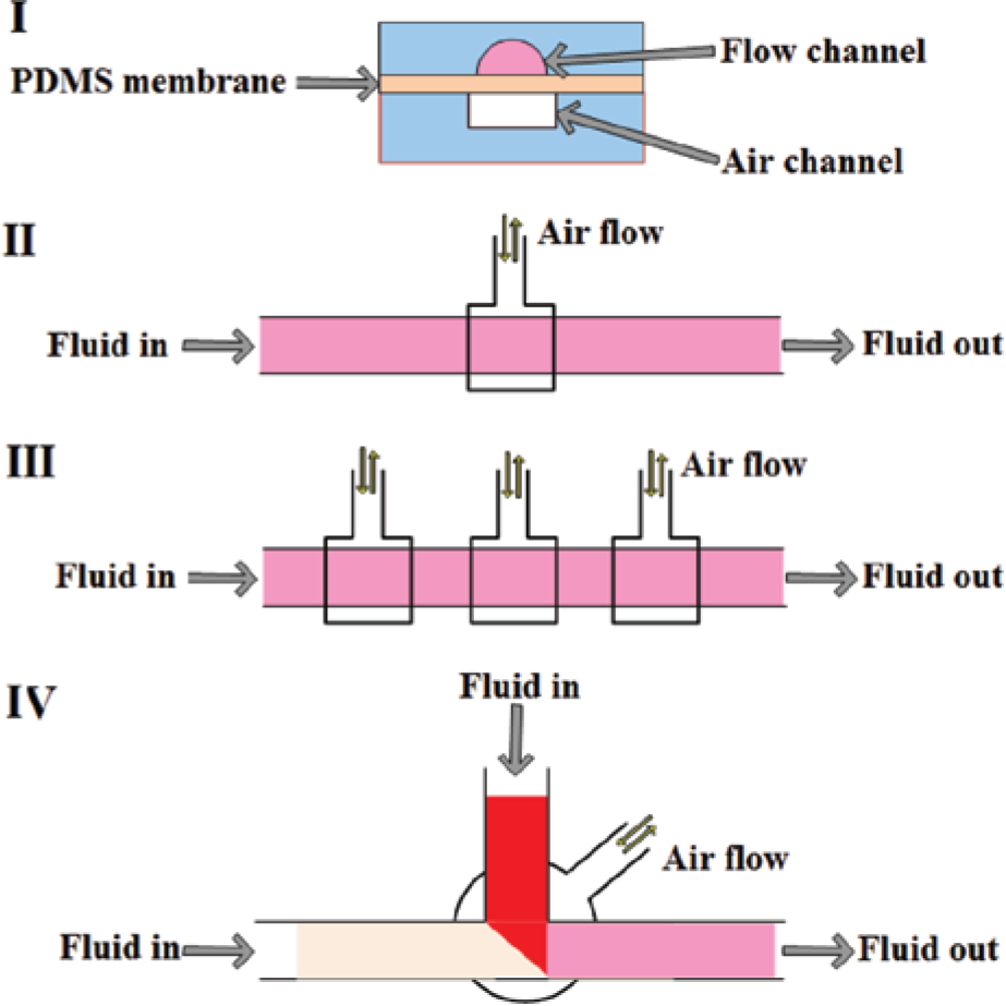
Schematic of electromagnetic microvalve for some applications.
In conclusion, a microvalve with a simple structure and the appropriate fabrication process and characterization results is presented. This microvalve is low powered and leak tight for precise gas flow rate control of the PMC. The simplicity permits the design of a valve body with small dimensions and the integration of a valve array that can act as a module outside of the PMC. The novel idea of eliminating the external solenoid valves, if executed, can help us realize the real meaning of mLSI for the whole PMC system.
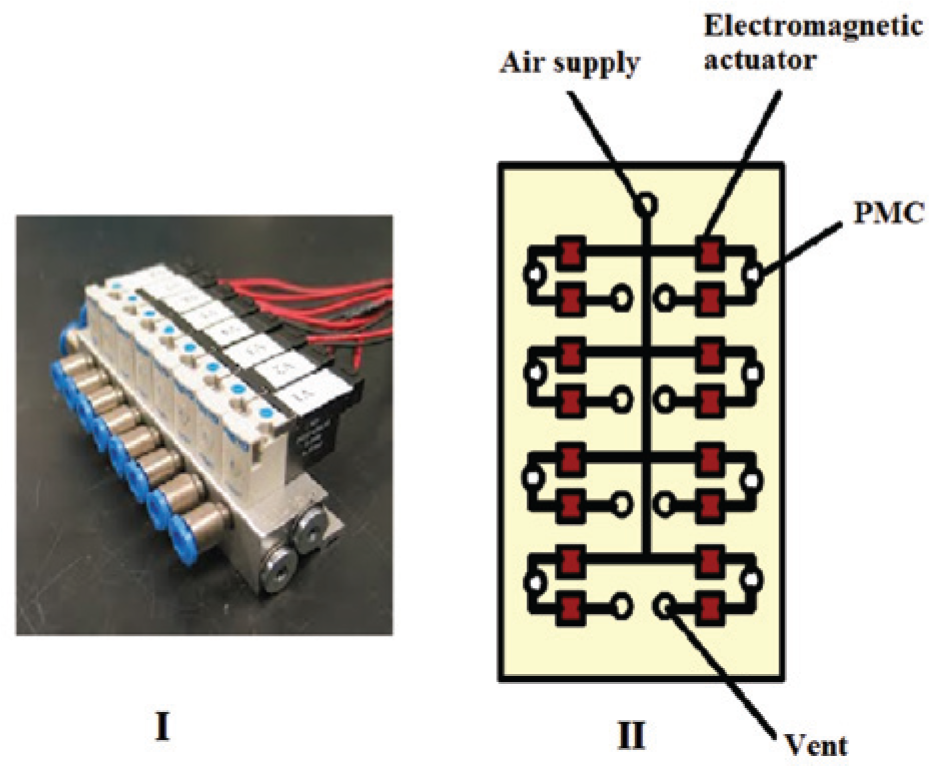
Further work needs to be done to reduce the overall size of the microvalve, as the designed performance can fully satisfy the demand of PMC. If smaller-sized actuators are developed, a simple and highly integrated valve array will be realized. Lower-voltage amplitude, which leads to lower power consumption, is another challenge. Future work on this project also will involve integration of an array of electromagnetic valves with an entire microfluidic system. The footprint (110 × 45 × 30 mm, including the substrate) of the proposed valve manifold contains eight three-way valves much smaller than the popular manifolds that contain the same amount of three-way valves, such as FESTO (200 × 100 × 80 mm, Germany), which are currently used in the PMC system, as shown in Figure 15 .
(
Footnotes
Acknowledgements
The authors would like to acknowledge to Professor Gang Bao in the SMC Pneumatic Technology Center of Harbin Institute of Technology and Professor Dr. Tony Jun Huang in the Department of Engineering Science and Mechanics, Pennsylvania State University, for their valuable discussion and help.
Declaration of Conflicting Interests
The authors declared no potential conflicts of interest with respect to the research, authorship, and/or publication of this article.
Funding
The authors disclosed receipt of the following financial support for the research, authorship, and/or publication of this article: This article is financially supported by the National Natural Science Foundation of China (51175101) and Abroad Short-Term Visiting Program for PhD candidates of HIT.