
Abstract
Cell-free protein synthesis (CFPS) has been used as an alternative to cell-based recombinant technology for protein production in academic and industrial labs. The continuous-exchange format generally has higher expression yield by constantly supplying a nutrient solution and removing inhibitory by-products through a porous membrane. Because of the concern of possible membrane clogging by large molecules in the CFPS solution, we investigated the effects of membrane orientation on protein synthesis. We fabricated a miniaturized array device called Vertical-I with its membrane oriented vertically in reference to the table surface and found that the protein synthesis yield in the Vertical-I device was 144% higher than the Horizontal Device reported previously. The reaction time was also faster; β-glucuronidase reached the synthesis yield plateau after 2 h in the Vertical-I device versus 4 h in the Horizontal Device. Possible clogging of membrane pores was confirmed by fluorescein diffusion measurement. Using these results, we designed a device called Vertical-II that would fit into a 96 well plate holder for compatibility with commercial reagent dispensers and microplate readers. The experimentally optimized device increased protein expression 406% over the Horizontal Device and consumes 5 times fewer reagents than a commercial device, showing the potential for high-throughput protein synthesis.
With the completion of the Human Genome Project in 2003 and the vast number of genes identified, understanding the structural and functional properties of the proteins encoded in these genes has become an important area of research in proteomics. Synthesizing proteins necessary for these studies would typically involve cellular expression systems using primarily Escherichia coli.1–4 However, such cellular expression systems have several limitations, including the formation of inclusion bodies, protein degradation through proteolysis, lack of post-translational modification, and inability to synthesize cytotoxic proteins. Cellular expression systems have been expanded to include eukaryotic cells to combat these limitations, but expression of cytotoxic proteins and proteolysis are still issues.1–4
An alternative to protein expression in intact cells is cell-free protein synthesis (CFPS), which involves using the lysate from a cellular system for protein synthesis. CFPS requires the following components: a genetic template (e.g., DNA) with the target gene, the machinery necessary for transcription and translation (e.g., ribosomes), and a solution containing energy molecules such as adenosine-5′-triphosphate (ATP) and nutrients (e.g., amino acids) necessary to sustain protein expression. Compared with traditional protein expression within an intact cell, CFPS reduces protein synthesis time, eliminates cytotoxicity concerns, reduces proteolysis, and allows greater control over the chemicals included for protein synthesis.5,6 These advantages have enabled CFPS applications to be expanded to structural and functional proteomics,7–9 synthesis and characterization of cytotoxic proteins,10,11 drug discovery and screening,12,13 and high-throughput protein synthesis.14 –16
CFPS has been performed in three formats. The first one is a simple batch format characterized by low protein synthesis yields and long processing times as a result of the depletion of energy/nutrients and the accumulation of inhibitory by-products.5,6 To eliminate these disadvantages, Spirin and coworkers developed the continuous-flow format, in which a feeding solution containing energy/nutrient molecules is continuously supplied and the inhibitory by-products are removed through filtration membranes.6,17 Although studies with alternate designs and chemical compositions of the continuous-flow CFPS system have been carried out, membrane clogging and leakage limit the maximum protein synthesis time and yield possible within the systems.6,18 The third format, continuous-exchange CFPS, is similar to the continuous-flow format with the continuous supply of nutrients and removal of by-products. However, this exchange of small molecules between the reaction solution and the feeding solution occurs passively through the membrane, and the protein synthesis yield is generally greater.18 –20
Recently, miniaturized CFPS in the continuous-exchange format have been studied in order to achieve high throughput, reduce reagent consumption, and speed up protein synthesis. These goals have been accomplished in the form of droplets,21 –24 protein-producing gel, 25 and microfluidic devices.14,26 –28 With the droplets, a pseudo-filtration membrane is formed through oil-in-water emulsions, and the platform offers an ultra-high-throughput screening method because a large number of droplets can be easily and rapidly created.21 –24 For the protein-producing gel, the isolation of the genetic template and reaction solution is achieved through a hydrogel, and the large surface-area-to-volume ratio of the reaction vessel enhances protein synthesis yield. 25 In microfluidic devices, either a nanoporous membrane or a liquid lipid membrane is used to separate the reaction solution from the feeding solution to allow continuous exchange of chemicals. By scaling the devices for additional protein expression units, high-throughput protein synthesis is possible.14,26–28
In this work, we designed and fabricated two miniaturized array devices for continuous-exchange CFPS and investigated the effect of membrane orientation on protein synthesis yield. Compared with the devices reported previously, 14 the membrane in this work is oriented vertically in reference to the table surface to reduce or eliminate possible membrane clogging (due to possible sedimentation of large molecules such as aggregated proteins or ribosomes). We optimized these devices by studying the effects of hydrostatic pressure and reaction times on protein synthesis yield. The protein synthesis yield in these devices was compared with the previous devices with membranes oriented horizontally 14 as well as with a conventional microplate. The difference in the protein synthesis yield due to membrane clogging was confirmed by dye diffusion experiments. The devices have been designed to be compatible with a microplate reader to allow high-throughput protein synthesis and drug screening.
Methods and Materials
Materials
Polycarbonate sheets were purchased from McMaster-Carr (Atlanta, GA) with a thicknesses of 0.5 and 0.1 inches. Flat sheet dialysis membranes with a molecular weight cutoff of 6 to 8 kDa were obtained from Spectrum Labs (Rancho Dominguez, CA). Sylgard 184 silicone elastomer was obtained from Dow Corning (Midland, MI). Wheat germ RTS100 kits were acquired from 5 Prime (Hamburg, Germany). 4-methylumbelliferyl-β-D-glucuronide (MUG) was purchased from Marker Gene Technologies Inc. (product No. M240; Eugene, OR).
Device Fabrication
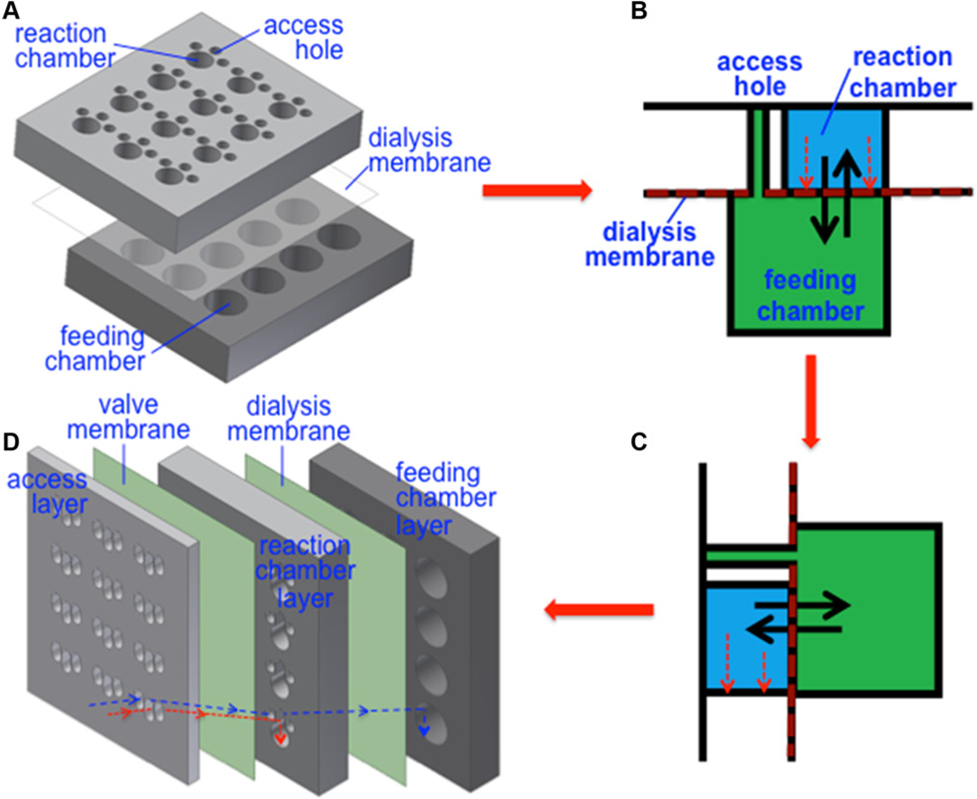
Three devices were fabricated using polycarbonate sheets and dialysis membranes. The first device, referred to as the Horizontal Device, is the same as reported previously. 14 As shown in Figure 1a , it consists of three layers: a reaction chamber layer at the top, a dialysis membrane in the middle, and a feeding chamber layer at the bottom. The top and bottom layers were machined in 0.5 inch thick polycarbonate sheets. An array of 3 × 4 wells was created in the footprint of a 96 well plate; for simplicity (and less waste), we did not make a 12 × 8 array. In the top layer, the largest well is a 4.5 mm diameter reaction chamber with a volume of 79.5 mm3, and it is surrounded by three 2 mm diameter access holes connecting to the feeding chambers. The feeding chambers on the bottom layer are 12 units of 9 mm diameter wells with a depth of 3 mm and a volume of 188.6 mm3; each unit encompasses both reaction chamber and access holes in the top layer. As illustrated in Figure 1b , the dialysis membrane in the middle is to separate the reaction and feeding chambers so that small molecules such as ATP can pass through from the feeding chamber to the reaction chamber, whereas proteins synthesized remain in the reaction chamber. The dialysis membrane at the access hole location was punctured so that the feeding chamber became accessible.
(
The device referred to as the Vertical-I ( Fig. 1d ) was derived from the layout in Figure 1c , which was obtained by rotating the layout in Figure 1b by 90°. In Vertical-I, the dialysis membrane is oriented vertically. It consists of five layers: an access layer at the top (on the left in Fig. 1d ), a valve membrane, a reaction chamber layer in the middle, a dialysis membrane, and a feeding chamber layer at the bottom. The top layer comprises 12 units of three wells that are 2 mm wide and 3.5 mm long. Among those three wells, the well in the center (referred to as reaction access well) provides access to the reaction chamber in the middle layer, and the other two wells (referred to as feeding access well) provide access to the feeding chamber in the bottom layer. The valve membrane is designed to prevent the reaction solution from leaking out as discussed later, and we employed a dialysis membrane for this purpose for fabrication simplicity. In the middle reaction chamber layer, each unit consists of one 4.5 mm diameter reaction chamber with a volume of 79.5 mm3 connecting to an extension chamber of 2 mm wide and 2.5 mm long. This extension chamber aligns with the reaction access well in the top layer and provides a passage that guides the reaction solution downward into the circular reaction area, as illustrated by the red dashed arrow in Figure 1d . Because the valve membrane only at the extension chamber portion is punctured, the reaction solution in the circular reaction portion will not leak out through the access well when the device is oriented vertically for protein synthesis. As a result, this membrane essentially functions as a valve. There are also two 2 mm diameter through-holes in the reaction chamber layer, and they are connected to feeding access wells in the top layer and provide access to the feeding chamber in the bottom layer. The dialysis membrane in Figure 1d separates the reaction and feeding chambers and enables the controlled exchange of nutrients and reaction by-products between the two solutions. The feeding chamber layer is composed of 12 units of 9 mm diameter feeding chambers with a depth of 3 mm and a volume of 188.6 mm3 that align with the reaction chambers. Appropriate areas in both valve and dialysis membranes were punctured to access the feeding chamber at the bottom via the feeding access holes in the top. The top layer was machined in a 0.1 inch thick polycarbonate sheet, and the middle and bottom layers were machined in 0.5 inch thick polycarbonate sheets.
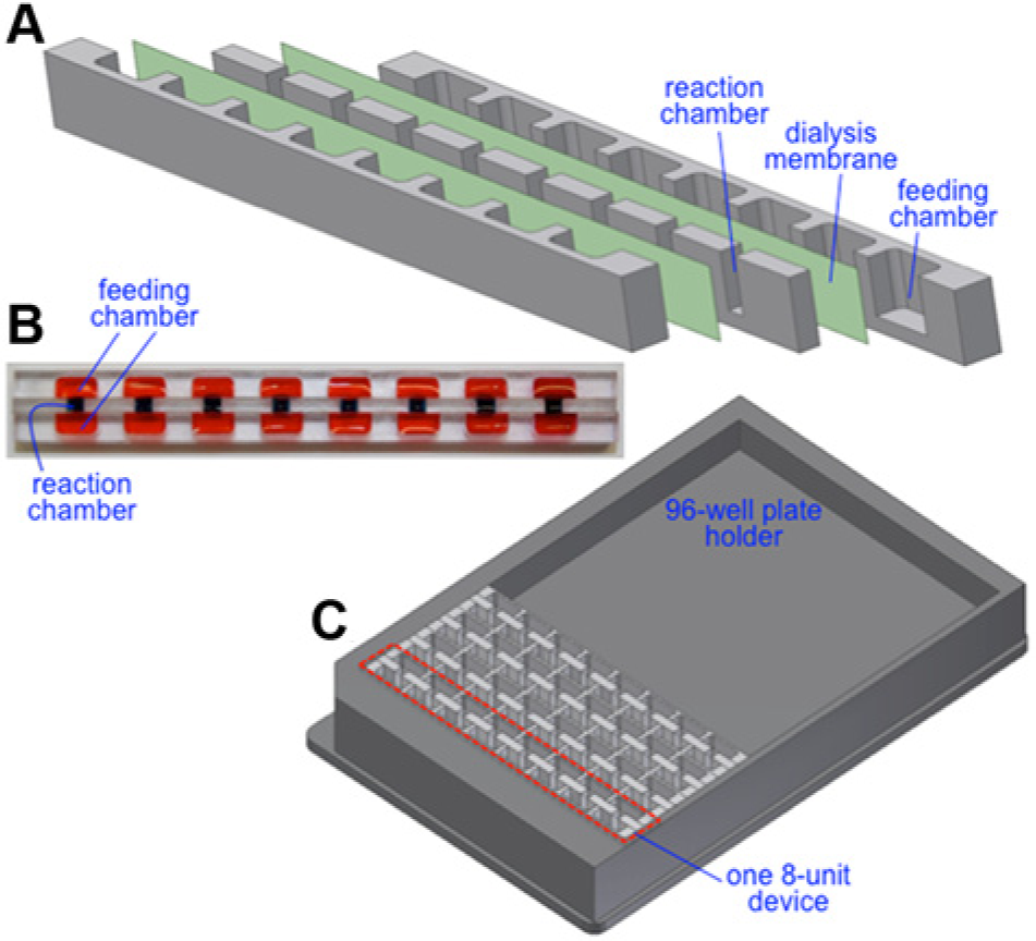
As shown in Figure 2a , Vertical-II also consists of five layers: two feeding chamber layers, a middle reaction chamber layer, and two dialysis membranes. The feeding chamber layers consist of eight units of feeding chambers with dimensions of 7 mm long, 3 mm wide, and 5 mm deep and a volume of 105 mm3 except where specified otherwise. The reaction chamber layer comprises eight units of 2 mm long, 2.5 mm wide, and 5 mm deep reaction chambers with a volume of 50 mm3 that align with the feeding chambers. The location of the reaction chamber is designed according to the standard of a conventional 96 well microplate. The reaction and feeding chambers are separated by two dialysis membranes. The chamber layers were machined in 0.5 inch thick polycarbonate sheets. The design of Vertical-II allows it to serve as 1 of 12 devices that can be placed in a microplate holder for compatibility with a conventional plate reader for detection. An illustration of this microplate holder with four Vertical-II devices is shown in Figure 2c .
(
All devices were assembled using a microstamping technique.14,29 In brief, polydimethylsiloxane (PDMS; Sylgard 184, Dow Corning) was prepared according to the manufacturer’s instructions and coated on a substrate using a spinner (Laurell Technologies, North Wales, PA) at 1500 rpm for 15 s. For each device, the surfaces that interact with the dialysis membrane in the final device were brought into contact with the PDMS on the substrate, transferring a thin layer of PDMS to the polycarbonate surface. The devices were then assembled such that one dialysis membrane separates each polycarbonate layer coated with PDMS. The assembly was then cured in an oven at 70 °C for 4 h and left overnight in room temperature before experiments. A picture of one assembled device is shown in Figure 2b .
Protein Synthesis
The RTS100 wheat germ kit was used to synthesize β-glucuronidase (GUS). All of the components necessary for protein synthesis were included in the kit. Following the manufacturer’s instructions, the reaction solution consists of 15 µL of wheat germ lysate, 15 µL of the reaction mix, 4 µL of amino acids, 1 µL of methionine, and 15 µL of the GUS control vector (2 µg) in nuclease-free water. The feeding solution is composed of 900 µL of the feeding mix, 80 µL of amino acids, and 20 µL of methionine.
For experiments in a device, 10 µL of the reaction solution and 200 µL of feeding solution were pipetted into the reaction and feeding chambers, respectively. GUS expression in the conventional microplate was carried out by pipetting 10 µL of reaction solution into a well of a black 96-well microplate. The devices were covered with PCR tape to prevent evaporation and placed on an orbital shaker at 30 rpm for 4 h, except where specified otherwise. For device optimization, the length of reaction time was varied to determine the optimal reaction time in the vertically oriented devices. To detect GUS expression in the devices, the product was transferred to a black 96-well microplate, and 30 µL of 100 µM MUG was added. The microplate was then placed in the Mithras Microplate Reader (Berthold Technologies, Germany). After 15 min, the fluorescence was measured for 10 s using a filter with excitation and emission wavelengths of 355 nm and 460 nm, respectively.
To study the movement of solutions between the chambers of a device, two experimental setups were designed. In the first setup, 10 µM of fluorescein (Sigma-Aldrich, St. Louis, MO) was included in the reaction solution while the feeding solution was prepared as described above. The reaction and feeding solutions were then pipetted into the reaction and feeding chambers of the device, respectively, and the device was covered with PCR tape and placed on an orbital shaker at 30 rpm for 5 h. After each hour, 2 µL of the feeding solution was removed from the device, and its fluorescein concentration was measured by transferring it to a microplate. To ensure the well bottom of the microplate was covered with a sufficient amount of liquid for measurement accuracy, 10 µL of the pure feeding solution was added before measuring fluorescence. The fluorescence was measured for 10 s using the microplate reader at excitation and emission wavelengths of 485 and 535 nm, respectively. To maintain the solution level and prevent the additional hydrostatic pressure between two chambers, 2 µL of pure feeding solution was added back into the reaction chamber at each hour. All of these dilution effects were compensated in calculating fluorescein concentrations. The second setup had the same experimental conditions as the first setup, except that fluorescein was added to the feeding solution instead of the reaction solution, and 2 µL of the reaction solution was removed each hour for fluorescence measurement.
Results and Discussion
Membrane Orientation
In a device for continuous-exchange CFPS, the dialysis membrane serves to segregate the reaction solution from the feeding solution while simultaneously allowing for the exchange of vital molecules between the two solutions. This separation isolates all of the machinery necessary for DNA transcription and protein translation within the reaction chamber, creating a highly concentrated environment for protein synthesis. As proteins are synthesized, energy and nutrients within the reaction chamber are depleted, and by-products such as inorganic phosphate are accumulated. Without the dialysis membrane, these two conditions would hinder further protein synthesis. With the dialysis membrane, however, small nutrient/energy molecules from the feeding solution can pass into the reaction solution, and the by-products can diffuse from the reaction solution to the feeding solution, thus sustaining protein synthesis.
The dialysis membranes can be oriented either horizontally or vertically within the device. In the horizontal orientation as in Figure 1b , heavy molecules such as protein aggregates or ribosome may settle on the membrane, potentially blocking the membrane pores and thus hampering protein synthesis. By orienting the membranes vertically as in Figure 1c , large molecules would settle against the polycarbonate surface at the bottom of the device, eliminating membrane blockage and increasing protein synthesis yield.
To determine if membrane orientation affects protein expression, Vertical-I ( Fig. 1d ) was designed and fabricated based on the previously reported 14 Horizontal Device ( Fig. 1a ). As conveyed by Figure 1b and c , Vertical-I has similar characteristics to the Horizontal Device with a single feeding chamber and a reaction chamber surrounded by access wells to the feeding chamber. However, Vertical-I consists of five layers instead of three. The two additional layers (the access layer and valve membrane), as well as the passage region in the reaction chamber layer, prevent leakage of fluid out of the device when the device is placed vertically during protein synthesis.
Table 1 illustrates the effect of membrane orientation on GUS synthesis yield. Fluorescence measurement is used to quantify the amount of GUS expressed in various devices. The negative control is the replacement of the GUS vector with nuclease-free water in Vertical-I. In the conventional microplate, the observed protein expression is the result of the minimal amount of nutrients and energy included in the reaction solution used. By including a dialysis membrane for the replenishment of nutrients and removal of by-products, GUS synthesis yield increased 67-fold in the Horizontal Device. The synthesis yield of GUS further increased to 174-fold in Vertical-I. In other words, an increase of 2.6-fold in GUS synthesis yield was obtained by orienting the dialysis membrane vertically.
Comparison of protein synthesis yield in various devices.
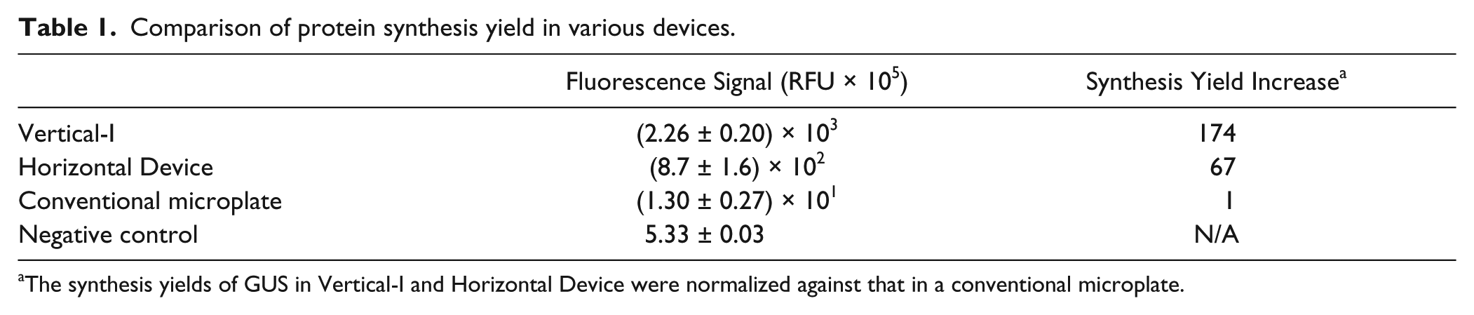
The synthesis yields of GUS in Vertical-I and Horizontal Device were normalized against that in a conventional microplate.
Because Vertical-I was designed to compare the effects of device orientation, fabrication and use of Vertical-I are often a challenge. The device is oriented horizontally when the solutions are dispensed into the chambers, and it must be carefully rotated to be vertically oriented before the reactions take place. When dispensing the reaction solution, the pipet should touch the dialysis membrane so that the solution will not retain on the plastic wall (due to surface tension). At the same time, caution must be exercised to avoid accidental piercing of the membrane. Also, by depositing directly onto the dialysis membrane, most of the reaction solution will remain in contact with the dialysis membrane as a result of surface tension, and it will flow to the bottom of the reaction chamber as a result of gravity after the device rotation.
To avoid these challenges, Vertical-II ( Fig. 2 ) was designed and fabricated. This device has a central reaction chamber with two feeding solution interfaces to provide maximal contact between the reaction and feeding solutions. The device design also allows for expedient deposition of solutions without the necessity of puncturing dialysis membranes. For experiments, the ratio of reaction solution to feeding solution remained 20:1 with 100 µL of feeding solution pipetted into each feeding chamber.
Because optimization is device dependent, both vertically oriented devices were studied with geometry variation and other conditions as discussed below. A comparison between devices was made, and the effects of the vertical orientation of the dialysis membrane on the reaction kinetics were studied.
Hydrostatic Pressure
The chemical exchange between the reaction and feeding solutions occurs as a result of concentration gradients and the subsequent diffusion of solutes in the solutions. To determine if hydrostatic pressure caused by height differences between the feeding and reaction solutions contributed to this exchange in the vertically oriented devices, the height of the reaction chamber was varied in Vertical-II, and the hydrostatic pressure was characterized by the height difference (Δh) between the feeding and reaction solutions. A positive height difference is indicative of a feeding solution level greater than the reaction solution, which corresponds to the movement of solution from the feeding chamber into the reaction chamber. A negative height difference indicates that the feeding solution level is below the reaction solution level and the flow of reaction solution from the reaction chamber to the feeding chamber. A height difference of 0 mm corresponds to equal solution heights, and the flow of solutes between the chambers is attributed to diffusion only. This experiment was not performed in Vertical-I as the height difference between the solutions is difficult to determine because of partial wetting of the membrane when dispensing solutions.
As shown in Figure 3 , hydrostatic pressure effects are present in the system as the measured fluorescence signal increases with an increase in the height difference between the solutions. This trend is in general agreement with the hydrostatic pressure effects previously observed in the Horizontal Device. 19 The greatest protein expression occurs when the height difference between the feeding and reaction solutions is greater than 2 mm. At this height difference, hydrostatic pressure increases the influx of feeding solution into the reaction chamber, supplementing the reaction solution with a greater amount of nutrients and energy for protein expression. For later experiments, the height difference of 3 mm was chosen because this height difference happens to have equal reaction and feeding chamber depths for the geometry we chose for Vertical-II.
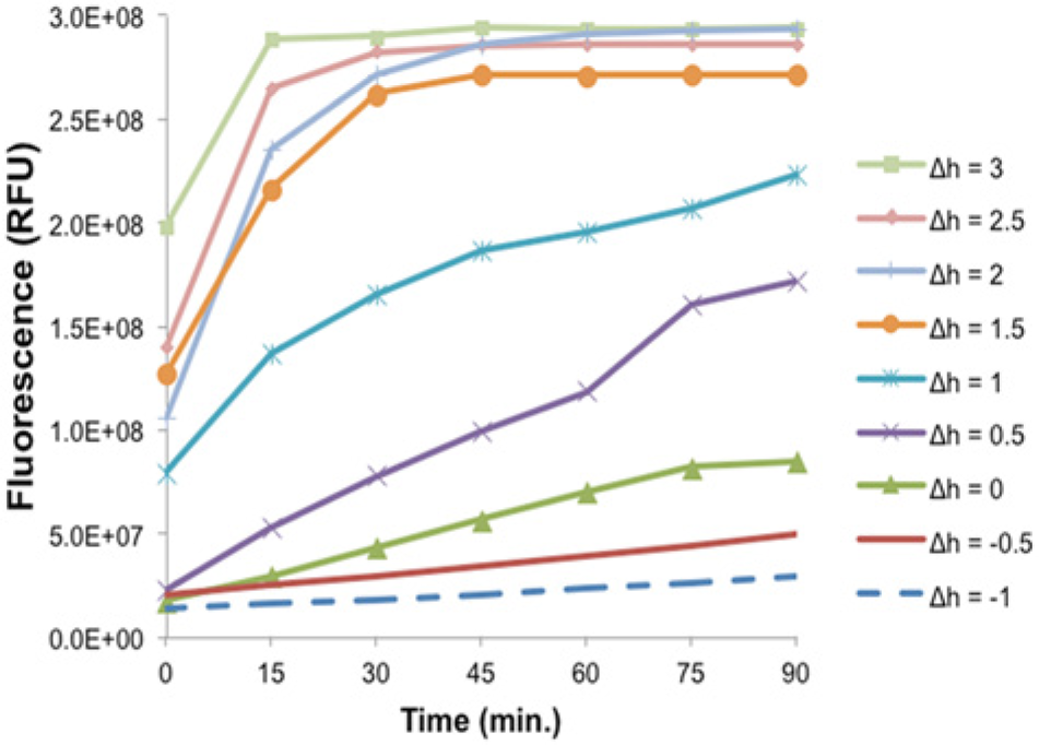
The effect of hydrostatic pressure on protein synthesis in Vertical-II. The Δh value was the height difference between the feeding and reaction solutions and varied between −1 and 3 mm. Devices were fabricated by varying the reaction chamber depth and feeding chamber width. Each data point represents the average of the results from three experiments.
Reaction Time
The time allotted for molecule exchange and protein expression also affects protein synthesis yield because the yield is dependent on both DNA template concentration and experimental timing. 30 Protein expression increases with reaction time until the depletion of nutrients and accumulation of by-products sufficiently slow down reactions. With the dialysis membranes in continuous-exchange CFPS systems, reaction termination is delayed as a result of the controlled exchange of solutes across the dialysis membrane. As a result, protein synthesis yields are greater than batch systems such as in the conventional microplate.
To monitor the reaction time for protein synthesis in the vertically oriented devices, protein synthesis was allowed to occur for 0.5, 1, 1.5, 2, 4, 6, 8, and 10 h before adding the assay reagent (MUG) and measuring the fluorescence signal. The same experiment was conducted in the conventional microplate and Horizontal Device for comparison, and the results are shown in Figure 4 . Protein synthesis yield reached to plateau after 1.5 h in Vertical-II and 2 h in Vertical-I. For the Horizontal Device, protein synthesis yield plateaued after 4 h of reactions. The difference in the reaction times between vertically and horizontally oriented devices is likely attributed to the sedimentation of large molecules (e.g., ribosomes or aggregated proteins) in the reaction solution. With the vertically oriented devices, large molecules may settle at the bottom of the device instead of against the dialysis membrane, allowing molecule exchange to occur efficiently and expediently. In the Horizontal Device, sedimentation likely blocks pores, hindering molecule exchange and prolonging reaction termination.
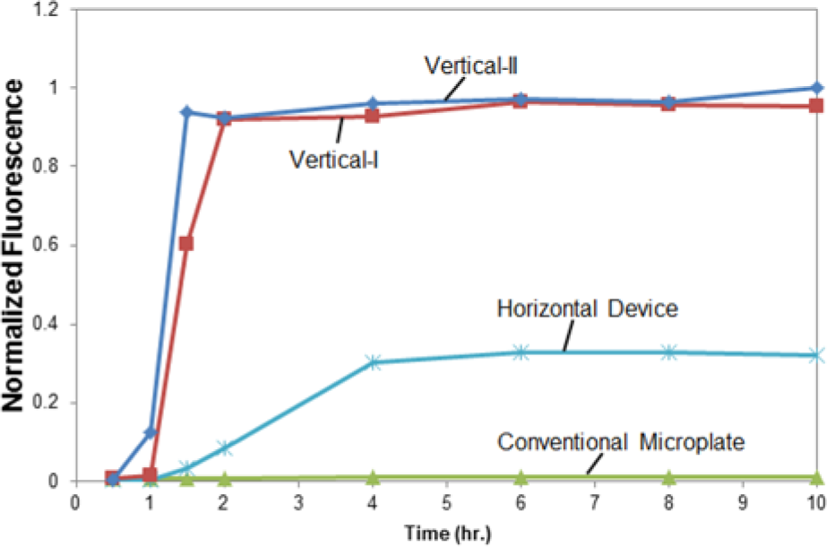
The effect of reaction time on protein synthesis in four types of cell-free protein synthesis devices. Protein expression in each device was permitted for 0.5, 1, 1.5, 2, 4, 6, 8, and 10 h. The protein synthesis yield as quantified by the fluorescence signal is normalized against the highest fluorescent signal.
Diffusion Measurement
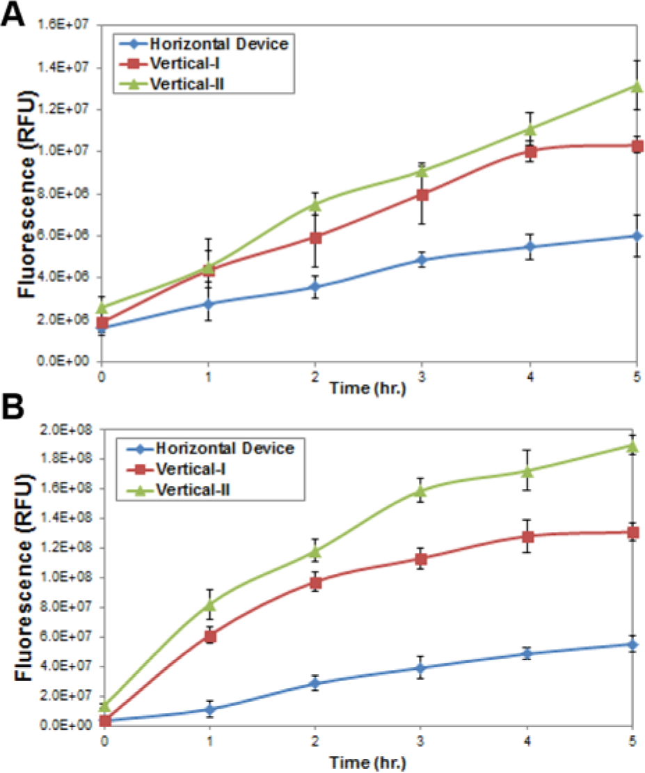
To determine if possible settling of large molecules is occurring in the Horizontal Device and alleviated when the dialysis membrane is oriented vertically, we performed experiments to monitor the diffusion of fluorescein in the Horizontal Device, Vertical-I, and Vertical-II. For monitoring movement of the chemicals from the reaction solution to the feeding solution, the first setup was to add fluorescein in the reaction solution, followed by the measurement. For the chemical movement from the feeding solution to the reaction solution, the second setup with the addition of fluorescein to the feeding solution was used. The results from the first and second setup are depicted in Figure 5a and 5b .
(
The results illustrate the greatest chemical movement from both the reaction and feeding solutions in Vertical-II, followed by Vertical-I and the Horizontal Device. The lowest fluorescence in the Horizontal Device indicates the slowest diffusion through the dialysis membrane, suggesting possible sedimentation of large molecules onto the membrane. Higher fluorescence in the vertically oriented devices suggests the reduction or elimination of such effects. These results explain that the orientation of Vertical-I and Vertical-II resulted in higher protein synthesis yield.
The difference between Figure 5a and 5b is likely attributed to the hydrodynamic pressure as discussed above. The feeding solution level was 3 mm higher than the reaction solution level in both cases; thus, we expect more diffusion of fluorescein from the feeding chamber to the reaction chamber in Figure 5b .
Protein Synthesis
After device geometry optimization and reaction time studies, GUS expression was performed in the conventional microplate, Horizontal Device, Vertical-I, and Vertical-II, and the results are compared in
Figure 6
. Luciferase was also expressed in the conventional microplate, Horizontal Device, Vertical-I, and Vertical-II, and the results are depicted in
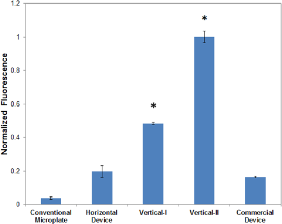
Comparison in β-glucuronidase (GUS) synthesis yield among the conventional microplate, Horizontal Device, Vertical-I, Vertical-II, and commercial RTS100 device. The protein synthesis yield was quantified by the fluorescence signal after adding the assay reagent (4-methylumbelliferyl-β-D-glucuronide). The signals were normalized against the highest signal, and they represent the fluorescence per unit volume and unit interface area between the feeding and reaction chambers. The average of three repeated experiments is plotted, and the error bars indicate one standard deviation. The stars (*) indicate a p value less than 0.05 in a comparison between Vertical-I and Vertical-II with the Horizontal Device.
The commercially available RTS100 kit includes a CECF device with two compartments for the reaction and feeding solutions, and thus we compared it with our devices. In this device, a semipermeable membrane is horizontally oriented. Compared with our miniaturized array devices, the RTS100 system requires five times as much solution as in our devices because the manufacturer’s instructions specify 50 µL of the reaction solution and 1 mL of the feeding solution. To accommodate more reaction solution volume in the commercial device, we used 150 µL of MUG to ensure sufficient assay reagents (compared with using 30 µL for our devices). We should also note that the membrane area in the commercial device is about ~50 mm2, whereas our membrane contact area in Vertical-II is 8 mm2. A larger membrane contact area should lead to more efficient exchange and thus higher protein synthesis yield. Taking into consideration the differences in both volume and the membrane area, Vertical-II increased GUS expression 505% over the commercial device, as shown in Figure 6 . A probability test comparing Vertical-II with the commercial device indicates that there is a statistical difference in protein synthesis yield with a p value less than 0.05, indicating they are statistically different at the 95% confidence level. The results suggest the advantages of our device in the reagent consumption and protein synthesis efficiency.
Conclusion
We investigated the effect of membrane orientation on protein synthesis yield by designing and fabricating two miniaturized continuous-exchange CFPS devices with vertically oriented dialysis membranes. The design of the first device, Vertical-I, is based on the previously designed 14 horizontal-format CFPS device, whereas Vertical-II is a new device with compatibility with commercially available reagent dispensers and microplate readers. With the vertical orientation of the membrane, nanopore clogging is reduced or eliminated because the large molecules settle to the bottom of the device instead of the dialysis membrane, thus improving protein synthesis yield.
The vertically oriented devices were experimentally optimized by studying the effects of hydrostatic pressure and reaction time on protein expression. Our studies indicate that hydrostatic pressure had an impact on protein expression, and the greatest protein synthesis yield occurred when the height difference between the reaction and feeding solutions was maximized. The reaction time for the vertically oriented devices was found to be less than the horizontally oriented device. With membrane clogging reduced in the vertically oriented devices, chemical exchange across the dialysis membrane occurred more efficiently and expediently.
We have demonstrated that protein synthesis yield in the vertically oriented devices is significantly enhanced compared with the horizontal device. Protein expression per unit volume and interaction area between the feeding and reaction solutions in Vertical-I and Vertical-II increased 144% and 406%, respectively, and Vertical-II increased protein expression 505% over the commercial RTS100 device. The judicious design enabled Vertical-II to be compatible with a conventional 96-well microplate while using five times fewer reagents than the commercial RTS100 device. With this compatibility for commercial reagent dispensers and microplate readers, as well as rapid reactions and high synthesis yields, Vertical-II could find potential applications such as high-throughput protein synthesis and drug screening.
Footnotes
Declaration of Conflicting Interests
A provisional patent application has been filed by the authors’ employer, the University of Florida. Covitect Inc. has an option to negotiate a license to the patent rights. The authors declared no other potential conflicts of interest with respect to the research, authorship, and/or publication of this article.
Funding
The authors disclosed receipt of the following financial support for the research, authorship, and/or publication of this article: This work was supported in part by National Science Foundation (OISE-0968313), Defense Advanced Research Projects Agency (DARPA), and the University of Florida.
References
Supplementary Material
Please find the following supplemental material available below.
For Open Access articles published under a Creative Commons License, all supplemental material carries the same license as the article it is associated with.
For non-Open Access articles published, all supplemental material carries a non-exclusive license, and permission requests for re-use of supplemental material or any part of supplemental material shall be sent directly to the copyright owner as specified in the copyright notice associated with the article.