
Abstract
Introduction
Poststroke hemiparesis can significantly limit walking ability and independence by slowing walking speeds, increasing gait asymmetry, and compromising balance.1,2 Individuals with moderate and severe impairment may have gait characterized by a combination of foot-drop, minimal push off, limited knee mobility (stiff-knee), excessive knee flexion in stance (buckling-knee), or a hyperextended knee in stance. 3 This results in difficulty obtaining adequate foot clearance, lower propulsive power, decreased occurrence of initial contact with the heel, reduced range of motion, and limited knee stability.1–6 Many of these gait deficits can be attributed to diminished muscle strength, inappropriately timed and graded muscle activity, and hypertonia.4,5
Powered exoskeletons and neural stimulation have been explored as interventions to improve gait in stroke survivors. Peroneal nerve (foot-drop) stimulators can assist with foot clearance 7 and multi-channel surface stimulation can provide incremental improvements over the basic walking function of individuals with hemiparesis. 8 Limitations of surface stimulation include day-to-day variability, fatigue, and inconvenience of donning, doffing, and cutaneous sensation. 9 Additionally, muscles such as the short head of biceps femoris can be challenging to selectively recruit from the skin surface making knee flexion and foot clearance difficult to achieve reliably in stroke survivors with more moderate or severe impairment. Powered exoskeletons with bilateral actuators at the hips and knee have primarily been used as therapeutic tools rather than as assistive devices to facilitate for daily ambulatory function because of their size and the necessity for stand-by assistance.10–12 These systems may be too large for a stroke survivor to use on a daily basis. Hybrid exoskeletons that combine neural stimulation and exoskeletal assistance have been applied for therapeutic purposes,13–23 but could also hold potential as assistive devices during daily walking. This combination offers a solution to the limitations of each intervention, where neural stimulation engages muscles and reduces demand on the motors to allow for smaller actuators,18,22,24 and the motors can provide reliable and consistent assistance for difficult to recruit muscles/movements.
Based on the hybrid approach and an implementation strategy of driving movement via combined volitional effort and neural stimulation augmented by motors as needed, we developed a hybrid exoskeleton combining multi-channel surface stimulation and an exoskeletal knee brace. Neural stimulation targeted muscles crossing the hip, knee, and ankle; however, some muscles are easier to recruit and more likely to have a strong and isolated response from electric currents applied to the skin surface. 9 The addition of a motor at the knee can add the flexion or extension torques during swing to ensure adequate foot clearance and prepare for initial contact and weight acceptance. In stance the motor assists knee stability by applying torque to prevent excessive flexion or hyperextension. Effectively combining these approaches requires that the actuator (i.e., motor and transmission) moves easily when muscles generate functional motions instead of resisting movement. 25 One approach is through maximizing backdrivability so contracting muscles can overcome the system’s friction and inertia to move the joint. 24
We developed a prototype system that combined stimulation and exoskeletal approaches and evaluated critical features for a hybrid exoskeleton to facilitate ambulation after hemiparesis. We assessed proof-of-concept in a stroke survivor to determine whether: (1) the motor and transmission are sufficiently backdrivable such that stimulation-generated muscle contractions can still produce useful movements; (2) the actuator is capable of producing movement independently, and (3) the combination of stimulation and actuator generate beneficial kinematic changes exceeding that of stimulation or motor assistance individually.
Methods
The hybrid exoskeleton (Figure 1) is a unilateral lower limb assistive device designed for walking after hemiparesis. It combines an electromechanical actuator with rotation axis parallel to the approximate rotation axis of the knee (see Electro-mechanical actuator) with neural stimulation (NS) to activate muscle groups in the thigh and shank (see Neural stimulation). Orthotic elements integrated the system to enable adjustments to fit each user’s unique anthropometric dimensions (see Orthotic components). Neural stimulation generated contractions targeting muscles acting at the hip, knee, and ankle, while the knee actuator provided additional assistance to enhance swing phase foot clearance, prepare for initial contact, and prevent buckling in stance. Integrated sensors (see Device electronics) informed an onboard controller to transition between gait phases and required levels of assistance for each state (see Controller). User wearing the hybrid exoskeleton.
Electro-mechanical actuator
Actuator modifications.


Section view of knee actuator. Blue arrows indicate modification identified in Table 1.
Actuator specifications.

Neural stimulation (NS)
NS activated the user’s muscles through surface electrodes adhered to the skin. Electrodes were not affixed to the exoskeleton, they were placed manually based on the individual’s responses to stimulation. A custom 8-channel control unit delivered charge balanced bipolar stimulation to as many as 8 pairs of electrodes. Target muscles can be selected based on specific user needs; muscles for our test pilot are presented in the Participant section. The maximum amplitude, pulse width, and frequency were 100 mA, 255 µs, and 50 Hz, respectively, with specific values chosen based on user tolerance and adequate contractile response. Stimulation parameters could be varied in real-time on a pulse-by-pulse basis in increments of 1 mA and 1 µs. A physical therapist adjusted values of these parameters for each muscle to prioritize the self-reported comfort while generating functional movement. Strong contractions that were not painful were elicited from each muscle, but the stimulus parameters were not optimized. Commonly targeted muscles might include quadriceps, hamstrings, gastrocnemius, tibialis anterior, and gluteus maximus. These muscles typically address issues such as foot-drop, knee range of motion limitations, and lack of propulsive power that stroke survivors often exhibit. Additional muscles such as tensor fasciae latae, gracilis, and sartorius might also be targeted, but may be more challenging to recruit, or be uncomfortable to the user.
Orthotic components
Alignment between user and exoskeleton is paramount for optimal comfort and movement efficiency. Misalignment has been identified as one of the most common complications associated with exoskeletons. The primary factors contributing to misalignment include: (1) soft tissue interface design (material, stiffness, quantity and size of attachment points, (2) incorrect positioning, and (3) oversimplified kinematic structure. 31 Our custom-designed hybrid exoskeleton accommodates the user through adjustable components that enable translations in the anterior/posterior (A/P), proximal/distal (P/D), and medial/lateral (M/L) directions. These adjustable components enabled positioning attachment points, such as a thigh and shank cuff, centered and flush against the user’s leg, while aligning the exoskeletal knee actuator with the anatomical knee center to efficiently transmit assistive torques to the user.
The exoskeleton was attached to the pilot via a thigh cuff, shank cuff, and footplate (Figure 3). The thigh cuff (Newport 3, Orthomerica Products, Inc.) was positioned on the anterior thigh and connected to the actuator via a T-shaped bracket, which facilitated adjustments in the P/D and A/P directions (Figure 3(a)). This adjustable placement along the thigh avoids groin impingement and aligns the actuator with the midline of the thigh. Adjustments in the P/D and A/P directions could be made in 13.97 mm [0.55 in] and 16.64 mm [0.655 in] increments, covering a total range of 83.82 mm [3.3 in] and 66.55 mm [2.62 in], respectively. The P/D increment size aligned with the original bolt pattern of the off-the-shelf part, with the diameter of the bolt head serving as the limiting factor. The A/P increment size was restricted by a load cell (see Device electronics) serving as an interface between the cuff and the actuator. A 3D printed nylon shank cuff padded with Tempor Foam® was connected to the actuator through a series of slides and brackets allowing adjustments in the P/D, A/P, and M/L directions (Figure 3(b)). These adjustments facilitate comfortable positioning below the knee, centering along the shank’s midline, and flush against the shin. Adjustments in the P/D and A/P directions could be made in discrete increments of 25.4 mm [1 in] and 4.763 mm [0.188 in] over total ranges of 76.2 mm [3 in] and 85.725 mm [3.375 in], respectively, while M/L adjustments were continuous over a 101.6 mm [4 in] range. These sizes and ranges were determined through iterative design and testing of multiple prototypes on different users. The footplate, consisting of PolyCar-C™ (Fillauer®), a rigid carbon fiber prepreg, was molded to fit around the heel and extend to the midfoot. A J-Turf (JMS Plastics Supply®) carbon fiber insole was placed inside the PolyCar-C™ foot shell. On top of the carbon fiber insole a sheet of Op-Tek® Flex (Curbell Plastics, Inc.), a soft, flexible EVA (Ethylene Vinyl Acetate) Copolymer, was formed inside the rigid shell, extending slightly distal to the malleoli and extending the length of the foot. A layer of puff padding (EVA 35 shore A, Acor Orthopedics®.) was adhered to the inside for additional comfort. This construction allowed bending at the forefoot to avoid interfering with the propulsive power from push off (Figure 3(d)). A stainless-steel stirrup (Becker Orthopedic) with an unactuated rotary ankle joint was fastened with rivets on the lateral side of the foot shell. The user’s paretic foot was secured to the footplate by a hook and loop strap. The ankle joint stirrup was fastened via thumbscrews inside a channel on the upright extending from the output arm of the actuator and could be adjusted in the P/D direction (Figure 3(c)) in increments of 12.7 mm [0.5 in], spanning a total range of 127 mm [5 in]. This adjustment allows the output center of the knee actuator to be raised or lowered to coincide with the knee joint. (a) Thigh cuff, (b) shank cuff, and (c) shank upright with their adjustment directions indicated by red solid arrows for anterior-posterior (A/P), green dashed arrows for proximal-distal (P/D), and blue dotted arrows for medial-lateral (M/L) adjustments, (d) Bottom view of the footplate with a red square representing its flexible forefoot.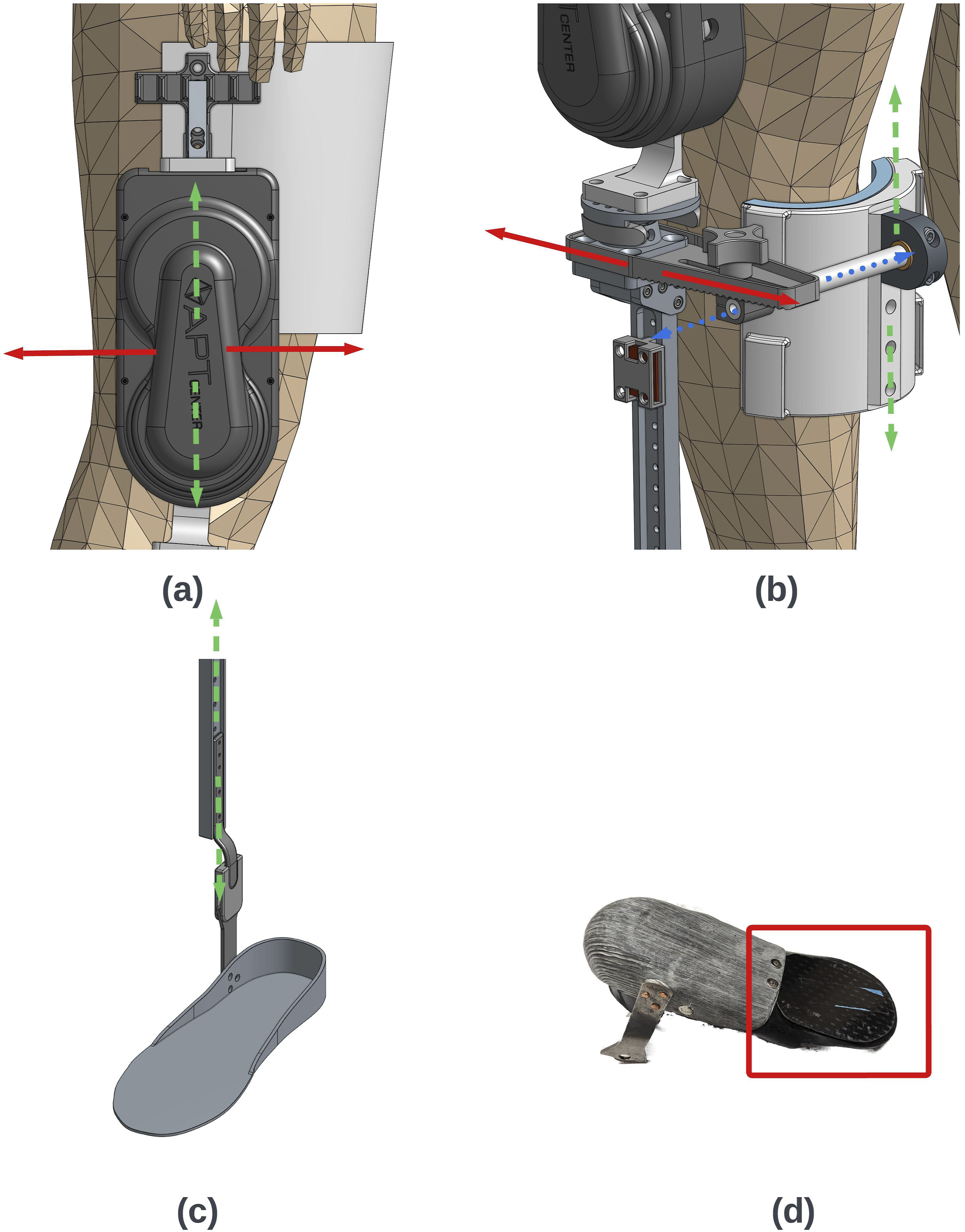
When donning the exoskeleton, the fitment is performed from the ground up with the user sitting down. First, the foot is positioned inside the footplate and secured with the hook and loop strap. Proper fitment was assessed by checking for excessive (>∼12.7 mm [0.5 in]) length mismatch between the end of the foot and footplate. Upon inspection the foot/footplate combination is inserted into the shoe (usually sized up one-half size to accommodate the added bulk of the footplate). Next, the ankle joint stirrup is positioned in the channel of the shank upright (extending from the output arm of the actuator) to a height aligning the output center of the knee actuator with the user’s anatomical knee center. Afterwards, the shank cuff is inserted into the slide and bracket on the upright, adjusted to align centered and flush with the shin, and then secured around the back of the calf with hoop and loop straps. Following this, the knee actuator, along with the attached thigh cuff, is rotated down around the user’s thigh and secured with hook and loop straps. The user is then instructed to stand up, with assistance from the physical therapist, if necessary, to check for groin impingement from the thigh cuff and alignment of the actuator and upright with the coronal plane.
Device electronics
Sensors were distributed throughout the hybrid exoskeleton to measure paretic limb motion, ground contact, motor speed, and current, as feedback signals for control. Sensors for motion included two IMUs (part no. SEN-14686, SparkFun) mounted on the exoskeleton at the thigh and shank to measure orientation, angular velocity, and angular acceleration of the respective segments. A potentiometer (part no. RH24PC E R10K L2% D5 110 mm, P3 America) tracked knee joint angle and was attached to the actuator’s output via a D-shaft. A load cell (part no. SEN-13329, SparkFun) measured interaction forces at the thigh, connected between the actuator and the thigh cuff.
An insole comprised of eight force sensitive resistors (FSR) (part no. 01-006893-00-10, IEE) in each shoe sensed when the toe and heel were in contact with the ground. These signals, in combination with the IMUs, detected transitions between gait phases. Three hall effect sensors integrated with the motor measured its speed.
Signals from each sensor were fed into a propulsion module consisting of two microcontrollers (MCU) (Teensy 3.6, PJRC), the motor controller (Maxon Motors 438725), and other signal processing circuitry (Figure 4). One MCU served as the primary MCU (PM) that handled data processing, controller logic, and sending current commands to the motor controller and stimulation parameters to the external stimulator. The second MCU functioned as a recording MCU (RM) to save specified parameters and output data received from the PM to a micro-SD card. The two MCUs communicated via UART serial communication. The PM converted analog signals from the potentiometer and load cell using integrated analog-to-digital converters on the Teensy 3.6. The IMUs had their own dedicated Teensy 3.6 MCU that sampled data using UART serial communication and then transmitted data to the PM using controller area network (CAN) bus communication. Signals from the FSR under the less affected foot were sent wirelessly to the PM via a pair of wireless transceivers, while the FSR under the paretic foot was hardwired to the PM. The wireless transceiver on the PM side also received signals from a wireless finger switch to initiate a calibration cycle or initiate/terminate walking assistance. The PM sampled all incoming signals and sent stimulus and motor commands at 100 Hz. The electronic board was powered with a 28.8 V battery (part no. PH3059HD25, Inspired Energy). Sensor and electronics flowchart.
Controller
For proof of concept, the exoskeleton was controlled by a feedforward finite state machine (FSM) divided into four states based on the gait cycle: early swing, late swing, early stance, and push off (see Figure 5). State transitions were determined from the thigh and shank orientations and velocities as measured from the IMUs, as well as initial contact and foot off events from the FSRs. NS was applied to muscles known to elicit desired motions in each given state. (Upper) The four gait phases that comprise the finite state machine. (Lower) Targeted muscles and motor assistance applied for each phase.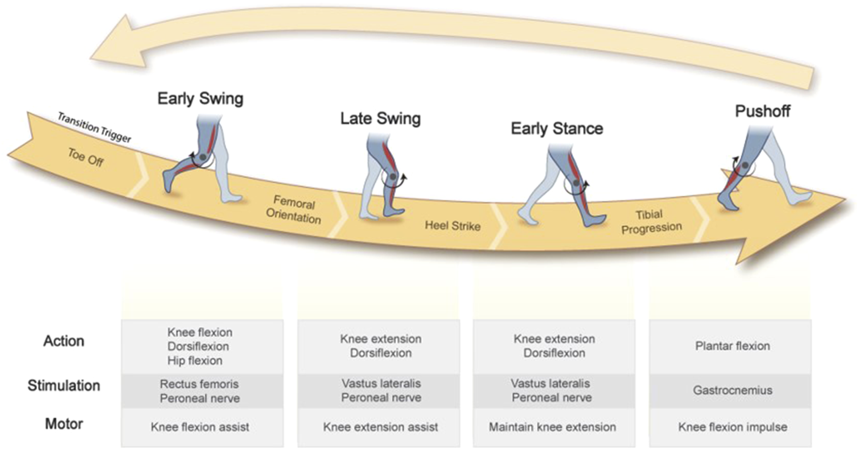
Controller parameters for our participant.

aRange of values based on polynomial fit as a function of knee angle.
Participant
The system was evaluated on a single stroke survivor to verify that the hybrid approach works in conjunction with an individual with hemiparesis. The participant provided written consent under the Louis Stokes Cleveland Veterans Affairs Medical Center institutional review board (IRB) (ref:19020-H09). The participant presented with left side hemiparesis manifesting in foot-drop, low propulsive power, limited knee motion in swing, initial contact with the toes, and knee instability in stance. The participant was a household ambulator, walked with a tripod cane, and used a small elastic ankle foot orthosis (AFO) connecting the shank and top of the shoe to limit foot-drop. The participant’s stroke occurred 4.5 years prior to enrolling in the study and they were 52 years old at time of testing. Stimulation was applied to tibialis anterior for dorsiflexion during swing, gastrocnemius for plantar flexion for push off into the swing phase, and quadriceps for knee extension to prepare the leg for weight acceptance at initial contact. Hamstrings were not activated with stimulation because it generated a painful sensation prior to eliciting a muscle contraction. Stimulation parameters were determined at the beginning of each session (see Neural stimulation).
Device evaluation
Outcome measures for assessing the device consisted of kinematics collected from overground walks under the following four conditions: 1. Without the device (ND) (Participant walked with his elastic AFO in this condition)
1
. 2. Stimulation only while wearing the exoskeleton (S). 3. Motor assistance only (M). 4. Hybrid assistance combining both stimulation and motor assistance (H).
Number of steps collected for each walking condition.

Prior to outcome assessments the participant completed six gait training sessions with the system to acclimate to walking with exoskeletal and stimulated assistance. Training sessions involved overground walks based on the participant’s endurance as judged by the participant themselves and the accompanying physical therapist. The participant averaged 5.5 walks per training session with an average distance of 172 m [565 ft] with the shortest walk being 64 m [210 ft] and the longest 479 m [1572 ft]. Between walks the participant rested for at least 2 minutes. The goals of the assessments were to verify that stimulation and volitional effort could generate functional movements even in the presence of the system’s passive resistance (S), that the motor could augment walking motions even without stimulation (M), and that the two assistance methods could be coordinated together (H). H condition implemented the same parameters for the motor and stimulator as the M and S conditions. Although the motor parameters are the same, the torques generated in conditions H and M differ since the values are based on angular position and velocity, which changed with the addition of stimulation. The without-device condition served as a control to evaluate the impact of the hybrid exoskeleton against the other conditions.
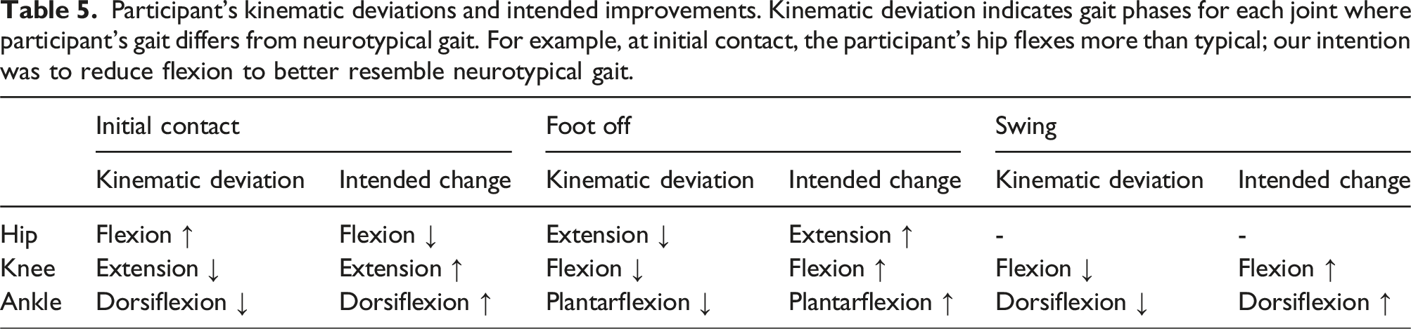
Participant’s kinematic deviations and intended improvements. Kinematic deviation indicates gait phases for each joint where participant’s gait differs from neurotypical gait. For example, at initial contact, the participant’s hip flexes more than typical; our intention was to reduce flexion to better resemble neurotypical gait.
Data processing & statistical analysis
Data were post-processed using Vicon Nexus (Vicon, Oxford Metrics, UK) to label and gap fill marker trajectories and identify initial contact and foot off gait events. Marker trajectories were then exported to MATLAB (Mathworks, Natick, MA, USA) and low pass filtered with a 2nd order Butterworth filter at 6 Hz to eliminate noise, which was found to contain 99.7% of the signal power during walking. 32 Sagittal plane joint angles for the hip, knee, and ankle were calculated based on the filtered marker trajectories. Using identified foot off and initial contact gait events, angles were separated into strides from initial contact to initial contact of the paretic leg and time normalized to 100% of the gait cycle. Conditions were averaged at each time point across the stride. For all joint angles at initial contact and foot off, as well as peak knee flexion and ankle dorsiflexion during swing, we used MATLAB to calculate 95% confidence intervals of their means.
Results
Significant changes were seen at initial contact, foot off and during swing for the hip, knee and ankle angles for most assisted conditions (S, M, and H) compared to no device, except for hip flexion at initial contact (no significant change for S) and knee flexion at foot off (no significant change for M) (Figure 6 and Table 6). Figure 6 shows the ensemble averaged hip, knee, and ankle joint angles for each walking condition. The vertical solid line in each plot represents the mean location of foot off with the dashed lines representing one standard deviation from the mean. Mean difference values between the assisted conditions (S, M, and H) and no device (ND) are shown in Table 6. Except for knee flexion and ankle plantarflexion at foot off, the changes seen are moving towards neurotypical kinematics corresponding with our intended changes in Table 5. The largest changes occurred in the knee and ankle at initial contact, while the smallest changes occurred at the peak knee angle during swing and the hip at initial contact (Table 6). Hip, knee, and ankle joint angles for (a) no device (ND), (b) stim only (S), (c) motor only (M), and (d) hybrid (H) walking conditions. Solid lines represent the mean angle while gray shading represents ±1 standard deviation. Solid vertical lines represent mean location of foot off with the dashed vertical lines representing ±1 standard deviation. Mean differences between assisted walking conditions (S, M, and H) and no device (ND).

Hip-knee cyclograms of the paretic leg, as well as the perimeter and area for each condition, are displayed in Figure 7. The shape of the cyclogram and the perimeter and area can indicate kinematic changes in gait. Larger perimeter and area values are generally associated with more neurotypical gait while smaller values correlate with greater impairment.
36
The S condition shows an increase in perimeter (12.5°) and an increase in area (730.4°2) compared to ND. The M condition shows an increase in perimeter (21.9°) and an increase in area (575.1°2) compared to ND. The H condition shows an increase in area (240.3°2) compared to ND while the perimeter is within two degrees. The increases in perimeter and area seen in each assistive condition brings our participant closer to neurotypical values. Out of the three assistive conditions, the shape of condition H most closely resembles the shape for neurotypical walking. Hip–knee cyclograms, moving clockwise for (a) no device (ND), (b) stim only (S), (c) motor only (M), and (d) hybrid (H) walking conditions. The solid lines represent stance phase, beginning at the black diamond dashed lines represent swing phase, beginning at the black star. The black circle represents the point where the foot crosses immediately under the pelvis.
Figure 8 shows the 95% confidence intervals for the joint angle means at initial contact and foot off as well as peak knee flexion and ankle dorsiflexion angles during swing. These instances within a stride highlight important aspects of gait where gait deficits may limit movement. Six out of the eight kinematic outcomes highlighted in Figure 8 improved while walking with the system (S, M, or H), compared to no device (ND). The two kinematic areas that did not improve towards neurotypical gait were knee flexion and ankle plantarflexion at foot off. 95% confidence intervals for the joint angle means at initial contact (IC), foot off, and peak values during swing for the hip, knee, and ankle for each condition.
Discussion
This report presented the design and initial demonstration of the feasibility of a hybrid exoskeleton combining multi-channel surface stimulation and exoskeletal motor assistance at the knee to enhance walking after stroke. Neural stimulation improved kinematics even with the motor turned off, and the motor was able to drive movement in conjunction with volitional effort without stimulation. More importantly, the two approaches combined were able to assist movement more effectively than either intervention alone.
Neural stimulation with a passive exoskeleton
Wearing the exoskeleton with neural stimulation as the only assistance elicited kinematic changes in the intended direction (see Table 5) at initial contact for all joints, at foot off for the hip, and during swing for the knee and ankle joints compared to without the device. Similar motions have been observed in other studies when targeting the same muscles (tibialis anterior, gastrocnemius, and quadriceps) with NS.37–39 The changes suggest improvement to foot clearance (increased knee flexion during swing), prevention of foot-drop (increased ankle dorsiflexion during swing), and increased step length with more consistent initial contact with the heel (increased knee extension and ankle dorsiflexion and decreased hip flexion). This suggests that even with the increased mass from the exoskeleton and friction from the exoskeletal knee actuator, neural stimulation can generate useful movements. However, knee flexion is reduced at foot off, which was not intended. The knee was observed to hyper extend during stance phase (Figure 6(b)) despite the presence of the brace, which could have contributed to this observation. One possible explanation for hyperextension may be the inertia from the knee actuator causing the knee to move backwards during weight acceptance following initial contact. With the motor active, the controller applied a flexion torque to prevent knee hyperextension, which may be why it was not observed during conditions with motorized assistance (M & H). A second possibility may be that the NS on the quadriceps was too high, causing the hyperextension. However, when setting the stimulation parameters and testing the participant’s response, we did not observe hyperextension which would suggest that stimulation did not induce hyperextension.
Motor only
With motor assistance only, changes relative to ND seen in Figure 8 occurred in the intended direction (see Table 5) towards nominal gait except for knee flexion and ankle plantarflexion at foot off, where the joint angles were relatively unchanged and increased, respectively. This shows the motor worked well in conjunction with the user’s volitional effort. It’s worth noting that motor assistance achieved its primary objectives of increasing swing phase knee flexion (mean difference of 7.1°), increasing knee extension in preparation for initial contact (mean difference of 12.2°), and providing knee stability during stance (reduced flexion in stance without hyperextending, Figure 6(c)). Interestingly, the motor and orthotics had secondary benefits at the hip and ankle even though it only directly assisted knee motion.
When our exoskeleton is used purely as a motorized power assist orthosis, the trends seen in the knee angle throughout gait align with findings from other groups. These findings include Fernández et al. and their ABLE-KS knee exoskeleton, which saw increases in peak knee flexion during swing and prevention of hyperextension during stance with powered assistance vs no exoskeleton conditions. 40 Another study by Puyuelo-Quintana et al. evaluated the Marsi Active Knee (MAK) lower limb exoskeleton. 41 While they did not report results of the knee angle kinematics without wearing the MAK, they did compare the kinematics of users wearing the MAK in a zero force control mode, that is transparent mode, vs active assistance modes. Compared to the transparent mode, the MAK provided improved knee flexion angles when using their continuous assistance mode. The majority of other studies involving robotic assistance, particularly at the knee, for the stroke population either evaluate the device for its therapeutic effects when used as a training aid and/or compared to other conventional therapies.10,11,42–44 For the purposes of this study, which looks to assess, as a proof-of-concept, the potential of our exoskeleton as an assistive device for overground walking, comparisons with therapeutic effects are less relevant.
Hybrid assistance
When using the hybrid exoskeleton with NS and motor assistance combined, the participant showed differences from their regular gait for all areas in Figure 8. Similar to the stimulation only condition, hybrid assistance improved kinematics for all areas except knee flexion and ankle plantarflexion at foot off. The combination of NS and motor generated a greater angular improvement in the target direction, than each type of individual assistance for knee extension at initial contact. The improvement in knee extension suggests that the superposition of body (quadriceps) and exoskeleton generated torques at the knee caused this effect. However, for other areas, the impact of the hybrid assistance fell somewhere between each type of individual assistance and/or was not significantly different. For example, the hybrid assistance resulted in less peak knee flexion compared to condition M and less dorsiflexion at initial contact compared to condition S. This suggests coordination between the two types of assistance can be further improved. There were not any areas where hybrid assistance resulted in a significant unintended kinematic change greater than those found for both types of individual assistance, M & S. This suggests that hybrid assistance may not compound the unintended effects of each portion of combined assistance. While the system did not fully restore normative walking kinematics, the ∼19° improvements in knee extension at initial contact can prevent buckling and improve stability and step length while the ∼18° increases in dorsiflexion at initial contact can prevent toe catches.
To the author’s knowledge there are no other lower limb hybrid exoskeletons combining NS with an exoskeletal knee targeted for the stroke population. The only other lower limb hybrid exoskeleton for stroke found was a letter to the editor by Kobravi et al. for a hybrid exoskeleton using a motorized ankle joint. 45 However, the publication does not present any kinematic changes and instead reports on changes in three clinical tests including functional ambulation category (FAC), Fugl Meyer Assessment Lower Extremity (FMA-LE), and mini balance evaluation system test (Mini-BESTest). While not representing the same population, there have been other studies on hybrid exoskeletons for users with spinal cord injuries (SCI). One study with incomplete SCI participants 46 and another with complete SCI participants 22 show that NS and motor assistance can be combined in overground walking to achieve target outcomes such as a desired knee angle during swing.
Hip-knee cyclograms
Neurotypical, mild stroke, and moderate stroke values for hip-knee cyclograms from. 36

Direct vs indirect assistance
Based on the muscles targeted for stimulation and the actuator at the knee, we directly influenced the following motions: knee flexion via the motor, knee extension through the motor and quadriceps stimulation, ankle dorsiflexion via stimulation to tibialis anterior, and plantar flexion from gastrocnemius stimulation. The hip joint was not directly targeted, but the previously described assistance also improved gait via reduced hip flexion during swing and further decreased hip extension in terminal stance as shown in Figures 6 and 8. Reduced hip flexion may be due to increased knee extension enabling a comparable or longer step without flexing the hip as much. Additional hip extension may be a result of improved knee stability provided by the motor, and/or the assistance from gastrocnemius. As noted earlier, during the motor only walking condition, ankle dorsiflexion increased despite not being directly assisted by the motor or NS. These changes may be due to footplate bracing and its connection to the shank upright. While the connection is an unlocked rotary joint, friction between the mating parts or misalignment between the rotary joint and actual ankle center could add resistance. The resistance may have mechanically influenced the ankle toward a more neutral position during swing.
Limitations and future work
This proof-of-concept demonstration indicates that a hybrid approach could be an effective means to facilitate nominal walking kinematics which could aid impaired aspects of hemiplegic gait such as foot clearance, stability, and walking speed for a single stroke survivor. This project did not implement controller approaches that optimize concurrent neural stimulation and motor assistance.51–53 Future studies should incorporate more optimized controller configurations and examine the robustness and generalizability of these impacts on a larger cohort, and determine which segments of this heterogeneous population may benefit best from the hybrid approach. The modularity of the system should allow it to be tailored to the specific needs of a wide variety of gait difficulties manifested in individuals with hemiplegia, depending on their impairments.
A limited number of data points were collected due to schedule constraints which prohibited more repetitions for some conditions. Additional sessions would allow for more nuanced comparisons of combinations of stimulation and motor assistance as well as enhanced statistical power.
While joint angle trajectories are a common outcome measure to assess walking ability, they do not fully capture the impact of an intervention on mobility. Future studies should incorporate more complete outcomes including walking speed, kinetics, muscle activity, metabolic cost, spatiotemporal parameters, and symmetry of gait. Furthermore, subjective perceptions of the quality of gait and usability of the intervention would be critical to refining the design and application of a hybrid assist system, which will ultimately help elucidate factors important for successful clinical translation and user acceptance.
Electrodes were applied manually during this project. While this facilitated the target response and flexibility in the choice of targets, it contributes to set up time. Furthermore, some target locations could be difficult for a stroke survivor to reach for independent donning. In the future, an array of electrodes integrated directly into the cuffs of the exoskeleton could serve to simplify setup. 54
While the hybrid exoskeleton in this study is an initial prototype, it still highlighted the potential for hybrid assistance within the stroke population. Lighter, more backdrivable exoskeletons have the potential to see increased benefit from neural stimulation due to improved transparency. It is worth noting that the controller in this study was not optimized and could be implemented in other ways. The feedforward finite state machine controller currently serves as a starting point for proof of concept of hybrid assistance in our unilateral device. For ease of implementation, preprogramed neural stimulation and motor impedance control were chosen as a starting point. While these control approaches have been used in other robotic gait rehabilitation projects,55–57 none have demonstrated them in a unilateral hybrid exoskeleton targeting stroke survivors in overground walking. Despite employing a simple feedforward finite state machine, which limits the ability to adapt to changing needs, hybrid assistance was beneficial. Future research directions for rehabilitation robotics including implementation of feedback control involving machine learning and more precise detection of human intention, could aid in the synchronization of stimulation and motor assistance resulting in improved performance.58,59
Conclusions
This project describes the design and initial proof-of-concept of a unilateral hybrid exoskeleton combining neural stimulation and an exoskeletal powered knee to enhance walking for stroke survivors. Neural stimulation and motor assistance individually improved gait towards nominal hip, knee, and ankle kinematics at initial contact, and foot off and during swing. Knee extension at initial contact saw greater kinematic change in the intended direction when using the hybrid combination of motorized and stimulated assistance than each applied individually. This showcases the potential of the hybrid approach to improving poststroke gait beyond those attainable as a rehabilitative tool.
Footnotes
Acknowledgements
We would like to thank Kevin Marcus and Mark Simmons from the Louis Stokes VA Medical Center Prosthetics Department for their assistance in design and acquisition of supplies related to participate fitment. We would also like to thank Maura Malenchek for her assistance during experiments with set up of neural stimulation and contact guarding of the participant. We would also like to thank Hailey Heidecker, Justin Golabek, and Hala Osman for technical assistance and support with data collection.
Author Contributions
NM and RT researched literature and conceived the study. NM, LL, BB, and SS were involved in protocol development, gaining ethical approval, and patient recruitment. Mechanical design, manufacturing, and maintenance were done by MF and BB. MF, NM, SH, and LL were involved in data collection. MF, SH, and NM were responsible for data and statistical analysis. MF wrote the first draft of the manuscript. All authors reviewed and edited the manuscript and approved the final version of the manuscript.
Declaration of conflicting interests
The author(s) declared no potential conflicts of interest with respect to the research, authorship, and/or publication of this article.
Funding
The authors disclosed receipt of the following financial support for the research, authorship, and/or publication of this article: This work was supported by VA RR&D Merit Review (I01RX-003056-01).
Guarantor
NM.