
Abstract
The evaluation of wheelchair cushion performance is of interest to a variety of stakeholders, including standards organizations, cushion manufacturers, clinicians, users and payers. The objective of this project was to develop a family of compliant buttock models that are based upon the anatomical parameters of persons with varying body sizes. The models are parametrically designed so can be scaled to evaluate different sized cushions. This paper will detail the designs, describe the anatomical basis for the design and provide the rationale for the design decisions. The manuscript also serves a secondary purpose to illustrate how anthropometric data can be applied to the design of anatomical phantoms that reflect both soft tissue and skeletal anthropometry. Supplemental material includes greater detail and the full CAD files and model fabrication instructions are available in an open access repository for persons who wish to fabricate the models.
Introduction
The evaluation of wheelchair cushion performance is of interest to a variety of stakeholders. Standards organizations that develop and publish test methods to report varying constructs of performance. Cushion manufacturers are interested in benchmarking their product prototypes during development. Clinicians and users benefit from understanding the span of cushion performance as a means to match a cushion to a user’s needs. And payers may be interested in categorizing cushions to establish coverage policy and payment.
Over the years, several buttocks models have been used to evaluate wheelchair cushion performance. These vary in design and purpose, and can be generally classified as either rigid or compliant. Rigid models reflect the form of the buttocks and are fabricated from non-compliant materials.1–5 In distinction, compliant models have been designed using a substructure to simulate the bony skeleton of a person surrounded by a compliant material that seeks to mimic the person’s soft tissue.6,7 One benefit of compliant models is that they better represent the in situ loading patterns of a human and allow for a more advanced evaluation of interface forces and pressures. The drawbacks of compliant models are reflected by their added complexity in fabrication and management.
To date, published studies using buttock models have been limited to using a single size model. Thus, they were designed to evaluate one size of cushions. A need exists to define a series of models that can be used to evaluate cushions of varying sizes.
Objective
The objective of this project was to develop a family of compliant buttock models that are based upon the anatomical parameters of persons with varying body sizes. This paper will detail the designs, describe the anatomical basis for the design and provide the rationale for the design decisions. The manuscript also serves a secondary purpose to illustrate how anthropometric data can be applied to the design of anatomical phantoms that reflect both soft tissue and skeletal anthropometry. Supplemental material includes greater detail and the full CAD files and model fabrication instructions are available in an open access repository for persons who wish to fabricate the models.
Overall premise and design criteria
Buttock model designs consist of two components, a compliant elastomeric outer shell surrounding a rigid substructure. Both the shell and substructure were designed using anthropometric and anatomical measurements. The substructure incorporates elements that abstract aspects of the load-bearing skeleton, specifically the ischia, greater trochanters and coccyx. The shells and spatial relationships within the substructure were parametrically designed to permit scaling for differently sized models. As a result, the two components were designed in tandem.
The compliant outer shell was designed to encase the substructure while seeking to reflect two distinct overall buttocks forms. Thus, for each size model, there are two separate outer shell geometries using the same substructure elements and configuration. Elements of the substructure were also designed to accommodate sensors as a means to measure internal forces and pressures.
Overall model dimensions
Wheelchair cushions are sized according the size of the occupant, which is a driving parameter during selection of wheelchair seat width. Good clinical practice is to provide a wheelchair that is the narrowest possible while not allowing the buttocks to extend beyond the sides of the seat. Three model sizes were defined that sync to the common sizing of wheelchair cushions in the United States. Because cushion dimensions are based on both metric and US systems, a 2 cm range was defined for two categories with a minimum width defined for the largest cushion category. In US measurements, common widths are 16″ and 18″, and one wheelchair cushion classification includes those that exceed 22 in. These parameters were used to define models designed for 41–43 cm, 46–48 cm and 55 cm wide cushions. Widths of the outer shell of the models were defined to be 1 cm less than the minimum width value of the cushion. For example, the model designed for a 41–43 cm wide cushion is 40 cm wide.
Model depth was defined by estimating the distance between the posterior aspect of the buttock and ischia in a seated posture in the sagittal plane. This estimation defined the anterio-posterior (A/P) distance between the model’s rear edge and its inferior aspect. This is a challenging anatomical parameter due to the dual influences of soft tissue and skeletal anatomy. A variety of data was used for this estimation, including full body phantom design for the US Department of Transportation, 8 and general anthropometry of buttock-to-knee and trochanter-to-knee measurements.
Width and Depth for each model size.


Top view of 3 model sizes showing width and depth.
The top surface of the models is based upon an elliptical shape defined by a major and minor diameter. Table 1 shows the model width and depth in relation to cushion width categories. Figure 1 shows a top view of the 3 model sizes overlaying each other for comparison.
Substructure design
As introduced above, the buttocks models utilize analogs of the bony skeleton as a means to represent the load transfer from the occupant to the cushion. Specifically, the ischia, greater trochanters and sacrum/coccyx represent the aspects of the skeleton that may impart force on the cushion.
Substructure protuberances project downward from a top plate that adheres to the elastomeric shell. Removable and fixed versions of substructure elements were designed to allow for the option of adding sensors. Removable elements permit access to sensors for calibration, whereas the fixed elements are permanently embedded in the elastomer. Design details of the removable elements are included in the Supplemental material. In both versions, the dimensions of the protuberances that extend below the top plate are identical.
Shape and cross-sectional dimensions
Medial (Ischial) protuberance
Anatomically, the ischial tuberosities run posterior-laterally from their inferior aspect. Because of the desire to abstract the ischial tuberosity using an axi-symmetric element, a cylindrical shape was chosen. The longitudinal axis is approximately 4–5 cm.10–12 This was used to abstract the ischia as a cylinder with a 5 cm diameter with a hemispherical inferior end Figure 2. Medial protuberance extending below the top plate (a) form (b) dimensions in cm.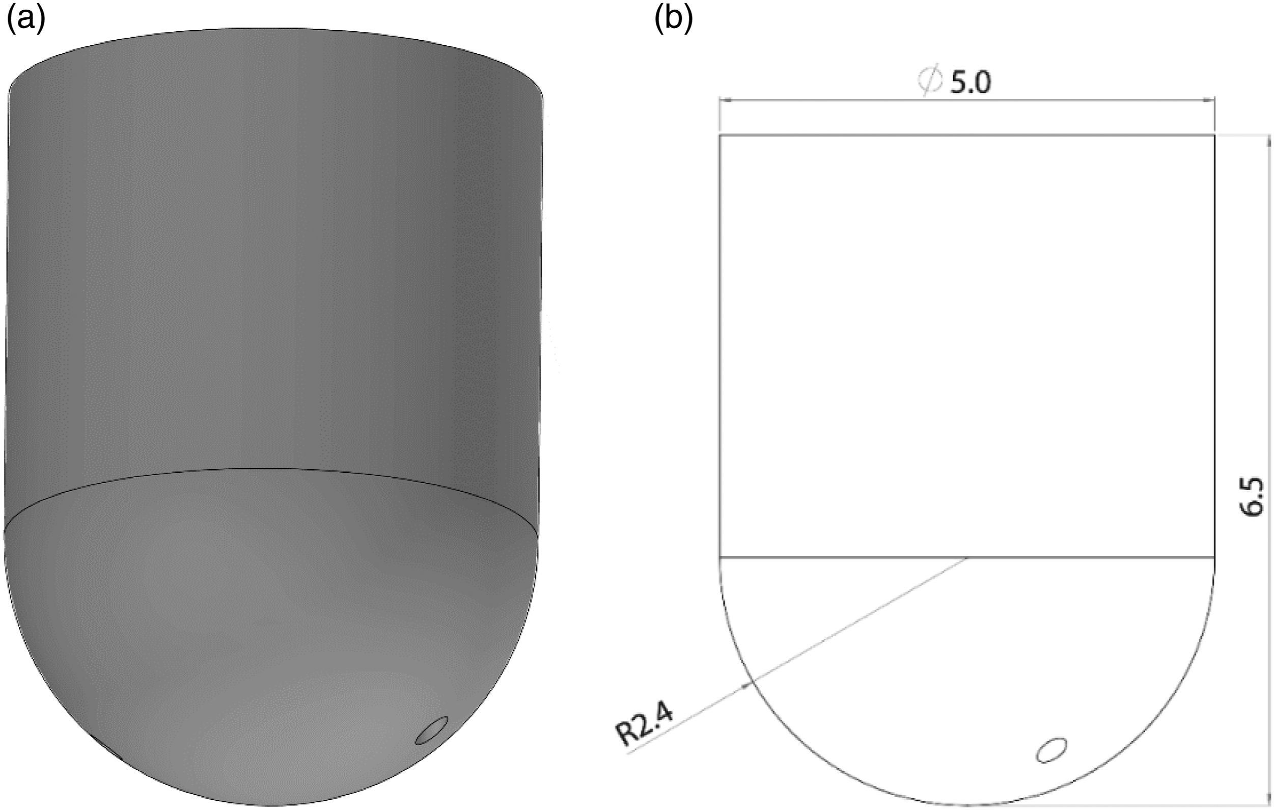
Lateral (lateral (greater trochanter) protuberance
The greater trochanter forms a small inferior shelf that serves as a load-bearing aspect in seating. To determine size, four different femurs were obtained and measured. The lateral breadth of the greater trochanters averaged 2.5 cm. The length of the greater trochanter was measured by the distance between its superior aspect to the lesser trochanter. The mean length of 5.7 cm was used to define the lateral protuberance length of 5 cm. Slight changes in dimensions were made to accommodate pressure sensors. Figure 3 illustrates the form and dimensions of the element that projects below the top plate. In summary, the lateral protuberance of the model was defined as 3 cm wide and 5 cm in length with a square 2 ½ cm flat inferior surface to accommodate a pressure sensor. Lateral Protuberance (a) form (b) dimensions in cm.
Posterior (sacrum/coccyx) protuberance
The substructure for the buttock models includes a posterior protuberance that models the lower sacrum and coccyx. To create the abstracted element, multiple anthropometric measurements were captured to model the entire sacrum and coccyx, including sacral curvature, sacral length, width of S1 body, sacral length, sacral width, width of C1, coccyx length, coccyx thickness, sacro-coccygeal angle and intercoccygeal angle.13–18 In addition, MRI data of seated persons was used to supplement the anthropometry. This dataset has been reported in multiple publications although these values were not within the scope of the papers.19,20
Sacrum-coccyx anthropometric measurements used to abstract the model element.

The CAD design of the posterior element reflects the curve of the coccyx in the sagittal plane, and uses the location of the S5-C1 joint within that curve as an index. Figure 4(a) shows the coccyx CAD model, highlighting the S5-C1 joint location. The S5-C1 joint’s location is used later in positioning the element on the substructure. The Coccyx protuberance (Figure 4(b)) is also tapered to reflect coccyx segment widths shown in Table 2. Posterior Protuberance (a) form (b) dimensions in cm.
Substructure spatial dimensions
The three abstracted elements are mounted to a top plate and extend downward into the elastomeric shell, with the medial and lateral elements being spaced bilaterally. The spatial locations of the three protuberances are anthropometrically based. Figure 5 shows CAD model of substructure, including the renderings of the elements designed to accept internal sensors in one side (see Supplemental information for details). Model substructure with skeleton analogs.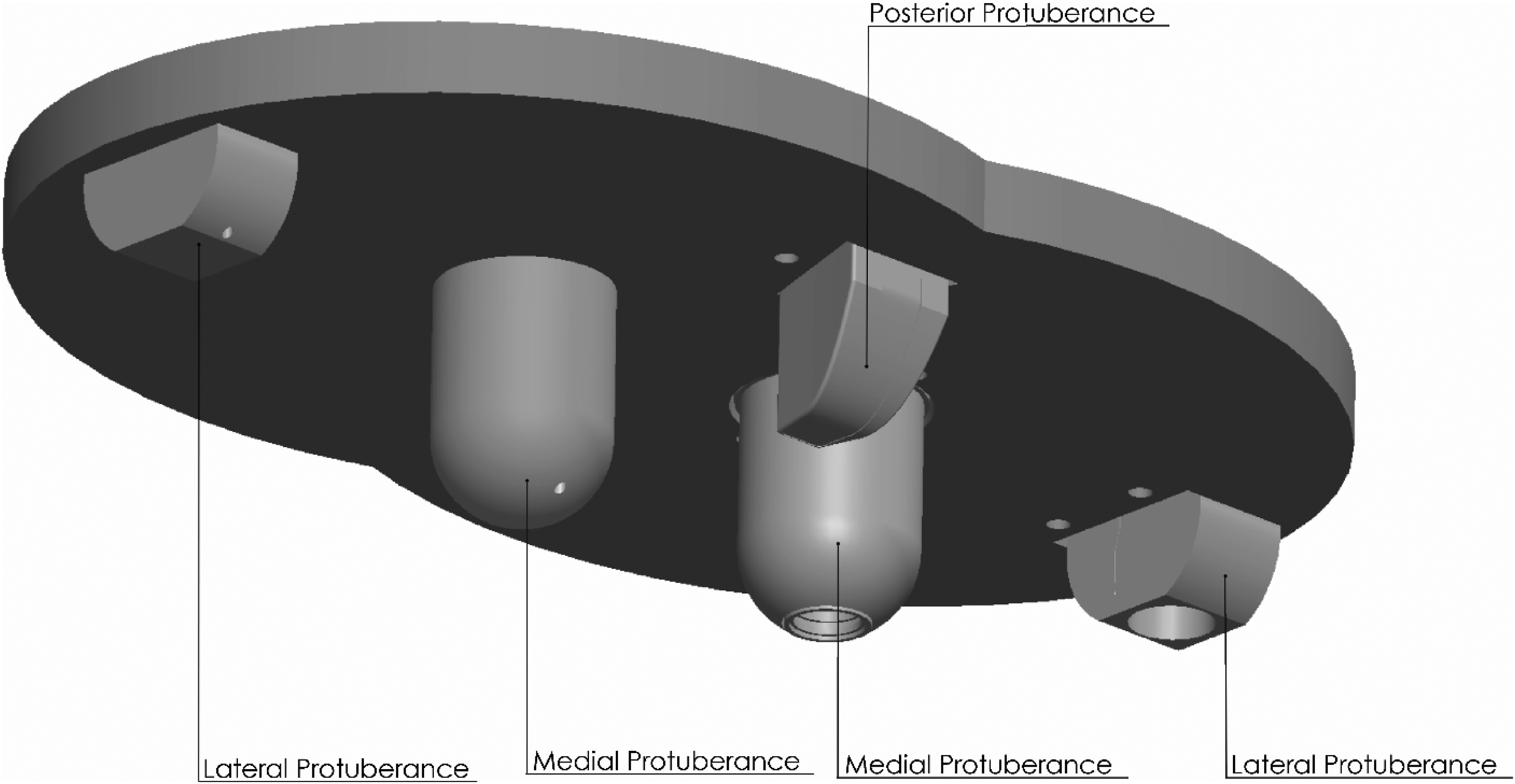
Medial Protuberance based upon ischial spacing
Multiple datasets that included ischial spacing were combined to define the distance between the inferior aspects of the ischial tuberosities.10,21–24 Combining the datasets involved calculations of both mean and standard deviation using established methods for combining parametric distributions. After aggregating in this manner, rounding was applied resulting in, an ischial spacing = 11 cm with a std dev = 1.2 cm. Scaling was then applied using the 50th, 84th and 97.7th percentiles, which represent mean, mean +1 stddev, and mean +2 stddev, respectively. As a reminder, this spacing was also used to define the separation of the inferior aspects of the buttock model shells so that the substructure protuberances were properly aligned within the respective shells.
Lateral protuberance based upon trochanter spacing
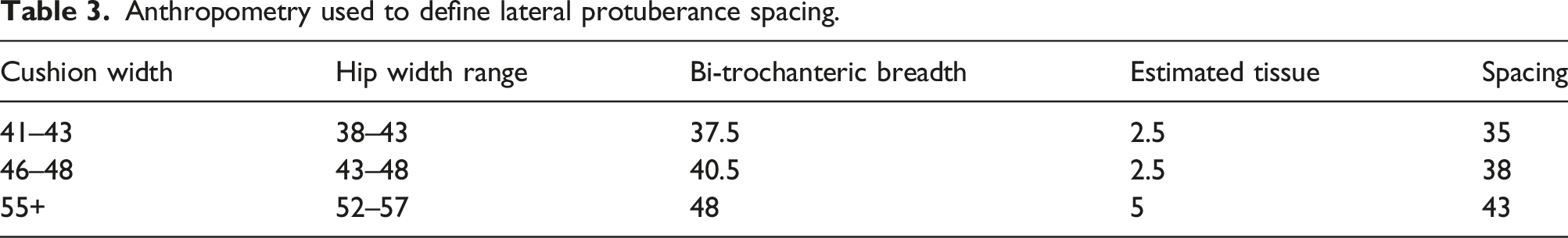
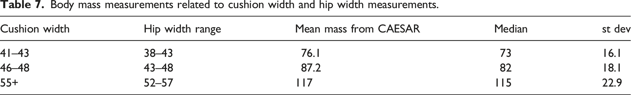
Bi-trochanteric breadth is an anthropometric measurement that seeks to estimate the breadth of the hips. Bi-trochanteric breadth for each size cushion was determined based upon the expected user groups. A decision was made to assign a 5 cm hip width range to define the sizes of persons who would use each cushion width. Specifically, users with hip widths of 38–43 cm were defined for the 41–43 wide cushion, 43–48 cm for the 46–48 cm size cushions and 52–57 cm for the 55+ wide cushions. The Civilian American and European Surface Anthropometry Resource (CAESAR) database was queried over each hip width range to obtain bi-trochanteric breadth anthropometry. 25
Anthropometry used to define lateral protuberance spacing.

Medial and Lateral protuberance spacing for 40 cm wide model (in cm).
Spacing parameters that define Medial and Lateral protuberance positions.

Height relationship between the ischia and trochanter
The ischial tuberosities are the most inferior aspect of the skeleton in a seated posture with the greater trochanters situated laterally and superior. The relative heights from a horizontal plane of these structures are important to consider when designing a model. This can vary slightly according to pelvic tilt and rotation of the femur, so attention was paid to both during measurement. Relative height differences between inferior aspects of the ischial tuberosity and greater trochanter were measured on four skeleton models and using MRI scans of 3 seated individuals. The height difference between these anatomical structures was approximately 4 cm from each data source.
Posterior protuberance (coccyx) positioning
To fully define the compliant model substructure, the posterior element, or abstracted coccyx, had to be positioned relative to the medial protuberance using A/P and vertical relative positions. The location of the sacrum and coccyx relative to the inferior aspect of the ischial tuberosity was documented to inform the design of the substructure elements. MRI scans of 16 seated individuals were measured using the tip of the ischial tuberosity and the S5-C1 joint, both of which are easily identified in the scans. This analysis resulted in S5-C1 being located, on average, 8 cm posterior and 4 1/2 cm superior to the inferior aspect of ischial tuberosity. These dimensions were applied to the 40 cm model. The scaling of the A/P location of the coccyx for larger models was based upon the MRI data. The standard error of measurement was ≈3 mm, which was rounded to ½ cm to define the locations of the larger models (i.e., 8 ½ and 9 cm, respectively).
Figure 7 shows the position of the S5-C1 index on the posterior element relative to the bottom of the medial protuberance for the 40 cm wide model, from a lateral view. Of note is the fact that the location of the distal end of the coccyx will be closer to the ischial tuberosity in both directions. The anterio-posterior distance is scaled to be larger for larger model sizes, as seen in Table 5. Horizontal and vertical distance from medial protuberance to the abstracted location of the S5-C1 joint. Coccyx positioning relative to medial prominence bottom, based on model size.

Shape of compliant shells
Compliant shells were designed to reflect a two profile shapes and to accommodate the rigid substructure. The two shapes were designed to represent different types of persons. The elliptical model exhibits a smooth tapered shape that reflects person with fairly typical buttocks tissue. In distinction, the trigonometric model is more peaked, so it represents persons who exhibit atrophy or poor tissue bulk. The models are axisymmetric so the overall shapes are designed for one side and then mirrored to the other side to create the full form.
One requirement was to design both models to accept the same substructures. This necessitated synching not only overall width and breadth, but also the separation of the inferior aspects of each model, as seen in Figure 8. As a result, the inferior aspects of both models are reflective of the bi-ischial distance measurements used in substructure design for each size. Frontal view of models illustrating equal model widths and distance between inferior aspects.
Elliptical model
Major and minor axes of ellipsoid and ischial spacing used for creating the 3 elliptical model sizes.


(a) Elliptical Model with 2 curves defining its shape (b) Curve A seen in front view (c) Curve B seen in side view.
Three model sizes in front and side view – elliptical shape.
Trigonometric model
The trigonometric model is more complex. Both the medial-lateral direction (Curve A) and the antero-posterior direction (Curve B) are defined by a primary trigonometric segment and a small elliptical segment at the edges, as seen in Figure 11. (a) Trigonometric Model with 2 curves defining its shape (b) Curve A seen in front view (c) Curve B seen in side view.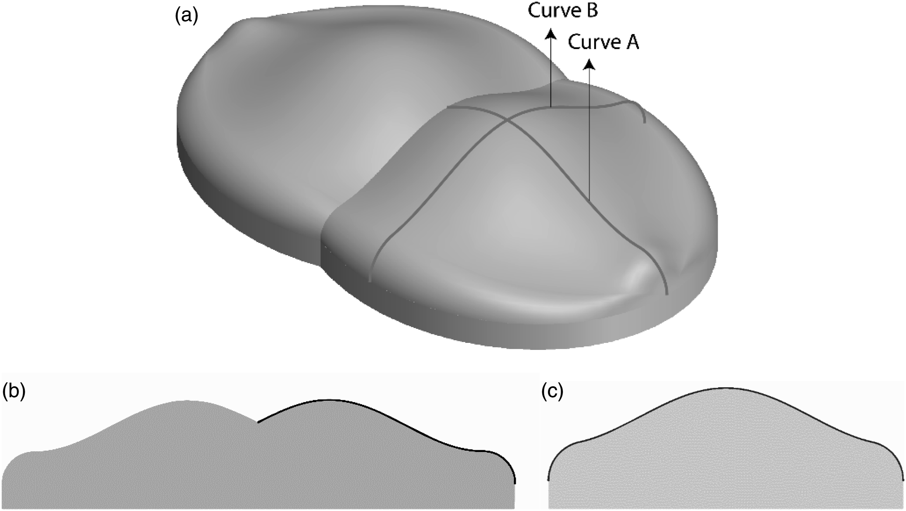
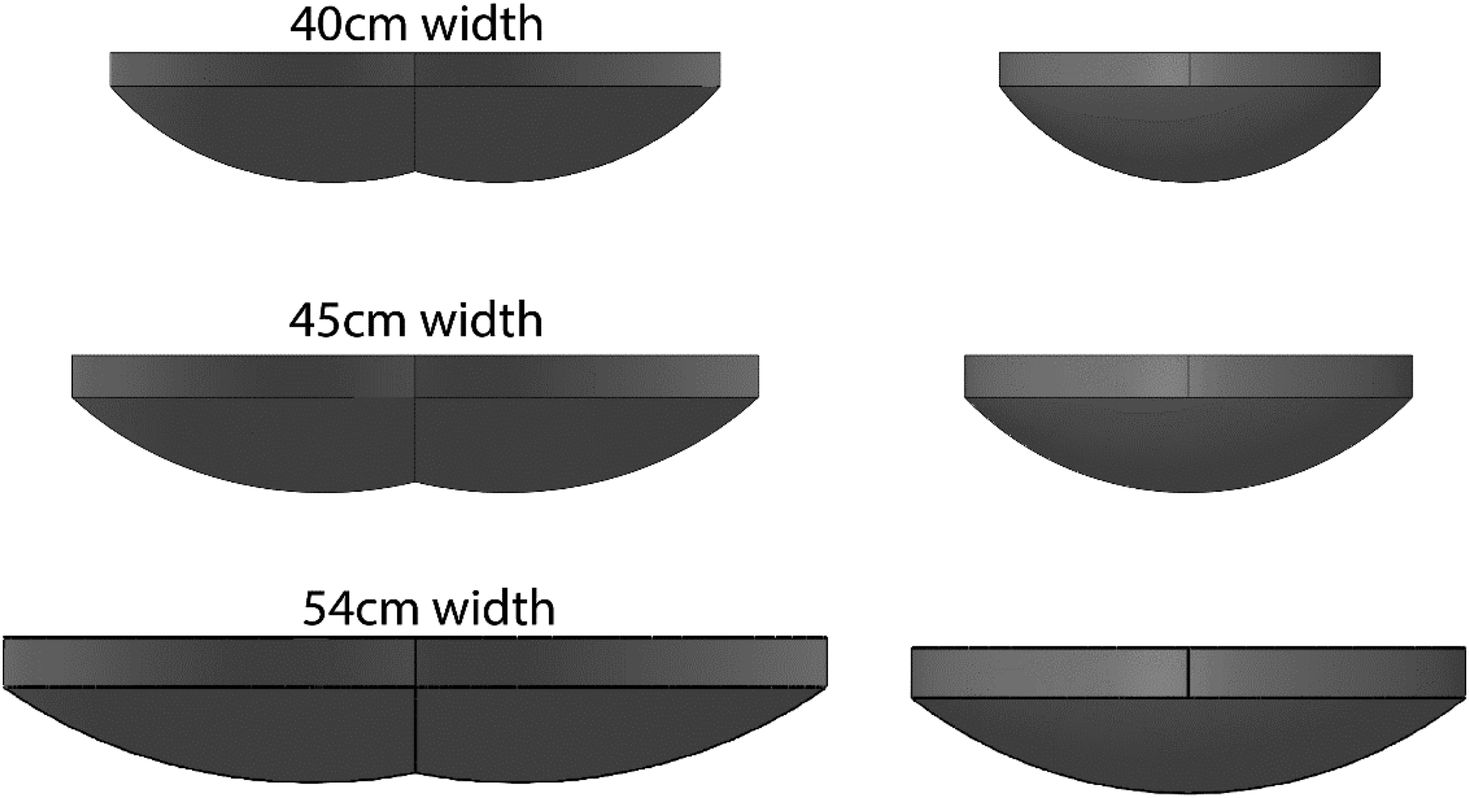
As with the elliptical model, one half of the shape is defined and mirrored to create the complete profile. Figure 12 shows all 3 trigonometric models. Three model sizes in front and side view – Trigonometric shape.
Human mass and body segment parameters
Loading of the model was calculated based upon two sets of data, body mass and body segment parameters. Body segment parameters were applied to determine the percentage of body weight represented by the body that impart force on a cushion in seating. This was defined as the body mass with a disarticulation of the hips, to remove the mass of the thigh, shank and foot. Five references were used that reported body segment parameters and their data was combined.26–30 The results indicate that 65% of body weight is represented by the pelvis, and upper torso.
Body masses
Body mass measurements related to cushion width and hip width measurements.
Defined lower and upper load values for each model width.

Summary
The descriptions of anatomically-based parametric buttock models serve dual purposes. Primarily, these buttock models can be used within cushion testing to measure wheelchair cushion performance. Models are defined that reflect different presentations of soft tissue and overall body size and mass. This results in a family of model designs that can be used to evaluate cushion performance reflective of the many types of persons who use wheelchair cushions. Secondarily, the descriptions serve as illustration of how anthropometric data can be applied to the design of anatomical phantoms that reflect both soft tissue and skeletal anthropometry. The detail offered within the Supplemental material and publicly-available database can be used to design a variety of human phantoms.
The 40 cm elliptical and trigonometric models were fabricated based upon the described configurations and instrumented with pressure sensors. An accompanying test method, use to evaluate cushion performance, was developed and is described elsewhere. 31 A full description of model fabrication, including CAD files and instructional videos are housed in an open-source database and licensed under Creative Commons (CC BY 4.0) (http://hdl.handle.net/1853/67080)
Supplemental Material
Supplemental Material - The design of a family of parametric anatomically-based compliant buttock models to evaluate wheelchair cushion performance
Supplemental Material for The design of a family of parametric anatomically-based compliant buttock models to evaluate wheelchair cushion performance by Stephen Sprigle, Yogesh Deshpande and Chris Bartlett in Journal of Rehabilitation and Assistive Technologies Engineering.
Footnotes
Acknowledgements
The authors thank Emil Muly for assistance in model fabrication.
Declaration of conflicting interests
The author(s) declared no potential conflicts of interest with respect to the research, authorship, and/or publication of this article.
Funding
The author(s) disclosed receipt of the following financial support for the research, authorship, and/or publication of this article: This project was supported by the National Institute on Disability, Independent Living, and Rehabilitation Research (NIDILRR grant number 90REGE0001-01-00) through a subcontract with the University of Pittsburgh. The contents do not necessarily reflect the endorsement by the Federal Government or the University of Pittsburgh.
Guarantor
SS.
Contributorship
SS conceived the project, collected background information, and developed design criteria. CB performed CAD design and model fabrication. YD performed CAD design and collected data. YD and SS analyzed data. SS and YD drafted the manuscript. All authors were provided the final manuscript for review.
Supplemental Material
Supplemental material for this article is available online.
References
Supplementary Material
Please find the following supplemental material available below.
For Open Access articles published under a Creative Commons License, all supplemental material carries the same license as the article it is associated with.
For non-Open Access articles published, all supplemental material carries a non-exclusive license, and permission requests for re-use of supplemental material or any part of supplemental material shall be sent directly to the copyright owner as specified in the copyright notice associated with the article.