
Abstract
This paper presents the design and performance analysis and experimental study of a 3-
Keywords
Introduction
An exoskeleton is a wearable robot designed to supplement one or more abilities of the human body part to which it is connected. Exoskeleton usage is often motivated by energy conservation for functional bodily limbs or strength assistance for limbs that have weakened or total loss of functionality. These capabilities stand to improve the quality of life for people suffering from mobility disablements, which have been reported to affect approximately 20,639,200 non-institutionalized individuals in the United States (7.1% of the total US population) in 2013 1 and 2,512,800 Canadians (7.2% of the total Canadian population) in 2012. 2
The presence of one or more joints with multiple active degrees-of-freedom (DOFs) in the pertinent limb complicates the design of an exoskeleton with complete kinematic compliance. One method to address this challenge is to restrict the motions that the exoskeleton supports about the multi-DOF joint, instead of providing total kinematic compliance. This is the common design method for current exoskeleton research and technologies.3–6 Consequently, most present-day exoskeletons are composed of kinematic open chains: serially connected single-DOF rotary or prismatic joints between rigid linkages. However, Kizir and Bingul conclude that closed-chain parallel manipulators (PMs) have better performance than their serial manipulator counterparts with regard to positioning accuracy, speed, force application, and payload-to-weight ratio.
7
Thus, in order to improve the robotic performance and kinematic functionality of exoskeletons, we propose the use of parallel robots paired with a mechanical structure that transmits motions to the targeted body part in a comfortable, non-restrictive way. One parallel robotic structure that has potential for use in such an application is the 3-
This paper investigates the performance of the 3-
Kinematic considerations for the 3-R RR manipulator
Kinematic architecture
Figure 1 shows a geometrical schematic of a generalized 3- Schematic illustration of a generalized 3-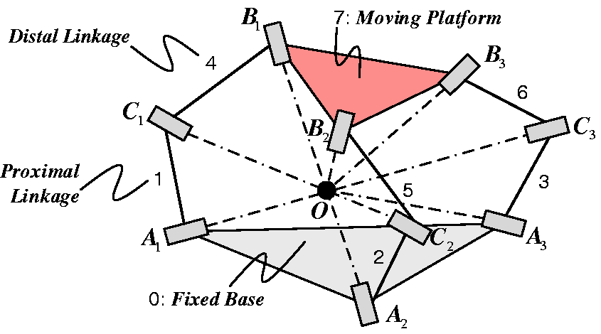
Note that two notable embodiments of the 3- (a) Agile Eye and (b) Agile Wrist embodiments of the 3-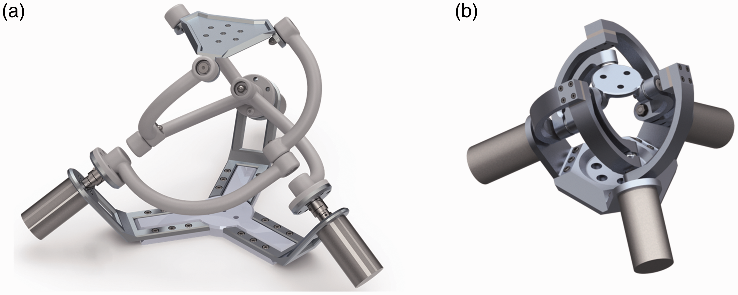
Inverse kinematics derivation
Inverse kinematics analysis for the 3-
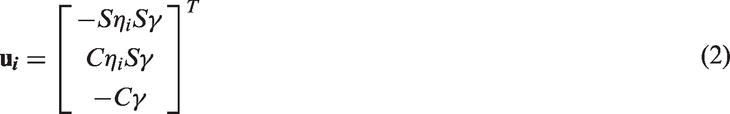
To start, direction vectors 3-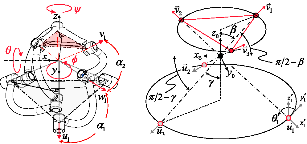
Scalar constant α1 specifies the angle between each actuated Ai joint and the corresponding proximal Ci joint within the plane containing both of these joints as well as the global origin, O. The value of α1 used for the 3-
Finally, scalar constants η1, η2, and η3 are used to specify the locations of the active joints associated with direction vectors
Equations for the
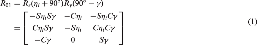
It follows that the x-axis of the resulting R01 orientation frame is equal to the direction vector
Direction vectors

Now, to obtain expression in terms of the global coordinate system, the set of rotations described above must be pre-multiplied by R01. Finally, the set of direction vectors

Similarly to the derivation for

Again,


Given that all direction vectors

Now, through substitution of equations (4) and (7) into equation (8), a set of relationships between the system inputs and outputs is obtained. Upon performing this substitution and simplifying the result, the following equation is produced.


It follows that the input angle required to achieve a desired end-effector positional output can be found with the following equation.

Equations (10)–(13) represent the solution to the inverse kinematics problem for the 3-
Jacobian analysis
A number of generally accepted performance indices for parallel manipulators are often published as a method for comparing various robotic manipulators.
16
The values of these indices usually have physical significance and applications for design optimization.
17
The three indices considered in this paper, which are manipulability, dexterity, and rotational sensitivity, all derive from the Jacobian matrix of a manipulator. Thus, the 3-
To start, a vector


As shown above, two components of the Jacobian are produced: J
x
and J
q
. The combination of these components yields the complete Jacobian matrix.

It is important to note that the Jacobian associated with a parallel manipulator, as in equation (16), is derived as the inverse of a serial manipulator’s Jacobian. 15
when equation (15) is written once for each of i = 1, 2, and 3, three scalar equations are produced. These can be arranged in matrix form as follows.
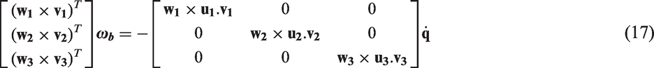
Combining equations (16) and (17) yields a complete form of the 3-

Recall that vectors
Hip exoskeleton design based on performance indices
With the 3- Considered 3-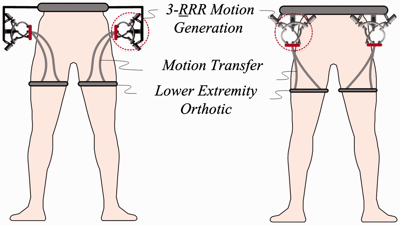
Manipulability
Forces experienced by joints within parallel manipulators tend to become large when such a device nears singular configurations.
16
Thus, the ability to quantify a manipulator’s nearness to singular configurations is useful. Manipulability is a common performance index used to accomplish this quantification. It is defined as the absolute value of the Jacobian’s determinant,
18
as given in equation (19). Alternatively, this index can be interpreted as the Jacobian matrix’s minimum-magnitude eigenvalue.

In mechanical terms, manipulability represents a manipulator’s ability to successfully create a desired velocity at its end-effector.
19
Alternatively, this index can be understood as the ellipsoid volume resulting when a unit sphere is mapped from the manipulator’s n-dimensional joint space into Cartesian space through its Jacobian matrix and a constant proportionality factor;
20
recall that n represents the active joint count for the manipulator. It follows that a manipulator achieves greater manipulability performance if its ellipsoid has a greater uniformity, or isotropy, characteristic.
21
Such an isotropy index for manipulability can be quantified as follows.
3-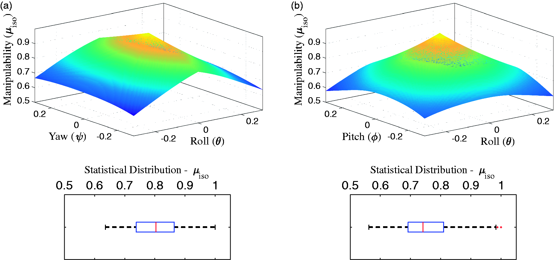

According to the surface plots, the manipulability of the 3-
Dexterity (condition number)
Because a manipulator’s control scheme generally relies on its joint position coordinates, any errors between the expected and actual joint coordinates cause errors in the end-effector’s position and orientation.
16
This end-effector error can be determined through multiplication of the errors in the joint coordinates by a scaling factor: the condition number, k.
22
A manipulator’s condition number is obtained from the Jacobian matrix as follows.22–25

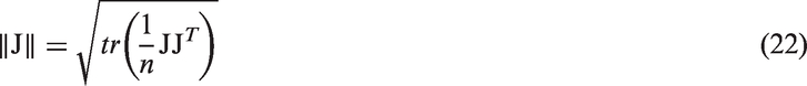
Gosselin proposes that the condition number’s inverse be used to quantify a manipulator’s kinematic accuracy;
24
this criterion is called the local dexterity index, denoted by ν.

Again, allowable values for ν are constrained between 0 and 1; zero indicates a singularity, and greater values correspond to increasingly accurate motion generation at the end-effector.
Figure 6 depicts dexterity index surface plots and statistical box plots for both body-attachment arrangements of the 3- 3-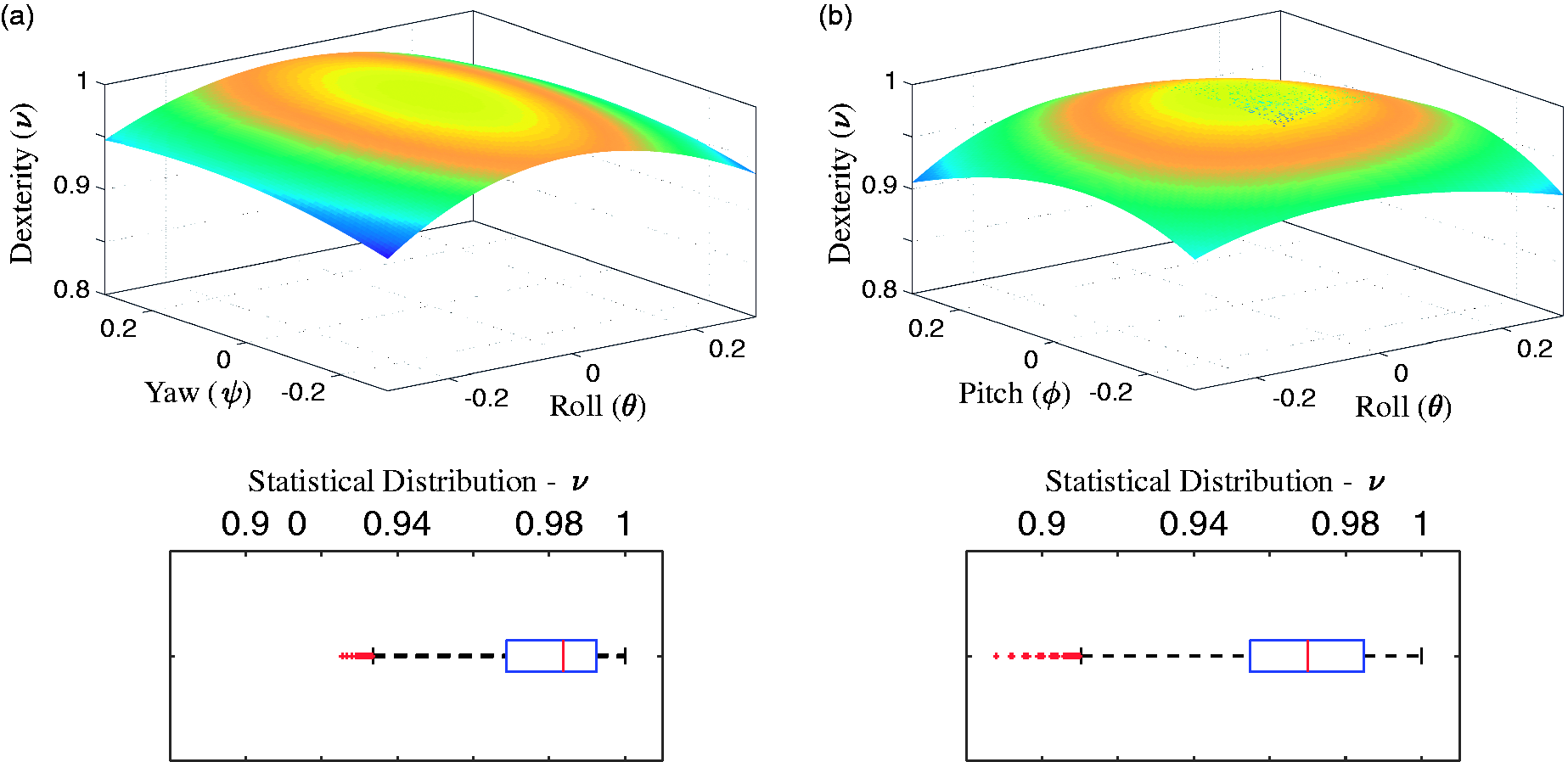
Rotational sensitivity
The rotational sensitivity index of a manipulator indicates how reactive its end-effector is to changes in active joint states. More specifically, it is the maximum-magnitude rotation of the end-effector under a unit-norm actuator displacement;
20
it is given by either the 2–norm or the ∞–norm of the Jacobian matrix as follows.

Figure 7 shows the sensitivity results for the 3- 3-
Experimental study on the 3-R RR manipulator
Mechanism fabrication details
In preparation for experimental tests on the 3- (a) Experimental prototype of the 3-
Experimental results
The purpose of our experimental study on the 3-
The experimental results of Figure 9 depict the reference and response signals associated with the individual system motors. These are the motions required by the selected design and body-attachment scheme to achieve the hip motions associated with normal gait cycles at the end-effector, as determined by the inverse kinematics algorithm. In turn, Figure 10 presents an overlay of the resulting end-effector orientation angles, as captured by the system IMU, and the desired angles, as provided by the OpenSim software.
Comparison of reference signal and encoder feedback from each actuator during gait motion tracking. Comparison of desired end-effector orientation and IMU-measured value during gait motion tracking.

The results shown in Figures 9 and 10 indicate that the 3-
As shown in the absolute error plots of Figure 11, the error in ψ rises periodically during a rapid extension motion of the hip joint. This systematic error can be primarily attributed to the experiment’s non-optimal control method, which does not account for inherent nonlinearities of the device’s dynamics and inhibits the device from adequately tracking its reference signal. Therefore, the development of a more effective control algorithm would likely reduce the end-effector’s orientation errors. Given this solution and the otherwise small magnitudes of error, it is feasible that the 3- Absolute error between desired end-effector orientation and IMU-measured value during gait motion tracking.
Conclusion and future work
This paper proposes the use of the well-established 3-
The performance study results indicate that the body-interfacing arrangement that orients the manipulator’s x-y plane parallel to the body’s sagittal plane is superior in terms of average value and variability for manipulability, dexterity, and rotational sensitivity indices. As can be expected, the manipulator’s performance is optimal when configured at its initial ‘home’ orientation and degrades as the end-effector moves away from this state.
For the experimental study, a prototype manipulator’s end-effector was controlled to track the motions experienced by a human hip joint during normal gait cycles. In summary, the general agreement between input and output signals depicted in the resulting figures suggests that application of this 3-
Footnotes
Declaration of Conflicting Interests
The author(s) declared no potential conflicts of interest with respect to the research, authorship, and/or publication of this article.
Funding
The author(s) disclosed receipt of the following financial support for the research, authorship, and/or publication of this article: This work was supported by the Natural Sciences and Engineering Research Council of Canada (NSERC).