
Abstract
The design and manufacturing of affordable medical assistive devices represents a major challenge for developing countries where resources are much more limited than in rich countries. The engineering design process focuses on developing better devices and systems with a low impact on the environment and the most functional and efficient performance, at the lowest possible price. In this context, the mechatronic design is perhaps the most complete way of thinking about performing concurrent design tasks which provide fully of mechanical, electronic, informatics and intelligent control systems integration. This design process can take advantage of many computer-aided tools, which play a key role in the modern methods of optimization and reduce the cost of prototyping. This work presents the mechatronic design process of an affordable assistive robotic bed, from the main requirements through the mechanical design and up to the integration of the electronics and the embedded control, while industrial design suitably merges to all the modules of the robotic bed. The work was developed in cooperation with a set of experts at the Hospital Juarez de Mexico who provided their very specific necessities for the designers and more important for the patients.
Introduction
Mechatronics dates back to 1969, when the Yaskawa company in Japan coined the term to describe the way mechanics and electronics are merged to develop intelligent devices and systems. Steady advancements in technology have vastly expanded its use. Currently, a major focus area for mechatronics is the design of assistive devices. On the one hand, by integrating mechanical and electrical hardware with information technology and embedded control, designers can deliver highly sophisticated functionality. Therefore, mechatronics tends to improve the design and operation of assistive devices, enabling its use in a growing range of medical applications. On the other hand, this functionality has paid the price of higher costs of production which has a severe impact on the affordability of such devices, especially for developing countries which are importers of foreign technology.
The growing demand for medical devices and the lack of experienced human medical resources represents a major impediment to effective treatment of patients, particularly in developed countries with aging populations. In the specific case of Mexico, recent studies by the National Population Council reveal that the life expectancy will increase from 73.6 years in 1995 (71.3 for men and 75.9 for women) to 80.4 (78.4 for men and 82.3 for women) in 2020 and, finally, 83.7 years (82.0 for men and 85.5 for women) in 2050. 1 In addition to this, the continued demand for rehabilitation therapies, mainly for motor rehabilitation due to accidents affecting the limbs of humans or for the elderly population, emphasizes the lack of adequate medical staff. Therefore, in the next years assistive devices will support medical staff by reducing the intense load of physical interaction with patients.
Assistive devices are always priority to demanding fields to satisfy hospitals needs and more importantly to improve patient comfort and the quality of the devices that assist his rehabilitation. Those devices must be designed to fulfill successful healthcare services. 2 In this context, we have recently proposed a diagnosis methodology that aims for technology project development and represents a framework that might be used to assess the feasibility of the development of a device or system by analyzing its impact in a specific environment. 3 Once it is decided that it is a feasible project, it can be suitably developed. By applying our methodology to the Hospital Juarez de Mexico (HJM) it was found that the device that has most impact on the medical institution is the hospital bed. 3 As explained in “Mechatronic design approach,” this diagnosis established the main criteria for the mechatronic design of the robotic bed.
Different models of robotic bed manufacturers.

In this work, the design approach for the hospital bed goes beyond, and it is based on patients', nurses' and stretcher-bearers' specific requirements. Hospital human resources are the people in daily contact with real situations and needs. For this reason, their feedback is essential to producing a useful hospital bed. This design also forms the basis for considering a functional set of positions demanded by real bed needs. Then for each required position a mechanism synthesis stage creates a solution for the motion of each required tool. Finally, using the tools of mechanical engineering, the complete design can be developed. It is important to mention that the bed construction involves design and manufacture in various areas (mechanical, electronic, industrial and graphic design). This integration produces a functional device in combination with an intelligent system. 11
Special features and functions
Traditionally, special functions are offered by manufacturers as specific and expensive extensions of standard models of hospital beds. Nevertheless, our approach is to satisfy the requirements of the market, that is, the users of the bed. From visits to HJM, our study obtained results on the analysis of the dynamics of running a hospital room for the different usage scenarios and the description of the users involved in the use and maintenance of a hospital bed. From these results, we defined a list of general requirements which must be fulfilled in order to achieve an appropriate working relationship and successful use of this specialized medical device. In addition, to satisfy this feature set, additional considerations complying with IEC-60601-52 and UNE-EN 1970 standards were taken into account. The final set is listed below.
Ensure the stability of the device in any of its positions. For security, no user should have contact with mechanical parts. The railings must have free movement in any position. Access controls should be comfortable and live (even without electric energy). Access medical peripherals and accessories must be free and comfortable in any position. The position of the device should not limit the use of peripherals. It must attend the medical user to find the right position for the patient in different circumstances given by the condition of the patient. The rails and foot-board should allow visibility of the medical staff at any time and should not obstruct patient monitoring. It should allow access to perform common toilet tasks. Ensure stability in patient transfer conditions, even with two people on it. The device should provide a good service (maintenance) to the user during their stay in hospital. It must make the patient's stay comfortable taking into account as far as possible the emotional aspect of it (e.g. sense of stability and safety during movements). It should avoid, prevent and/or minimize any risk, both use and health, for all users, especially for the patient A safety loading of 3000 N, must be resisted by the mechanical structure. A minimum and maximum height of 47 cm and 90 cm respectively must be provided by the bed. It will be useful for the “help to stand up” position.
Positions
Several hospital bed manufacturers provide a wide range of models that are suitable either for intensive therapy or for hospitalization. Depending on specific requirements, some positions are provided by each bed model. The most common positions are orthopedic, cardiac, Fowler and Trendelenburg. Nevertheless, other useful positions are foot elevation, panning or tilting, and sit.
12
From the universe of possible positions, the results of our study indicate that there are 12 required positions, depicted in Figure 1. It is important to note that the home position includes vertical motion, which provides the adjustable height of the hospital bed.
Twelve required positions for the hospital bed.
In order to achieve the desired positions, different mechanisms were synthesized to provide the desired ranges of motion. 13 Such ranges were also obtained by an ergonomic study which was carried out at the Center of Investigation in Industrial Design in Mexico City. 14
Mechatronic design approach
One mechatronic design key is to develop tasks of mechanical, electronic, control and industrial design in a concurrent fashion at the same time that full and harmonic integration of all the components is achieved. This is in fact an actual problem from the mechatronic design point of view. 15 A lot of information from several areas must be processed in order to fulfill all criteria for the design. Then, during the development of the design tasks a high degree of coordination must be achieved. The following section describes the positions and special feature requirements obtained by a serious study at HJM over two months of applying our diagnostic methodology. 3 About 300 medical experts were asked to define these requirements. As a benchmark for the requirements, Latin-American patients' heights were considered an essential part of the design process. 16 In the following sections, the tasks for the mechanical design, electrical design, control system design, intelligent system and industrial design are described. It is fundamental to remark that all the tasks were carried out in a concurrent fashion as established by the mechatronic approach.
Mechanical design
The mechanical design is mainly concerned with the mechanism synthesis. It is important to indicate that to render appropriate motion to each mechanism linear actuators of a specific trademark were selected due to certification with the international standard IEC-60601-52, which is the standard dedicated to electrical beds. Mechanism synthesis is performed by using the required ranges of motion for each position obtained by the ergonomic study, 14 then by using standard optimization methods and working on mechanism analysis. 17 To simplify this task, a group of modular mechanisms were synthesized and they are described below.
Base mechanism
The base of the bed must provide enough stability to prevent falls of the patient or any other from the bed at rest and during handling. Our device must not cause any situation dangerous to the patient's health. In order to reach our objectives, a rectangular base is proposed as shown in Figure 2, coupled with the elevation mechanism. To render the bed mobile a set of four Tente© castor wheels were firmly attached to the base. Moreover, they have the function of directional brake or total brake to ensure the safety of the patient when the bed is at rest.
Elevation mechanism for the hospital bed.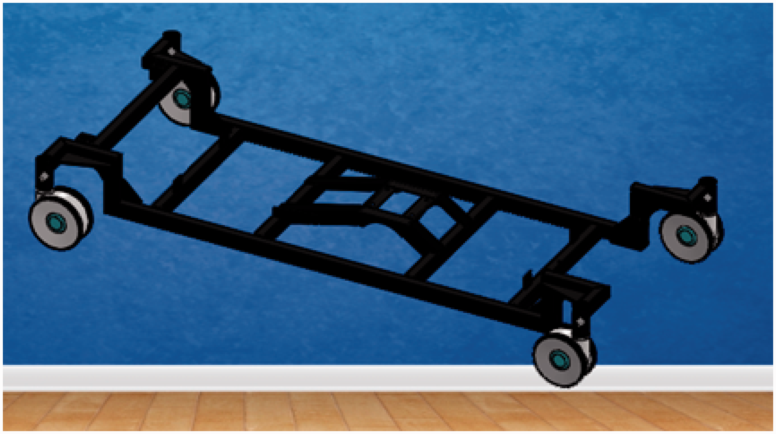
Elevation mechanism
This mechanism consists of two slider–crank mechanisms coupled to a six-bar mechanism which allows vertical and longitudinal displacement of the section mechanism. The elevation mechanism is also responsible for the Trendelenburg and anti-Trendelenburg positions and it is mounted on the base of the robotic bed, as in Figure 2.
Figure 3 shows the mathematical model used to synthesize the elevation mechanism. Using the standard notation for mechanism analysis, the six-bar mechanism responds to the following set of equations
Mathematical model of the elevation mechanism.

Tilt mechanism
This mechanism is directly coupled to the elevation mechanism by six SAE grade 1 screws and nuts. Its motion is controller by a slider–crank mechanism with a special linear actuator, coupled to a hinge-like mechanism; see Figure 4. This mechanism causes the sections mechanism to rotate in the sagittal plane of the bed, and thus it is responsible for the right and left tilt positions in Figure 1.
Tilt mechanism for the hospital bed.
Sections mechanism
Figure 5 depicts the sections mechanism. It is a set of hinge-like open chain mechanisms where the whole body of the patient must rest. The first link of this open-chain mechanism corresponds to the backrest, which is coupled to the slide-guard mechanism, described in the next section. In the second link of the section mechanism the patient's hip rests. This link is welded to the tilt mechanism. The third and fourth links correspond to the leg and foot mechanisms, respectively. The whole mechanism is isolated in Figure 5.
Sections mechanism for the hospital bed.
Leg mechanism
This section is designed as an inverted rod–crank mechanism; see Figure 6. The equations modeling this mechanism are
Leg mechanism for the hospital bed.

In this case, vector r1 is fixed while vector r4 represents a linear actuator which renders rotational motion to vector r2 through angle q2.
Foot mechanism
This section is also designed as an inverted rod–crank mechanism; see Figure 7. The equations modeling this mechanism are
Foot mechanism for the hospital bed.

In this case, vector r1 is fixed while vector r4 represents a linear actuator which renders rotational motion to vector r2 through angle q2. Note that vectors r1 and r2 are fixed. Moreover, vector r1 is fixed at the leg section.
Slide-guard mechanism
This mechanism is a slider–crank coupled to the backrest link of the sections mechanism; see Figure 8. The kinematic model for this mechanism is described by equation (4). Then, the synthesis stage follows the procedure for the elevation mechanism
Slide-guard mechanism for the hospital bed. Some positions in the ergonomic study for the robotic bed prototype.


Railing mechanism
Railings are designed as a four-bar mechanism. The main objective of this mechanism is to keep each railing in a vertical position in order to guarantee the patient's safety, as depicted in Figure 10.
Railing mechanism for the hospital bed (linear dimensions in centimeters).
Brake mechanism
To guarantee the whole robotic bed will stay at rest a brake mechanism is required. This mechanism is provided by the set of four Tente© wheels. Our design only considered a bar to activate the brake on each pair of wheels as shown in Figure 11. The bar is coupled to a slider-like mechanism.
Brake mechanism for the hospital bed.
Header mechanism
The header is required because a mounting for an electronic interface is required. It consists of an adjustable linear guide as shown in Figure 12.
Header mechanism for the hospital bed.
Electronic design
This section is concerned with the development of the electronic design. Electronics aims to feed the sensor assembly carrying the bed (tilt sensor, sensors lifting, weight sensors) and it is also responsible for providing power to all output devices (LEDs, touchscreen, motors) logically programmed via a central control device. Once the control part makes a logical or intelligent decision, the power stage is responsible for providing power to all output devices such as motors and lights. The electronics design was split into four stages: (1) selection of major electronic devices; (2) design and simulation of the electronic circuit schematic, (3) design of printed circuit boards (PCBs), and (4) design of a dedicated control system. To perform some of these tasks Altium Designer ©, a computer package for electronic design as well as free software and programming in C language, HTML5 and PHP programming on the Linux platform was used. Figure 13 depicts the electronic and control signals flow for the robotic bed.
Electronic and control design for the robotic bed.
The methodology for the electronic design was as follows. First, the selection of the electronic components to perform the different tasks of the robotic bed was carried out. These components are sensors, components for signal conditioning and power supplies. Then, the schematic design and simulation of electronic circuits was performed. Along with this document the set of .sch extension files representing each design schematic for manufacture was generated. This set of designs is made to a professional electronic standard that ensures proper operation during execution. Afterwards, the design PCB was developed. It is noteworthy that a total of six completely unique designs made especially for this application are presented. Next, a dedicated control system was designed. The way the robotic bed controls all peripherals through a detailed mainframe and how it performs each of the functions that involve electronics was described. Then, the programming of the LCD touch interface was performed, and finally the locations of all electronic components within the robotic bed were detailed.
Control system design
The main goal of the control system is to render smooth motion between the bed positions. This smooth motion is already rendered by the actuators, which are only commanded to a desired position using polynomial interpolation between each position.
The main task of the control system is to review, at each sampling period, the existence of errors in different parameters related to the bed's posture, giving priority to the bed height, horizontal and vertical tilt: if there is error in any of the aforementioned parameters a signal is sent to the actuator to increase or decrease the parameter. When errors are within an allowable range control, the control system proceeds to review the parameters backrest angle, thigh angle and foot angle.
Through the graphical interface (touchscreen in Figure 14), the user (nurse or doctor) can schedule routine bed movements, specifying the date and time they want the bed to change position automatically to one of 12 presets. The way control meets the above task is divided into two blocks or functions. The first is to compare the current date and time with the programmed one, and when they are equal proceeds to call the second function involved (routine). When the control system determines that it is time to change position, it calls a routine that writes new parameters into the tables.
Touchscreen control design interface.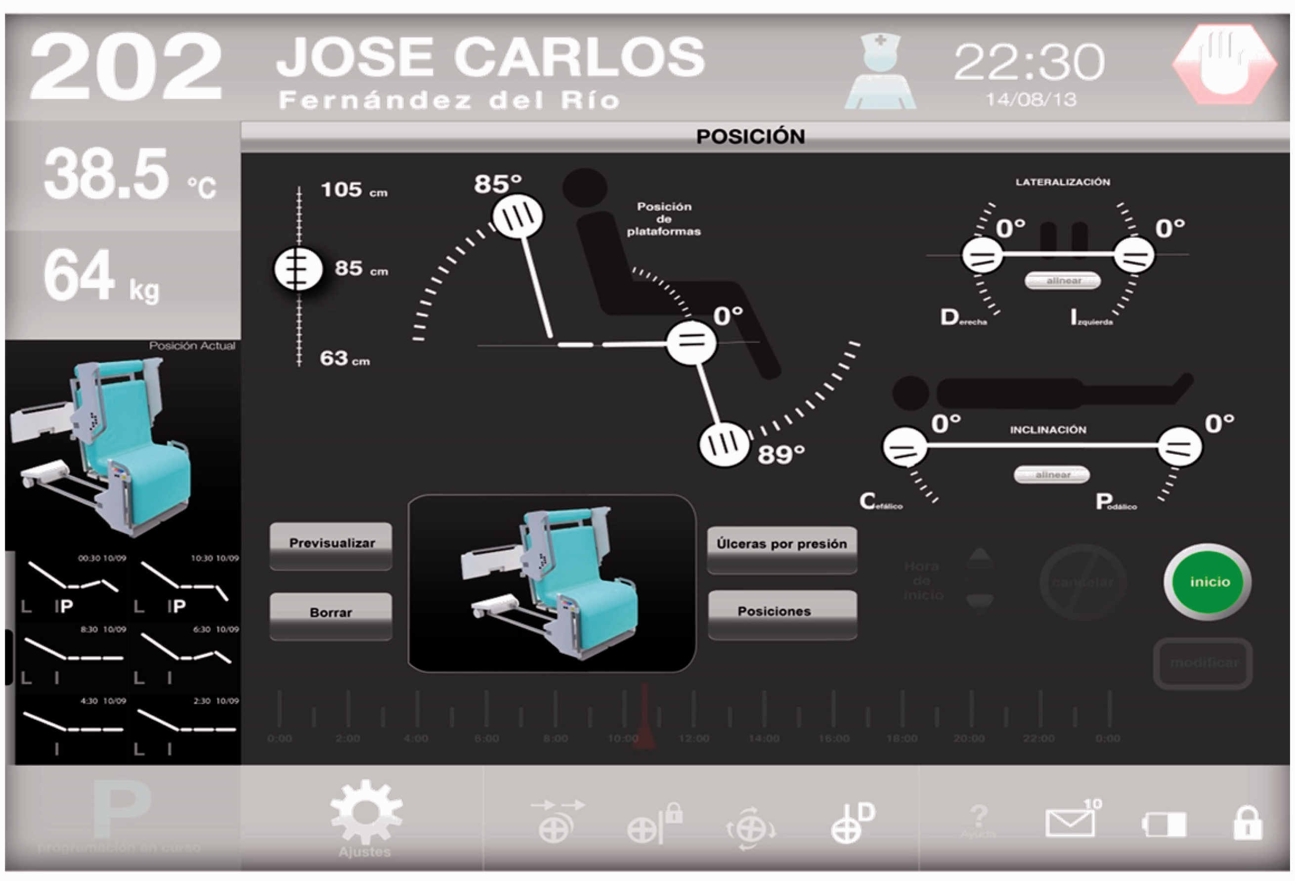
Intelligent system design
For the automatic motion of a robotic hospital bed, based on posture classification and identification, an intelligent monitor system was designed. This has been developed as a response to the patients who require a certain routine of motion application. The proposed intelligent system allows medical experts to program movements of the robotic bed by considering the patient's posture and time. The intelligent monitor system for body posture classification works in real time and is based on a histogram of oriented gradients (HOG) descriptor and a support vector machine (SVM) classifier. 18 Moreover, the intelligent system considers the problem of human posture classification with limited information, that is, sensors. Then, by applying digital signal processing, the original data is expanded to get more significant information for the classification.
Our robotic hospital bed is able to render several positions depending on the needs of a particular patient. The main task of the intelligent system is to decide when it is feasible and safe to move from a given position to a desired one. For this, a state transition diagram has been specially designed, guaranteeing safe transitions between the bed positions; see Figure 15.
State transition diagram.
Figure 16 shows the main stages of the Intelligent System (IS) for posture recognition. In the initial stage the images representing pressure distributions are obtained from the pressure sensor array. Then, in the second and third stages a feature extraction using HOG19 and SHIFT20 descriptors are applied over the pressure distribution images. For this, they are considered as gray scale images. After, in the fourth stage a database of features is constructed, and finally in the last two stages a model for feature classification and prediction is build by comparing the results of three classifiers: SVMs, decision trees and naive Bayes networks. To simplify the posture recognition we consider three basic postures: the right lateral decubitus, supine and the left lateral decubitus positions (see Figure 17), and since the prone position is almost the same as the supine position, its detection is achieved by an analysis of the pressure distribution. Figure 17 shows the three basic correct positions displayed as gray-scale images, obtained from simulated data of the pressure sensor array.
Main blocks of methodology for posture recognition. Three basic correct positions obtained from simulated data.

Industrial design
The industrial design was considered during the whole design of the robotic bed as an integral part of it, resolving from a formal geometric proposal the perceived image of the final object. Moreover, such design must communicate a modern medical image, that the user trusts during use, taking as general considerations communication, safety, comfort, and the necessary anthropometric measures for the proper use of a Mexican population based on percentiles tables. 16
Safety, from the industrial design point of view, is the set of conditions that guarantee that a patient will be protected from suffering new health problems, independent of those which led him to seek medical assistance. Therefore, this device must be able to function without this representing any risk to any of the different users. The robotic bed should provide inpatient accommodation 24 hours a day. This plays an important role in the recovery of the patient, providing convenience and comfort. The comfort of the patient depends on the state of his bed, especially if he uses it for long periods. Providing for the above patients depends directly on the proper relationship between the size of the user, and the dimensions and proportions of the area of the bed, as well as the physical qualities of the mattress and the materials to be used in building the device.
Main Industrial design requirements.

As indicated before, Mexican anthropometry (see Figure 9) was considered for the design of the industrial components. It is important to mention that norms IEC 60601 2-52 (standards for medical beds) and UNE-EN 1970 (adjustable beds for disabled persons) were considered for the industrial design. The components to design were covers for the railings and header mechanisms, removable parts as coatings for mechanical moving sections in contact with the mattress, cover mechanisms for lateralization and tilt, covers for lifting mechanisms and covers for the bearing area and electronic devices; see Figure 17.
In compliance with the intelligent system design, a cover for the touch screen was designed; see Figure 19.
Industrial design of the robotic bed.
Manufacturing results
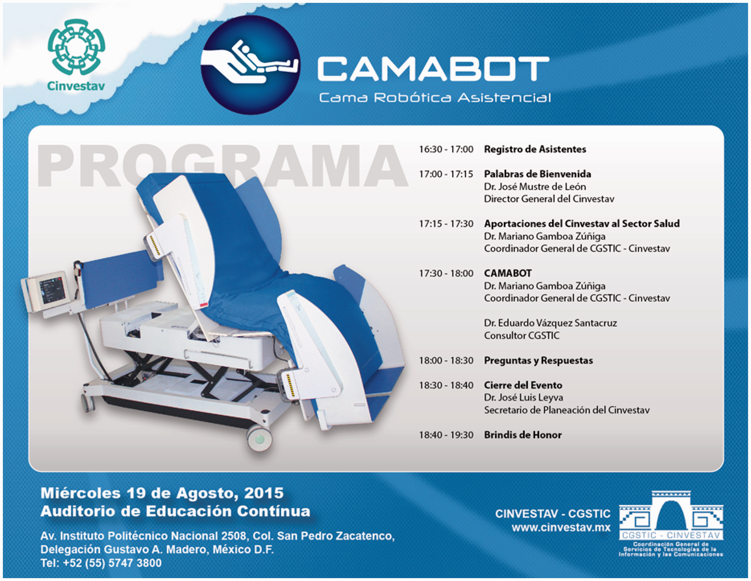
An image of the final presentation (http://phys.org/news/2015-09-specialists-robotic-bed-international.html) of the robotic bed is depicted in Figure 20. It is important to mention that the price estimation is based on the cost of materials for our robotic bed and it reaches US$13,000. This is only an approximated price, for a prototype not optimized for industrial manufacture. We estimate that, once a manufacturing optimization process is carried out, the final price can reach US$8000, which is clearly much lower than the commercial models presented in Table 1.
Touchscreen cover and top railing cover. Final presentation of the robotic bed.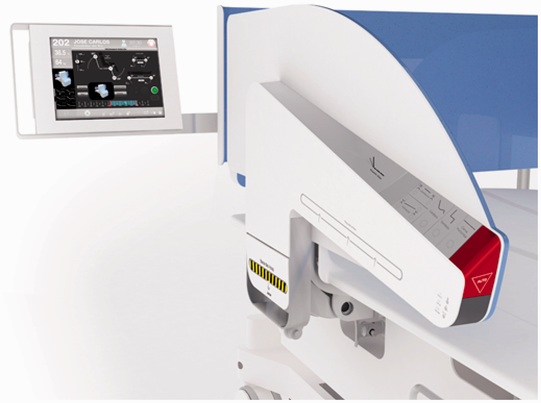
Manufacturing design of the various areas involved an effort that demanded high technical and technological capabilities. Subsequently, the integration also required high synergy to allow proper assembly giving rise to a functional device according to the requirements initially established. This requires a high degree of coordination and technical precision with a very small range of error. Corresponding parts of the different areas were manufactured separately but always meeting the requirements determined and communicated by each area to the other. Firstly, products were designed for each area required and were tested in a virtual and computational context. Later, these designs were made and tested so that their integration into the robotic bed was a success. In this way it was possible to achieve a full mechatronic integration of a functional device that today is in operational tests within the HJM.
Conclusions
In this work the successful mechatronic design and manufacturing of an affordable assistive robot bed was presented. The affordability is based on the fact that, even for our prototype, manufacturing costs are lower than for commercial robotic bed models. Moreover, our bed proposal provides added value due to the fact that it can render more positions and includes an intelligent system for the patient's safety. This might enable taking care of more patients with fewer personnel. At the technical level, the mechanical structure was synthesized according to the needs previously identified. The mobility of the robotic mechanism provides the required positions while comfort and the patient's safety are guaranteed. The full design allows us to integrate mechanical and electronic components together with industrial design, resulting in an affordable device. The intelligent system applied in this work shows a strategy to endow robotic assistants with the ability to detect scenarios of risk to patients. In this case, when the robotic bed is moving, it can generate situations of risk if patients perform any bodily movement that is inappropriate to such patient's posture. This represents an advance in medical care since patients can be movilized without risk only by our robotic bed. Additionally, the robotic bed can be programmed in such way that the appropriate medical staff may attend to other patients while applying specific movement therapy automatically by medical monitoring. A major advantage of the robotic bed presented in this is the price. We estimate that the final price will be around half the price, or less, of similar devices on the market, thus making it more affordable for developing countries. Although our bed is working correctly, currently a second version could be developed to attain reduction in costs, improvement in manufacturing and integrating processes and to include some other functions in the device.
Footnotes
Acknowledgements
All authors acknowledge support from CGSTIC of CINVESTAV-IPN.
Funding
This research received no specific grant from any funding agency in the public, commercial, or not-for-profit sectors.