
Abstract
Objectives:
To investigate microstructural alterations of explanted long-term central venous catheters of totally implantable venous access devices, using micro-computed tomography.
Methods:
A total of 16 catheters (9 made of silicone and 7 made of polyurethane), all non-fractured, have been analyzed in this study. Eight catheters were implanted for an average duration of 994 days (min–max: 98–2731 days), while the remaining eight catheters (four for each material, forming the SIref and PUref control groups) were analyzed before implant and used as a reference. X-ray micro-computed tomography was used to reconstruct the three-dimensional geometry of selected segments of each catheter (ca. 10 cm per sample).
Results:
Morphometric analysis of the catheters revealed increases wall thickness and section area in the polyurethane group as compared with the reference central venous catheters of the same materials (wall thickness: 403 ± 12 μm in the polyurethane (PU) group vs 382 ± 4 μm in PUref, p = 0.014; wall cross-section area: 2.04 ± 0.09 mm2 in PU vs 1.91 ± 0.03 mm2 in PUref, p = 0.04), whereas implanted silicone catheters showed a larger luminal cross section as compared with their controls (lumen cross-section area = 0.851 ± 0.020 mm2 in silicone (SI) group vs 0.811 ± 0.007 mm2 in SIref, p = 0.007). All analyzed samples in this study presented some type of alteration in the catheter walls, namely, hyperdense spots (below 0.1 mm size), air gaps/bubbles and displacements of inner and outer axes causing heterogeneous wall thickness. The incidence of air gaps showed no difference with respect to both material type and duration of implant, whereas the SI group revealed more hyperdense spots as compared to all other groups.
Conclusion:
Morphological change and local structural alteration can occur in both silicone and polyurethane catheters. This evidence suggests the need for further studies connecting those morphological changes with modification of mechanical robustness, which ultimately can play a role for patient safety.
Keywords
Introduction
Long-term central venous catheters (CVC) have become a useful tool for vascular access in prolonged intravenous treatments, greatly facilitating the management of oncologic patients.1,2 Totally implantable venous access devices (TIVADs) are a type of long-term CVC widely used in patients receiving antineoplastic therapy. TIVADs, or ports, are constituted by a silicone or polyurethane CVC connected to a reservoir implanted subcutaneously. However, complications may arise in patients with TIVADs.3–5 Failed attempts at first placement and unexperienced physicians are considered among the main factors leading to long-term complications. 6 The main causes of device explantation before end of treatment (EOT) are infection 7 and thrombosis. 8 In addition, occlusion is another cause of CVC explantation. In order to avoid the risks of a CVC re-implantation, clearing the occlusion with urokinase, rTPA, hydrochloric acid (HCl) and ethanol is considered a valuable alternative option. However, this could lead to potential damage to the catheter structure that has already been studied through microscopic evaluation with electron microscopy.9,10 McHugh et al. showed no damage in polyurethane catheters with HCl and only partial softening of the catheter with extended exposure to 70% ethanol. 10 Similar microstructural integrity evaluation has been performed on polyurethane inner insulation in bipolar pacemaker leads after removal. Microscopic evaluation with optical microscopy and scanning electron microscopy showed that chemical degradation and physical damage probably had a synergistic effect, with prior chemical degradation that make the external surface more susceptible to physical damage. 11
However, whether it is chemically or physically induced or spontaneous, structural damage represents an important type of complication.5,12 In addition, CVC fragmentation, or fracture, may pose critical issues at time of explantation. This complication is reported to occur on both silicone rubber and polyurethane devices.13,14 Even though the rate of occurrence of such mechanical rupture is rather low for both devices, there is no consensus yet on which type of material is to be considered overall better or worse. Investigating the structural damage could be helpful for better understanding the causes of rupture and manage the risk of complications. In this scenario, very high-resolution morphological imaging methods, such as micro-computed tomography (CT), may play an important role.15–17 This type of imaging is to be conserved complementary to the conventional in vivo radiological imaging, which in turn has a fundamental role in the management of patients needing long-term catheterization, both in the phase of first positioning 18 and at later times. 19
In this study, we have made preliminary post-explant observations on TIVADs’ silicone and polyurethane venous catheters using high-resolution micro-CT imaging, in search of possible signs of structural mesoscale alterations that might be linked to higher rates of mechanical instability.
Methods
Catheter types and treatments
Nine catheters made of silicone (Celsite Access Port; B. Braun Medical, Saint-Cloud, France) and seven catheters made of polyurethane (Slim Port; Bard Peripheral Vascular Inc, Tempe, AZ, USA) have been analyzed in this study. Of these, five catheters made of silicone and three of polyurethane have undergone long-term implantation, whereas the other ones were clean catheters used as reference. The main characteristics of the catheters under study are reported in Table 1. The average duration of the implant was 994 days (range: 98–2731 days) for silicone CVC (SI group) and 1628 days (range: 239–2731) for polyurethane CVCs (PU group). The two groups of clean catheters are referred to as SIref and PUref, for silicone and polyurethane, respectively. This pilot study was designed and carried out with two main purposes: (1) assessing the feasibility of using micro-CT to discriminate morphological changes of catheters’ walls and lumen in association with long-term permanence in the patient and (2) evaluating local abnormality of the CVC wall that could be directly or indirectly linked to a modification of the mechanical robustness. Due to the absence of equivalent studies in the literature, there were no preliminary data available to infer a correct sample size per group in this study.
Main characteristics of the implanted CVC and drugs administered.
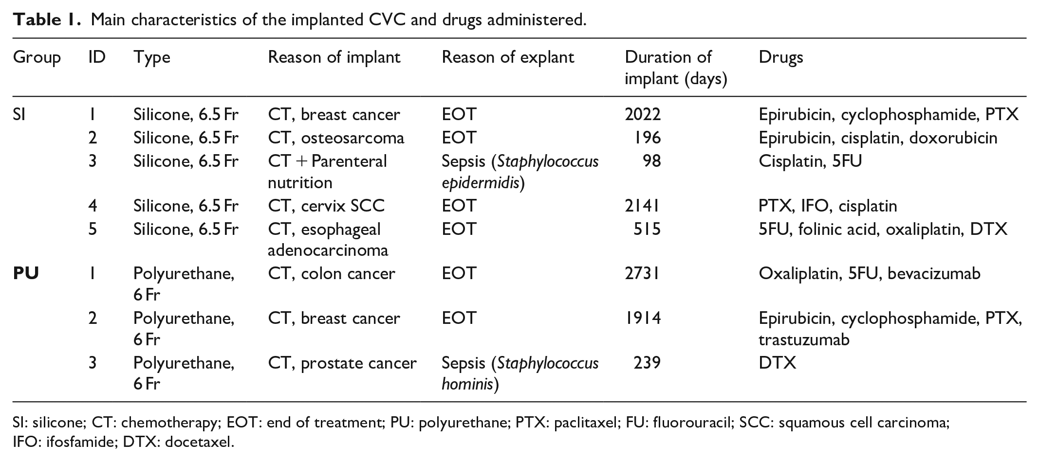
SI: silicone; CT: chemotherapy; EOT: end of treatment; PU: polyurethane; PTX: paclitaxel; FU: fluorouracil; SCC: squamous cell carcinoma; IFO: ifosfamide; DTX: docetaxel.
All implants as well as explant procedures have been performed by expert physicians within the Vascular Access Team—Anesthesiology and Pain Therapy Unit of Pisa University Hospital, Italy. All catheters had been implanted with axillary vein access in its most medial portion with an in-plane long-axis ultrasound-guided approach. The pocket had been created in the subclavicular region, without tunneling the catheter. A real implanted device is shown in Figure 1, along with a sketch showing its final positioning on the patient’s chest. For all but one patient, the reason of implant is the administration of chemotherapy (CT) for various types of cancers. For one patient, also parenteral nutrition was done besides CT. All but two implants have reached EOT. In the remaining two cases, the catheters have been removed only after 98 days for one patient in the silicone group and 238 days after implant for one patient in the polyurethane group because of infections. All the catheters evaluated in this study were non-fractured.

A real TIVAD (left) and a sketch showing its final positioning (right).
Micro-CT acquisition and analysis
Upon explantation, all CVC-Port samples have been first rinsed with saline solution and then stored at 4°C until the day of analysis. A segment of ca. 10 cm was extracted for each CVC for the imaging study. This portion was manually sectioned each time in such a way to select the CVC segment more prone to undergo mechanical stress (such as high curvature or long permanence near anatomical structures commonly associated with pinch-off). The selected segments were then cut in small segments of ca. 2 cm each to cope with the relatively short axial field of view (FOV) of the micro-CT scanner (ca. 3 cm). For each patient, a bundle of 6–7 short segments was created by wrapping them in absorbing paper, in such a way that the entire length of ~10 cm per catheter could fit in the FOV of a single scan. The bundle was formed by keeping each short segment separated than each other, so facilitating the subsequent image analysis.
All micro-CT scans were performed with the XALT tomograph 20 with the following settings: 50 kV, 0.7 mA, 1 mm Al filtration, 960 views over 360° in step-and-shoot rotation modality, 1.5 s of exposure time per view. The total scan time per sample was 45 min. All images have been reconstructed with Feldkamp-type cone-beam filtered back projection (FBP), 21 using standard (Ram-Lak) filter and embedded correction of geometrical misalignment 22 with an isotropic voxel size of 18.46 µm. Reconstructed volumes were cropped to a bounding box of 750 × 750 × 1700 voxels (x, y, z).
Catheter segments on each bundle were independently analyzed using ImageJ ver. 1.53d (NIH, Bethesda, MD, USA). 23 Morphological analysis included the main parameters having a direct effect on mechanical resistance, such as catheter wall thickness (WT), wall cross-section area (WCSA) lumen minimum and maximum diameter (LD1 and LD2, respectively), lumen cross-section area (LCSA), displacement between axes of inner and outer surfaces (AxDis), as shown in Figure 2. Catheter section geometry was assessed using the BoneJ plugin of ImageJ. 24 Besides morphology, images were used to assess the presence of radiologically identifiable defects, such as dense particles or air bubbles, inside the wall material. The presence of such local defects was scored for each catheter on a four-level scale: absent (no defects found), mild (<1 defect/cm), moderate (1–10 defects/cm) and severe (>10 defects/cm).

Conceptual scheme of the CVC cross section, with meaning of the geometrical parameters under investigation in this study. The drawing has been done with exaggerated WT variations and displacement between axes, in order to facilitate the visual understanding of the parameters.
Statistical analysis
For quantitative morphological measurements, two-tailed t test has been performed to compare each group of implanted catheters with the corresponding reference group of the same material. Differences were considered statistically significant for p < 0.05.
Results
From a macroscopic point of view, the observation of the analyzed segments of CVC did not reveal evident abnormalities, ruptures or failures. The micro-CT quantitative morphometry has shown, as expected, the different section geometry between silicone and polyurethane catheters due to the different nominal caliper (6.5 Fr for SI and SIref groups and 6 Fr for PU and PUref groups, respectively). Analysis results are reported in Table 2. The graphs in Figure 3 highlight the main morphological changes observed between implanted and non-implanted catheters, for the two materials. While comparing implanted CVC morphology with corresponding control (reference) groups, we have observed that SI group showed increased luminal cross-section area with respect to SIref (LCSA = 0.851 ± 0.020 mm2 in SI vs 0.811 ± 0.007 mm2 in SIref, p = 0.007). This change is related to the increased luminal diameter of the SI CVCs with respect to their controls (LD1 = 1032 ± 11 µm in SI vs 1014 ± 6 µm in SIref, p = 0.02). This small (<20 µm) diameter increase could suggest a drug-related erosion of the catheter material, even though we cannot exclude differences due to different batches of the catheters. We have also noticed an increased WT and WCSA in the polyurethane group as compared with the reference CVCs of the same materials (WT = 403 ± 12 µm in PU vs 382 ± 4 µm in PUref, p = 0.014; WCSA: 2.04 ± 0.09 mm2 in PU vs 1.91 ± 0.03 mm2 in PUref, p = 0.04), whereas no significant changes of the luminal diameters and area have been observed for this material. The increased thickness in implanted PU CVCs can not be only explained by the presence of biofilms, which in general have much lower thicknesses.

Main morphological parameters showing changes between the implanted group and the reference group: (a) WT, (b) WCSA, and (c) LCSA.
Results of the quantitative morphometry performed on micro-images of CVC samples.

The symbols used for scoring the local defect (dense spots or air bubbles) have the following meaning: – absent, * mild (<1 defect/cm), ** moderate (<10 defects/cm), *** severe (⩾10 defects/cm).
WT: wall thickness; SD: standard deviation; WCSA: wall cross-section area; LCSA: lumen cross-section area; LD: lumen diameter; SI: silicone; PU: polyurethane.
The WT heterogeneity, which is strongly linked to the displacement between the axes of the inner and outer surfaces (AxDis), was found to be particularly high for one silicone catheter (SI1) as shown in Figure 4. For this sample, AxDis = 74 ± 1 µm, whereas average values were 26 ± 28 µm for the SI group, 35 ± 5 µm for the SIref group, 10 ± 5 µm for the PU group and 8.3 ± 3.8 µm for the PUref group. This resulted in a high difference between minimum and maximum WT for the SI1 sample (∆WT = 127 µm). Overall, the PU group performed better than the SI group in terms of cross-section geometry uniformity.

Strong heterogeneity of wall thickness shown by the S1 sample: (a) micro-CT slice of the catheter and (b) quantitative parametric thickness map showing the local thickness at each point of the wall.
The local defect analysis showed different patterns between the two types of materials. All CVCs in this study presented hyperdense particles inside the wall. The observed (apparent) diameter of such particles ranged from 20 to 100 µm and have been found at random depths within the catheter wall. Six out of nine silicone catheters were affected by >1 particle/cm, and two of them were scored as “severe” for this type of defect. On the other hand, only few smaller particles have been found in the polyurethane group. Figure 5 shows how these dense spots are distributed in one severe case.

Severe-scored CVC for presence of hyperdense particles (S2 sample). (a) Micro-CT slice of the catheter (voxel size = slice thickness = 18.4 μm), passing through a hyperdense spot. (b) Maximum intensity projection (MIP) of the same sample in (a), integrated over 1 mm along the catheter axis, showing how frequently particles appear in the sample. (c) 3D volume rendering of the same sample, showing the hyperdense particles as red dots.
In five samples (one for SI, three for SIref and one in PU), the presence of air cavities or gaps inside the wall was detected (see Figure 6). These gaps appeared less frequently than dense particles in the observed samples. The biggest one was found in the SIref1 CVC, having a maximum diameter of 170 µm and a length of 1330 µm, as shown in Figure 6(a)–(c). All the air gaps had a random distance between surfaces and diameter >50 µm.

Biggest cavities inside the CVC wall among the samples under analysis, as found in the SIref1 sample (a, b, c) and PU1 sample (d, e, f). (a) and (d) show the transverse section of the catheters at the point of maximum diameter of the cavities; (b) and (e) show a longitudinal cross section through the same cavities; (c) and (f) are zoomed views of the highlighted rectangles shown in (a) and (d).
Discussion
Despite the preliminary nature of this study and the small number of samples analyzed, we have directly observed several signs of structural alterations in medium- and long-term totally implanted CVC, as well as in clean, never implanted catheters, using micro-CT. In this context, the term “alteration” should be interpreted as a deviation from nominal (perfect) structure of the plastic materials under use, with or without link to implant duration and chemical stress in the patient body. At the best of the authors’ knowledge, this has not been done so far. Due to the link between mechanical robustness and both local and global CVC structure, we could ask whether or not the defects under analysis may play a role in the overall mechanical robustness of the implanted device. Nevertheless, it has been recognized that the results presented here cannot provide full answer to this question, and further studies are necessary.
Indeed, unlike previous studies, focusing on global mechanical performance through load–strain curves and local geometrical parameters by means of optical and electron microscopy,25,26 this work points out the heterogeneity of geometric characteristics of CVC within the same manufacturer, model and type/duration of usage. Due to the ability of micro-CT to investigate relatively long samples at sufficiently high spatial resolution (which is not feasible with other types of microscopy), we were able to identify several local alterations in the investigated samples that could not have been spotted otherwise.
Requirements on mechanical properties of CVC must strictly adhere to the international standard ISO 10555-1;3.27,28 Structural assessments like the one performed in this study go beyond the above standard, but they can add insights on the underlying heterogeneity of the mechanical robustness of real catheters, as well as on the sources of this heterogeneity. In this preliminary study, we have not observed a different rate of occurrence of hyperdense spots in long-term implanted silicone CVCs with respect to clean ones. However, modification of this type of materials can occur over long time and it is still to be assessed by tensile strength tests the correlation between spot density and mechanical resistance. Same argument can be used for the air gaps that have shown no dependence on type and duration of implant, but in some cases reached a size which is one-fourth of the thickness of the entire CVC wall. There is of course no conclusion, from this study’s results, about which type of catheter material is better or worse from the point of view of the patient’s safety. This is in line with current experimental evidence from several investigators so far.12,14,29–31 It is indeed true that polyurethane CVCs showed more geometrical uniformity and much less granularity inside walls, even though the second biggest air bubble was found exactly on this type of material in sample PU1 (ca. 90 µm in diameter, as shown in Figure 6(d)–(f)). The biggest air cavity was instead found in the unused silicone sample, SIref1 (see Figures 6(a)–(c) and 7) with a complex shape that can only be fully evaluated in 3D (Figure 7). That cavity had a maximum diameter of ca. 150 micron in the transverse cross section and was elongated in the direction of the catheter axis for a total length of about 1.3 mm. In both cases (SIref1 and PU1 samples), the observed cavity diameters were roughly one-fourth of the catheter WT in the transverse direction. From a mechanical perspective, we cannot exclude that this type of defect may play a role in the failure process, especially during the explant procedure. Regarding the singular case of the SI1 sample, showing a consistent displacement of the lumen axis with respect to the outer surface (see Figure 4), it is also worth verifying in future experiments the impact of this WT heterogeneity on mechanical robustness. Even though none of the observed catheters in this study have undergone mechanical rupture, questions may arise on how big these defects can occur among the commercialized devices. It is undoubted that quality controls are mandatory for all medical devices, and it is known that material alterations may occur over long times. 25

Three-dimensional volume rendering of a section of SIref1 sample, including the biggest observed air cavity (dashed line) among the analyzed samples. Transverse and longitudinal sections of this cavity were shown in Figure 6(a) and (b), along with dimensional annotations.
Study limitations
Further studies on the same line of the work presented here are necessary. First of all, more samples per group must be tested, also to exclude the presence of drug-independent and duration-independent changes only attributable to the different batches of catheters in use. Indeed, due to the very limited number of samples, it was not possible to perform a real correlation test between defect number/severity and type of drug or time of implant. Moreover, catheters of each material studied in this work were bought from only one vendor (B. Braun Medical for silicone and Bard Peripheral Vascular Inc. for polyurethane): this resulted in only one type of silicone and one type of polyurethane among all the different materials in the CVC market. Hence, the results obtained cannot automatically extend to all types of SI and PU that can be found in commercial devices. Destructive mechanical testing after micro-CT imaging may help in correlating the actual role of local defects or impurities, specifically selecting those sections of catheters that are affected that local abnormalities like the ones shown in this work. Computer-based finite element modeling (FEM) could be used to simulate catheters with different amount of impurities, bubble diameter and position across the wall and lumen misalignment. Finally, micro-CT imaging of ruptured samples was not possible in our study and this might add new insights, if performed in future studies.
Conclusion
Morphological change and local structural alteration can occur in both silicone and polyurethane catheters. The clinical relevance of these findings is still to be clarified. Nevertheless, this evidence suggests the need for further studies connecting the observed morphological changes with modification of mechanical robustness, which ultimately can play a role for patient safety.
Footnotes
Declaration of conflicting interests
The author(s) declared no potential conflicts of interest with respect to the research, authorship and/or publication of this article.
Funding
The author(s) received no financial support for the research, authorship and/or publication of this article.
Ethical approval
Our study did not require an ethical board approval because the removal of PORT catheters, upon acquisition of the informed consent, was part of the ordinary tasks and workflow within Anesthesiology and Pain Therapy Unit—Vascular Access Team of the University Hospital of Pisa. This research did not interfere at all with, or required any modification to, the standard patient care procedures in our Unit, and all the data and catheter portions were treated in totally anonymous form.
Informed consent
Written informed consent was obtained from all subjects before the study.