
Abstract
Aim:
This paper provides a comprehensive review of the established concepts and newer developments related to computer-assisted implant rehabilitation.
Methods:
Two independent researchers searched the English literature published to 31st December 2023 in the PubMed/Medline database for primary and secondary research and related publications on computer-assisted implant planning, computer-assisted implant placement and computer-assisted implant restoration.
Results:
A total of 58,923 papers were identified, 198 relevant papers were read in full text and 110 studies were finally included. Computer-assisted implant rehabilitation was found to result in more precise implant positioning than freehand placement. Advantages include reduced trauma and surgery time; disadvantages include reduced primary implant stability and higher cost.
Conclusion:
Computer-assisted surgery is particularly indicated in cases of critical anatomy, but may encounter limitations in terms of cost, restricted mouth opening, visibility and adjustment of the surgical guides and the need for prior familiarisation with the procedure. Nonetheless, this surgical technique reduces the post-implant placement complication rate.
Keywords
Learning Objectives
To provide an overview of digital dentistry
To review developments and established workflows related to materials and devices used in digital dentistry
To provide practical advice on the clinical application of the computer-assisted implant rehabilitation process
To gain insight into the current trends of digital implant planning and rehabilitation
Introduction
Computerised tomography and development of interactive software to allow virtual planning, with the aim of guiding surgery precisely toward a specific target, has dramatically improved implant surgery. 1 Nowadays, patients expect both a short treatment time and optimal aesthetic results when undergoing dental implant treatment. The integrated guided implant surgery workflow helps clinicians and dental technicians to proceed to the planning of implants based on the ideal positioning of the prosthodontic restoration, while allowing delivery of the temporary or permanent restorations that meet patients’ expectations. Knowledge of the processes, tools and technologies associated with the digital dental implant rehabilitation workflow is essential for achieving high predictability and precision with implant planning. Advancements in digital dentistry have enabled the registration of three-dimensional (3D) imaging data, digital impressions, and facial scans, thereby assisting the virtual planning of dental implant prostheses. Computer-assisted implant rehabilitation aims to virtually reproduce the planned implant positions during surgery. 2
The purpose of this review is to present the current workflows related to computer-assisted implant planning, computer-assisted implant placement, and computer-assisted implant rehabilitation. Recent advancements in design and production technologies for the manufacturing of digital surgical guides are presented. Furthermore, additional data acquisition modalities such as face-scanners, virtual articulators, computer-assisted design software and jaw movement tracking devices launched on the dental market are discussed, and future trends are identified.
Materials and methods
A comprehensive electronic search of the literature on Pubmed/Medline from January 2010 to December 2023 was performed independently by two authors (DA and DN) using a standardised data collection form (Excel [Microsoft Corporation, Redmond, WA, USA] data sheet). Disagreements were resolved by a third independent investigator (GM). Search terms included “digital dentistry”, “guided implant placement”, “intraoral scanning”, and “3D printing”. Studies from the database search were screened independently by three authors (DA, DN and GM) based on title and abstract, and studies meeting eligibility criteria were read in full text. Discrepancies regarding the inclusion or exclusion of studies were resolved by discussion between the reviewing authors. Only papers in English language were included. Eligible articles included systematic reviews and meta-analyses, randomised controlled trials, prospective and retrospective clinical trials, case series and in vitro studies on computer-assisted implant planning, computer-assisted implant placement and computer-assisted implant restoration. Identified articles were retrieved and checked for additional references.
Results
A total of 58,923 papers were retrieved through the database search. Following removal of duplicate articles, identified articles were screened based on title and abstract. 198 relevant papers were read in full text and 88 papers were excluded for not meeting the inclusion criteria. A total of 110 studies met the eligibility criteria and were included in this review. The included studies have been grouped together according to the below subheadings.
The emergence of cone beam computed tomography (CBCT) in dentistry
Until the 1990s clinicians were relying mostly on two-dimensional (2D) plain film radiographic evaluation to estimate the available bone quantity for dental implant placement. To compensate for any spatial distortion the use of radiopaque spheres of known diameter was popular. 3 Conventional tomography offered an insight into the third dimension and bone sounding was a common way to get some information on the width and shape of the remaining alveolar ridge. Medical computed tomography (CT) became more available to the dental community in the 1990s, a practice boosted by the advent of specialised CT software for implant presurgical planning (Denta Scan, General Electric CT Scanning, Boston, MA, USA). 4 However, medical CT examination was expensive, imparted a high radiation dose to the patient and was not readily available to every dental practice.
A new era in dental diagnostics and in implantology emerged following the publication of the seminal paper by Mozzo et al. on a new volumetric CT device for dental imaging. 5 This was followed by the introduction to the market of a limited number of CBCT devices. The compact size, moderate financial cost, lower radiation dose and the ease of use compared to the medical CT devices led to an exponential availability of these dental CBCT devices in the dental setting. Nowadays more than 279 dental CBCT models exist provided by more than 47 manufacturers. However, differences exist in device purchase cost, hardware configuration, image quality and radiation burden. 6 The availability of CBCT devices led to the evolution of specialised software intended for implant treatment planning and for the computer-aided design (CAD) of surgical guides and prosthesis. Nowadays, 3D imaging coupled with computer-guided surgery planning is the core of the contemporary dental implant practice. 7 Last but not least, the development and availability of 3D printing introduced the notion of computer-aided manufacturing (CAM) in implant placement and restoration.8-11
In the current concept of the virtual patient, besides acquiring 3D data from the CBCT, intraoral scanners (IOS) and face scanners are used to provide the necessary datasets. All this information is then aligned to the same coordinate system. High quality CBCT data are required to facilitate the accurate alignment of the different datasets and as such to increase the overall accuracy of guided implant surgery. 12
CBCT scanning for guided implant surgery
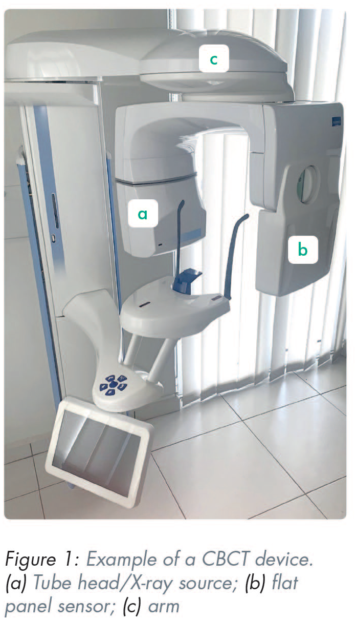
A cone beam device is compiled of three main components: an X-ray source, a flat panel sensor, and the reconstruction software (Figure 1). These components determine the image quality and eventually the expression of what are known as “artefacts” on the resulting CBCT image. A CBCT artefact is defined as any distortion present in the image that is not related to the subject studied. 13 Artefacts are a major concern in guided implantology since they commonly distort the tooth crown surface and necessitate the replacement of CBCT teeth with surfaces provided by other modalities, commonly intraoral or desktop scanners. However, this replacement of the CBCT teeth calls for the registration alignment of surface data to the CBCT data. It is at this stage (commonly referred to as “registration”) that misalignments can be expected, reducing the accuracy of the entire procedure. Since artefacts are often attributed to the patient (e.g. movement artefacts) and to the technology (e.g. noise, under-sampling, reconstruction algorithms, sensor resolution, and sensitivity 14 ), several recommendations have been made for CBCT scanning of patients with the purpose of increasing the accuracy of guided rehabilitation.8,15-17
The DICOM data
Digital Imaging and Communication in Medicine (DICOM) is the industry’s standard to transmit, store, retrieve, print, process, and display radiological data. In the realm of guided surgery, DICOM data are transferred from the native CBCT software to the third party specialised software. It must be noted that this transfer may result in data loss and image degradation. There is no easy way to identify or quantify any data loss during export from the propriety software or any image degradation during image import to the specialised implant software. Even though this probable image degradation does not seem to affect the accuracy of guided surgery, any diagnostic evaluation of the volume is advised to be completed in the native CBCT software. 18 Another challenge in DICOM data transfer is the legal requirement for keeping safe the personal information of patients. DICOM data are tagged (i.e. contain all the patient’s information the user of the CBCT chooses to add in the file) before the scan acquisition. In addition, the DICOM data can be reconstructed to depict the face of the patient, making them vulnerable to identification by specialised face recognition software. Therefore, all legal requirements for encryption and for medical and personal data privacy must be enforced during DICOM transfer either by optical means (CD or DVD) and email or by specialised online data transfer services.
The radiation burden
The preliminary preoperative and intraoperative planning for implant surgery involves 2D and 3D radiological examinations aiming to evaluate bone availability and verify the accurate placement of the implants. Post-operative radiological examination may be required when concerns arise (e.g. sinus pathology, loss of lip sensation, etc.) and additional information is required. In a recent study, digital periapical radiography imparted a mean dose of 8µSv while the average dose of the digital panoramic radiograph was 36µSv, albeit with a wide dose range (19–75µSv) between different radiological units. 19 With regard to CBCT, the commonly-cited radiation dose is in the range of 20 to 100µSv. 20 However, the doses imparted by CBCT units vary enormously, not only between the different CBCT manufacturers but also between the different imaging programs of the same CBCT model. Radiation doses from CBCT devices may reach the level of 400µSv depending on the manufacturer, the field of view (FOV) and the exposure parameters used, reaching or even exceeding the dose imparted by current medical CTs. 21
Efforts must be undertaken to minimise the cumulative radiation dose imparted to the patient, keeping the doses as low as reasonably possible. 22 Regarding CBCT it must be understood that image quality and high image resolution are always associated with higher radiation doses. 23 In guided surgery, the voxel size of 0.2mm3 is an adequate resolution serving guided surgery with low noise and a moderate radiation burden. Limiting the FOV as much as possible, minimising retakes, and using bespoke exposure parameters are additional measures that serve the purpose of reducing the radiation exposure in guided implant rehabilitation. 18
Registration of DICOM and STL datasets
In brief, a stereolithography (STL) file stores information about 3D models. This format describes only the surface geometry of a 3D object without representing colour, texture or other common model attributes. These files are typically created by a CAD programme as an end product of the 3D modelling process. STL files have an “.stl” file extension. In the dental context, STL files contain necessary information about the position of soft tissues, teeth and prosthodontic restorations. In the implant planning software, the process of combining CT/CBCT data, that is DICOM files and images from an IOS or a laboratory scanner (STL files), is performed by indicating common points. The seemingly simple process incorporates advanced technologies that, by comparing hundreds of convergent points, create consistent images. 24
In the process of data registration, the aim is to accurately combine all 3D data available to create the composite model of the virtual patient. The alignment of the STL file of the teeth to the CBCT data presents most of the challenges and it is usually the main source of errors. 25 The accuracy of matching individual images is the foundation of the precision of the surgical procedure. Computer navigation templates are planned based on two types of images: DICOM and STL. If data integration (DICOM and STL files) is inconsistent and inaccurate, this will lead to incorrect determination of the drilling axis for the dental implants.
Point registration is a semi-automatic procedure always followed by surface-based registration using the iterative closest point algorithm (automatic procedure) to implant surgery. 26
For implants placed in close proximity to vital structures, such as the inferior alveolar nerve, it is essential that the digital software user identifies the nerve, thus avoiding damage during implant placement 27 with the provision that an accurate segmentation of the CBCT data around crowns of teeth has been achieved. The purpose of segmentation is to change the representation of the image into something that is more meaningful and easier to analyse. Image segmentation is usually used to locate objects and boundaries, i.e. lines and curves in images. When applied to a stack of images, typical of medical imaging, the resulting contours following image segmentation can be used to create 3D reconstructions using interpolation algorithms. 28 The image obtained as a result of segmentation is simplified in relation to the image subjected to segmentation – this image does not contain detailed information appearing in the original image. 29 Advanced implant planning programs have built-in algorithms and various segmentation methods that aim to precisely identify vital structures that are of interest to the clinician.
Face scanning surface data can also be added using a surface registration procedure on the segmented soft tissues of the CBCT data to provide further information. Nevertheless, the accuracy of this particular alignment is not crucial for the accuracy of guided implant surgery. 30
Selection of a digital dental implant treatment planning software
Registration and alignment of different intraoral and extraoral soft and hard tissue data are achieved with the use of a dedicated implant planning software. 31 Digital dental implant treatment planning software is computer software intended for 3D virtual surgical implant placement. It is precise and can help the clinician determine the ideal implant position for a prosthodontically driven implant placement. It can also be used for diagnostic purposes and can aid in the fabrication of surgical guides for computer-guided surgery. Nowadays, there are many types of digital dental implant treatment planning software available on the market with many similarities, but also significant differences between them that give the user additional functions and possibilities. 32 These are summarised in Table 1.
Functions and possibilities of available digital dental implant treatment planning software
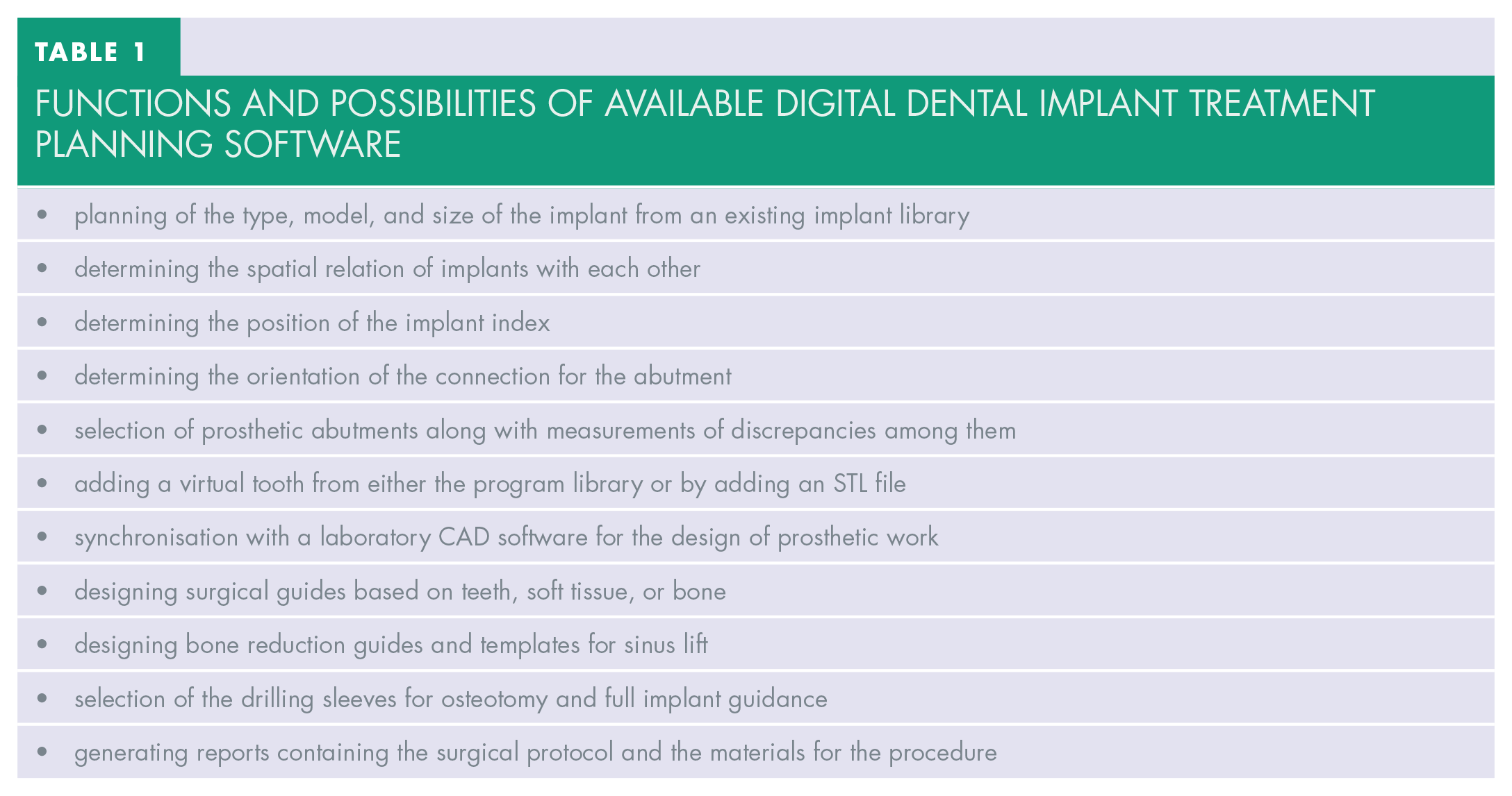
CAD software is regularly updated and has built-in implant libraries. The number of included implant systems is continuously increasing, and library updates provide greater versatility during the treatment plan. Differences in accuracy of implant placement have been reported in the literature with various implant planning software but the linear and angular deviations were ⩽ 0.32mm and ⩽ 2.63° respectively and lie within the clinically acceptable range. 33
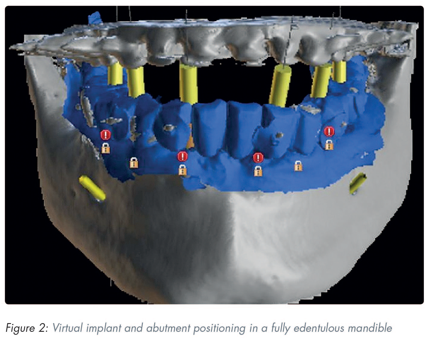
Virtual implant and abutment positioning
During implant planning and virtual placing it is recommended that the following basic rules are followed:
a minimum distance of 1.5mm between the implant and the adjacent tooth (mesial and distal)
when multiple implants are placed next to each other it is crucial to allow for a minimum distance of 3mm between adjacent implant shoulders
when the orofacial bone wall is less than 1.5mm or a layer of bone is missing on one or more sides, bone augmentation is indicated
ideally, abutments should always be loaded axially
the long axis of the implant should be aligned with the cusps of the opposing tooth
in the aesthetic zone implants should be placed sub-crestally to avoid material exposure and aesthetic problems
the ultimate treatment goal is a prosthodontically driven backward planning which will inadvertently determine the type of implant positioning and superstructure (Figure 2)
Computer-assisted implant placement
This involves the design and fabrication of the digital surgical guide. Implant surgical guides can be easily fabricated with 3D printers using compatible resin printing materials following their design using implant planning software. 34
The STL file of the implant surgical guide is exported from the implant planning software and imported into a printer-specific 3D slicing software to generate the support and initiate the digital manufacturing process. A chairside 3D printer coupled with compatible printing material can be used to fabricate the implant surgical guide. The most common printing material is a photosensitive liquid resin which has a photosensitivity that is within the wavelength range for the light source of each 3D printer. Following completion of the printing process, the surgical guide is cleaned using isopropyl alcohol 70–90% and cured under ultraviolet (UV) light with a wavelength of 385–405nm in a post-curing chamber, in accordance with manufacturer’s instructions.
The most common 3D printing technologies for the fabrication of surgical implant guides are stereolithography (SLA), digital light processing (DLP), and Polyjet™ printing (PP) (Stratasys, Eden Prairie, MN, USA). Additive manufacturing techniques are also commercially available, such as selective laser sintering (SLS), 3D printing (3DP) and fused deposition modeling (FDM) or fused filament fabrication (FFF). 35 Until recently SLA was the most common technology for surgical implant guide manufacturing, and resin guides were often called “stereolithographic guides” in the literature. 35 SLA involves a process based on the polymerisation of monomer resin by a laser beam. Following the creation of a layer, the moving platform is lowered into the reservoir tank and this process continues layer-by-layer until the printed part is completed. 36 DLP is based on vat-photopolymerisation technology, which uses a vat of liquid photopolymer resin, out of which the model is constructed layer by layer. A UV light cures or hardens the resin where required, while a platform moves the object being made downwards after each new layer is cured. The main difference between SLA and DLP is the light source. The DLP system takes advantage of a digital micromirror device (DMD) to project a mask of light that allows a layer to be cured in a few seconds. 37 PP is also based on a layer-by-layer technology. The process consists in the selective deposition of material droplets onto the building platform and their immediate solidification by a light source (usually a UV lamp attached to the print heads), allowing layers to be built up. 38 A recent in vitro study showed that the 3D printing technology (SLA/DLP/PP) has a limited impact on the accuracy of 3D printed surgical guides. However, the size of the guide can have a significant impact, as small-extent guides were more accurate than large-extent guides. 35
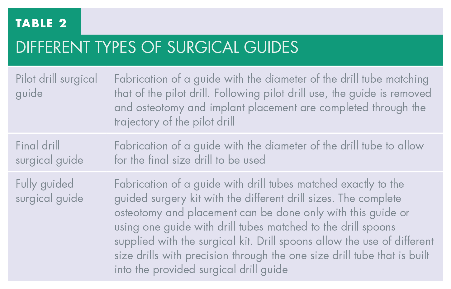
Based on the virtual planning of digital software, three different types of surgical guides can be constructed to suit different circumstances and working protocols, as shown in Table 2.
Different types of surgical guides
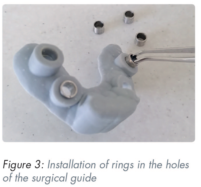
Following surgical guide printing, the installation of rings in the holes of the guide is necessary (Figure 3). The metal sleeves are located into the template and the upper edge of the sleeve should be clearly pressed against the hole in the template.
Surgical guide disinfection
A common form of disinfection of surgical guides prior to their use is with chlorhexidine gluconate 0.2% bath solution for 30 minutes. However, as research shows, this is not the most effective method and, preferably surgical guides should be disinfected in 70% isopropyl alcohol for a minimum of 15 minutes or in the case of resin guides undergo sterilisation in autoclave similar to instrument sterilisation. 39
Computer guided surgical procedure
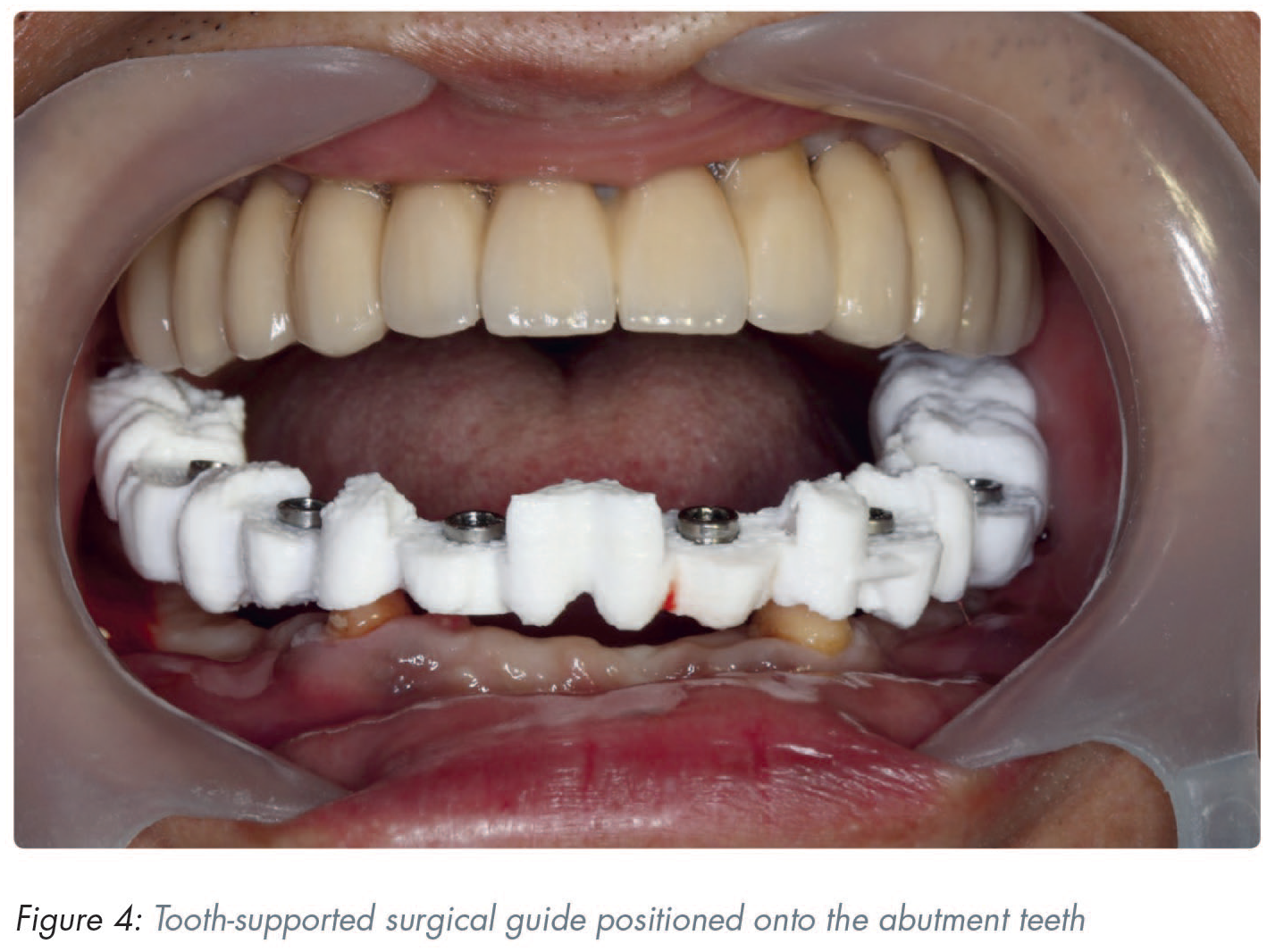
Prior to surgery, the accuracy of the surgical guide is checked for fit on the master cast. Stability of the surgical template is then tested for fit in the patient’s mouth (Figure 4). The computer aided surgical guide, via the metallic sleeves, guides the surgeon to place the implants in the virtually-planned position.
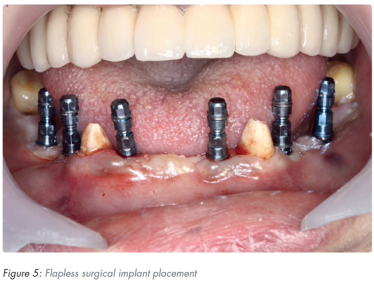
In the case where adequate keratinised mucosa is available, a flapless approach may be used (Figure 5) since no statistically significant differences have been reported for prosthodontic and implant failures, complications, implant stability quotient (ISQ) values, and marginal bone levels between the flapless and flapped technique. 40 Benefits of flapless implant placement include reduced operation time, reduced post-operative discomfort and swelling, and it has been reported to be preferred by patients who have experienced both techniques. 40
Clinical accuracy of surgical guides
Computer guided implant surgery has been reported to be more accurate than a freehand approach for placing implants into the posterior maxilla. 41
As digital guided surgery has become reproducible, the literature reveals distance deviation within 1.0mm and angular deviation up to 1.0 degree from guided implant position.42,43 However, errors can always occur between virtual planning and the surgical procedure. A meta-analysis reporting on the accuracy of guided implant surgery showed a total mean error of 1.2mm (1.0–1.4mm) at the entry point and deviation of 3.5° (3.0°–4.0°) respectively. 44 It has been suggested that a safety margin of 2.0mm should always be considered. 44
Clinical accuracy of surgical guides is affected by several factors, including errors in image acquisition, errors in orientation and cross-sectional principles, errors in surgical guide manufacturing, type of surgical guide support or guide fixation, and full versus partial guidance during implant placement.32,45
Computer-assisted implant rehabilitation
Intraoral scanning in dental implant rehabilitation procedures can be differentiated into scanning for single implant and short-spanned fixed implant supported restorations, and the scanning of the edentulous jaw with multiple implants. While the former has been established as an accurate method of conveying the position of the implant platform in relation to the soft tissues and neighbouring teeth46-49 the scanning of the edentulous jaw for an all-on-X implant rehabilitation is more challenging and conventional elastomeric impressions are still favoured by some authors.50-54
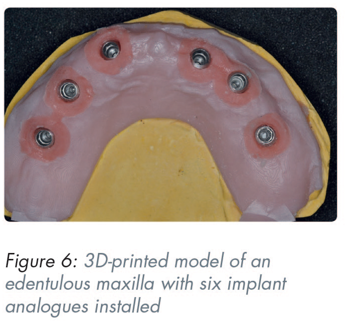
Implant positional discrepancy may occur when a physical master model is produced through additive manufacturing procedures. Discrepancies in the production of a 3D printed master model have been reported in the range of 21–56μm depending on the printer technology used 55 (Figure 6).
The transfer of the implant platform position in CAD software is accomplished through scanning so-called scanbodies that are attached onto the implants. Certain design characteristics of these transfer devices seem to contribute towards a higher scan accuracy. The material that the scanbody is made from is one of these design features, with polyether-ether ketone (PEEK) showing superior scan accuracy due to its refractory and reflective index.56,57 Scanbody length is another important factor as it allows for more precise surface capture during intraoral scanning. 58 Furthermore, a less complex, cylindrical scanbody shape has also been shown to scan more accurately.59,60
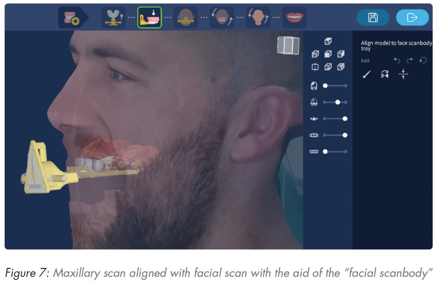
Face scanning
The primary clinical purpose of a face scanner is to aid in the correct orientation of the patient’s maxillary scan in relation to their face and lips. This will allow for realistic and facially driven prosthodontic planning. A secondary clinical purpose is to act as a virtual facebow by establishing a cranio-maxillary relationship. 61 The process requires the use of an auxiliary device, often called a “facial scanbody” to facilitate the merge between the facial and maxillary scans (Figure 7). Three different optical scanning technologies are currently used in the process of digitising patients’ facial tissue. These are stereophotogrammetry, laser scanning, and structured light scanning technologies. 62 Stereophotogrammetry devices capture surface images of the face from multiple single-lens reflex cameras and the reconstructed images can be exported in “.obj” or “.ply” formats for integration into a CAD software. However, the accuracy of these images depends on parameters such as pixel integrity and scanner resolution 63 and direct ambient light during image capturing. 64 Laser and structured light scanners, on the other hand, have different working principles. Laser scanners project a laser beam onto the surface and capture its reflection with dedicated sensors. Similarly, structured light scanners project patterned light onto the object and record its deformation with cameras. 65 Using triangulation, the X, Y, and Z coordinates of each surface point can be determined, and the 3D geometry of the face can thus be reconstructed.
Virtual articulators and jaw motion tracking devices
In order for the acquired intra- and extraoral digital data to be used in the rehabilitation process, the virtual maxilla and mandible have to be mounted in their correct 3D spatial inter-relationship and in relation to the craniofacial complex. 66 Furthermore, the dynamic movements of the mandible in relation to the maxilla must be registered. This can be achieved in a simple manner using the software proprietary to some IOS devices or by using a more sophisticated and expensive jaw tracking device. Additionally, the inclusion of bone data acquired with a CBCT device to this data pool set can lead to the formation of the virtual patient. 67
Virtual articulators are software tools incorporated into CAD suites 66 (Figure 8). There are currently two types of virtual articulators available: the completely adjustable and the mathematically simulated-average value articulator. 68 The virtual completely adjustable articulator requires a jaw tracking device to accurately capture the exact dynamic mandibular movements, a digital counterpart to the analogue fully-adjustable articulator. The virtual mathematically simulated articulator, on the other hand, only requires dialing in a few additional settings in the software (inter-condyle distance, sagittal condyle inclination, Bennet angle) to be able to reproduce mandibular movements, much like an analogue semi-adjustable articulator. 68
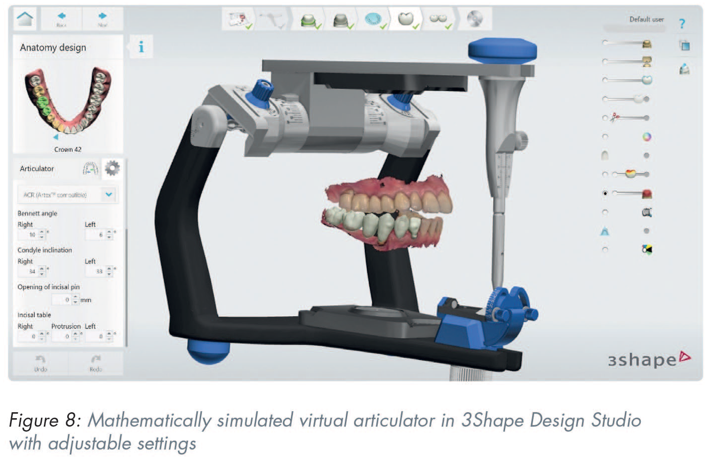
A key step in the virtual mounting process is accurate recording of the maxillomandibular relationship either directly using an IOS or indirectly by taking conventional impressions, mounting the physical casts onto an articulator and digitising the occlusion. The direct intraoral digitisation of the occlusion has been shown to be as accurate as the indirect method69,70 but its deviation can be influenced by the amount of pressure the patient exerts when in intercuspal position, 71 the location of teeth and the width of the area scanned,72,73 the available interocclusal space 74 and the bilateral or unilateral acquisition. 75
Conclusion
Digital dental implant rehabilitation workflows consist of several steps with varying degree of difficulty. As with all techniques in dentistry, caution must be applied by the operator to minimise the procedural errors. Acquiring an accurate set of DICOM data from a CBCT device is currently considered core practice for the initiation of the implant planning sequence. Accuracy can be increased with the use of metal artefact reduction algorithms that are available within the software of most CBCT devices. Proper volumetric, intraoral and extraoral surface data alignment is the second important step in the process and careful choice of an appropriate virtual implant placement software is recommended. Also, manufacturer’s instructions must be followed during the design and production of the surgical guide.
In the final rehabilitation stage, indications and limitations of novel technologies such as intraoral scanning, face scanning and jaw movement tracking must be respected.