
Abstract
This research predicts the performance and failure mode of a developed tenoning jig (TJ) used on the circular saw machine. TJ developed consisted of a double-based adjustable medium density fibreboard (MDF) with an area of 100 × 200 mm2, side panel of equivalent length and a height of 114 mm2. SOLIDWORKS software, 2021 was used to model and simulate the jig applying a static load of 500 N. The jig performance was evaluated, results were recorded and deformation shape presented in true and defined scale of 1160.89. The analysis shows maximum directional deformation at 2.342 × 10⁻² mm, equivalent elastic strain at 1.245 × 10⁻⁴, stress and yield strength at 2.580 × 10⁶ N/m2 and 3.930 × 10⁷ N/m2, respectively, with the factor of safety at 15. The jig offers cost-effectiveness with an estimated manufacturing cost of US$43.123 as of 2021. This research enhances safety in circular saw operations, minimising risk and improving the overall woodworking process.
Introduction
Background
In the pursuit of efficiency and productivity, the evolution of machines has revolutionised various industries, allowing tasks to be completed with minimised energy consumption and accelerated speed.1–5 Before the advent of machinery, human labour relied solely on physical power, which proved inefficient.6,7 Throughout history, the quest to reduce labour-related energy expenditures has driven the invention of increasingly sophisticated tools, from rudimentary hammers and screwdrivers to contemporary, computerised machines powered by electricity and combustion engines.4,5,8 While industrialised nations enjoy access to cutting-edge automated devices, a stark contrast exists in underdeveloped regions where importation costs often restrict access to advanced machinery.9–11 Consequently, local industries resort to outdated equipment imported from other countries or attempt to fabricate makeshift solutions within their limited financial means.12,13 Like many others, the woodworking industry heavily relies on machines to facilitate and streamline various processes. 14 A diverse array of stationary and portable woodworking machines, such as circular saws, band saws, and jointers, has been developed to address specific tasks.15,16 Nevertheless, the versatility of these readily accessible machines is often constrained, necessitating the search for more efficient and effective approaches to various woodworking activities. 17 Jigs, ingeniously crafted devices, have emerged as valuable companions to machines, enabling them to perform tasks beyond their original design.18–20 These purpose-built tools not only enhance accuracy and expedite task completion but also ensure uniformity in producing complementary components.17,21
At the heart of woodworking machinery lies the circular saw, an indispensable tool for transforming planks into dimension lumber, catering to a myriad of applications.15,22,23 Circular saw machines excel in ripping and crosscutting operations on flat plank surfaces, yielding square or rectangular pieces.24,25,26 Moreover, these versatile machines can be employed for specialised tasks such as re-sawing and cutting dadoes and rabbets.27,28 Among the critical challenges in circular saw operations is the creation of precise tenon joints – a common woodworking joint used in furniture and cabinetry construction.17,29 Achieving accurate tenoning on a circular saw machine can be a formidable task requiring a precision tool like a tenoning jig. A tenoning jig is an ingeniously designed accessory tailored to ensure accurate and safe tenon operations with a circular saw. This specialised jig securely holds the workpiece and guides it through the circular saw, resulting in precisely cut tenons. 20 Beyond safety, the tenoning jig significantly enhances efficiency by delivering consistent results, enabling woodworkers to effortlessly craft repeatable and uniform tenons. 30
While the tenoning jig promises precision and safety, the complexities of predicting its performance and potential failure modes have posed challenges that have, until now, relied heavily on intuition and experience.19,20 As only large manufacturing companies in developing countries have the knowledge and resources to apply modern methods, woodworkers and engineers alike have come to understand that the performance and reliability of this crucial accessory are not to be taken for granted. 31 Thus, the tenoning jig's performance, as well as its potential failure modes, represent critical factors that directly impact the quality and safety of woodworking endeavours. 30 In response, our research endeavours to introduce predictive modelling and simulation as powerful tools in comprehending the behaviour of the tenoning jig within the context of circular saw operations.32,33 Through this innovative methodology, we aim to not only forecast the jig's performance but also unravel the enigma of potential failure modes that have long eluded traditional methods. 32
This research represents a convergence of tradition and technology, craftsmanship and computation.31,34 It is an exploration of how predictive modelling and simulation can enhance our understanding of the tenoning jig's behaviour under varying conditions and loads.31,32 The ultimate goal is to empower woodworkers and manufacturers with insights that transcend the boundaries of intuition, enabling them to craft with precision, optimise with confidence, and work with unwavering assurance in the reliability of their tools. As we embark on this journey into the heart of woodworking innovation, we recognise that tenoning jig's story is intricately linked to the broader narrative of technological progress. Through the lens of modelling and simulation, we aim to craft a future where precision, efficiency, and safety seamlessly blend, enriching the world of woodworking with newfound possibilities.
Outline
This article presents an experimental and numerical investigation of a tenoning jig. Detailed design and fabrication of the tenoning jig were carried out. Five different species of wood with varying densities (Khaya grandifoliola, Ficus mucuso, Funtumia Africana, Celtis mildbraedi, Albizia lebbek) were tenoned. Visual evaluation was conducted during machining and on the finished tenon for a precision cut. The maximum force applied in the cutting process was estimated and the result was used during the finite element (FE) simulation process. Two different scales were presented with the FE models to portray performance and failure mode.
Materials and methods
Materials
The materials used in this study were medium-density fibreboard (MDF) available within the environs of the research area (Calabar, Nigeria). The bolts used in the study were M10 and M4 end-to-end bolts with their hand-fabricated knobs. The screw used in this study was a gb-recessed cisk wood screw made of steel. Figure 1 shows the pictorial view of the designed tenoning table jig. A detailed drawing and an exploded view of the jig is shown in Figures 2 and 3, respectively. The specific configurations of the tenoning jig are also presented.
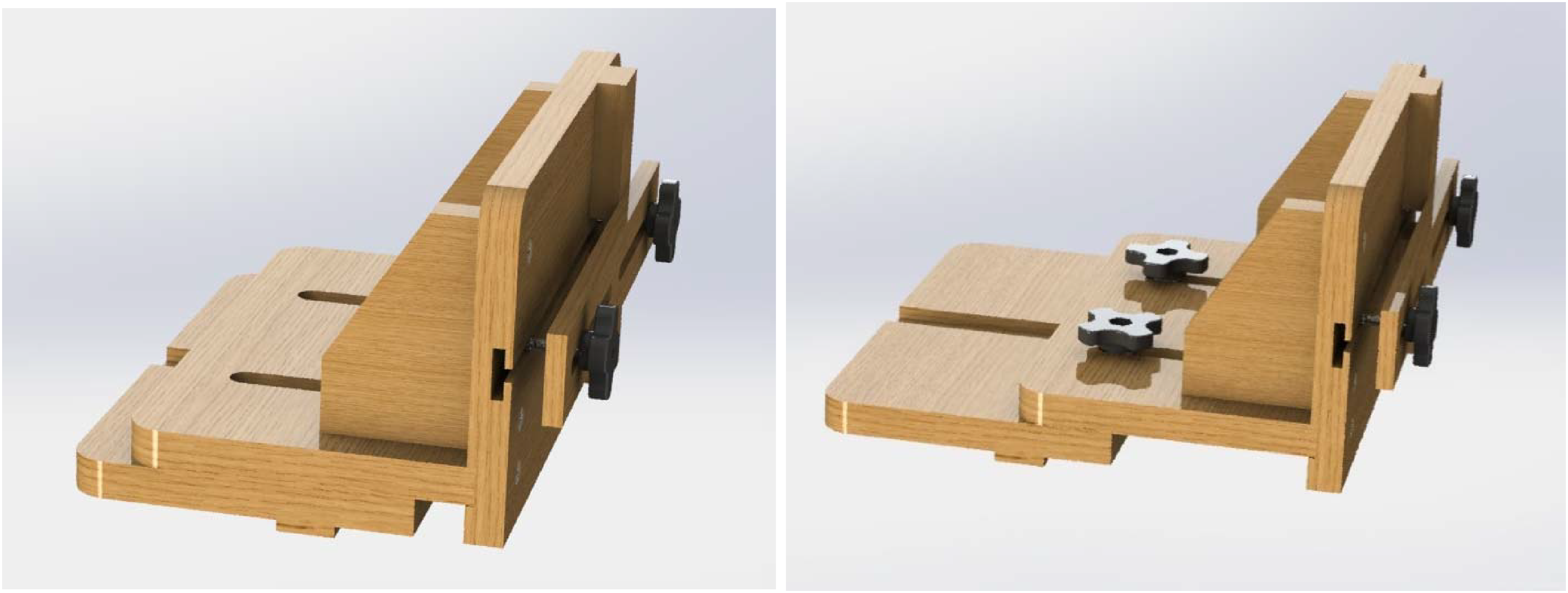
Pictorial view of the designed tenoning jig.
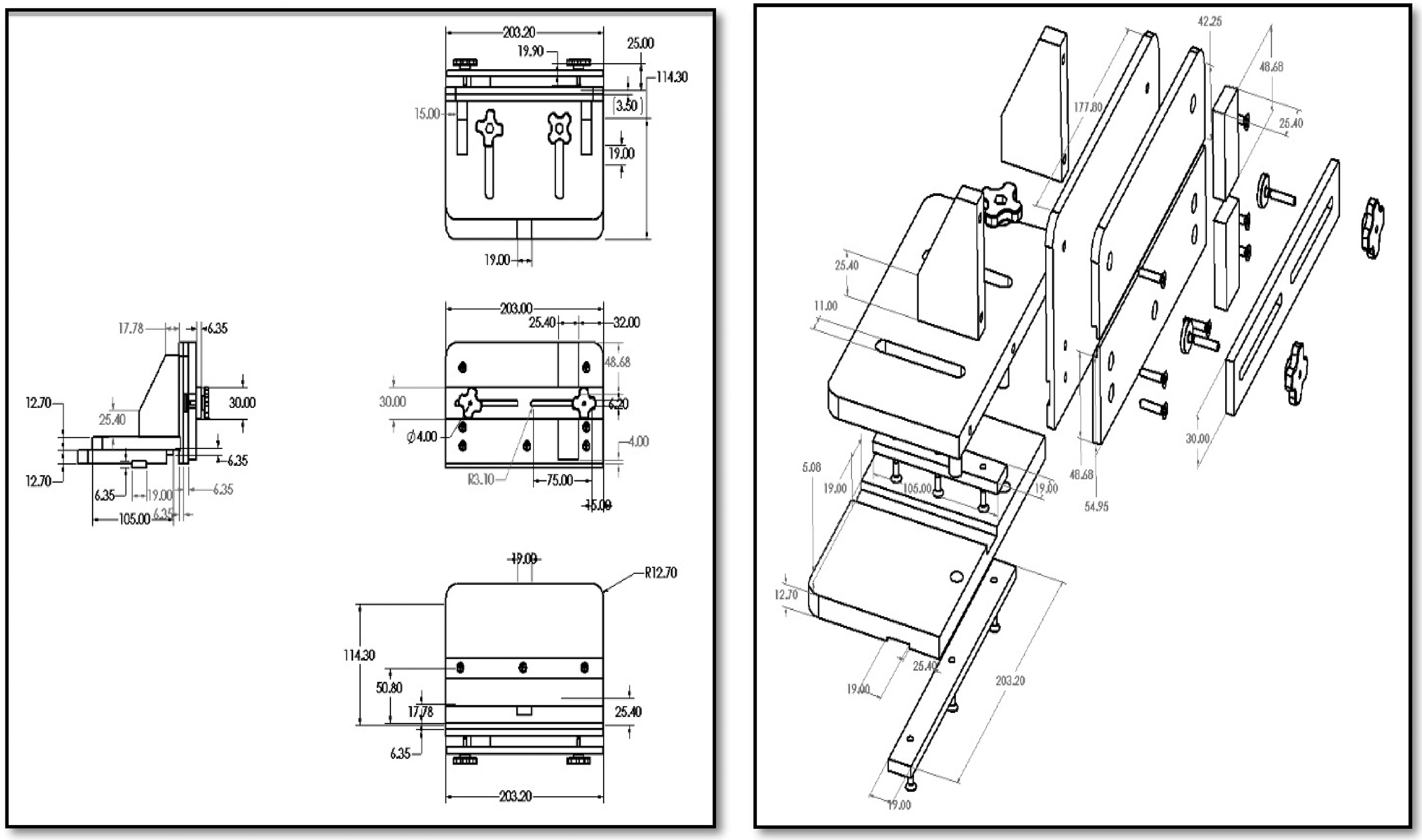
Detailed drawing of the designed tenoning jig.
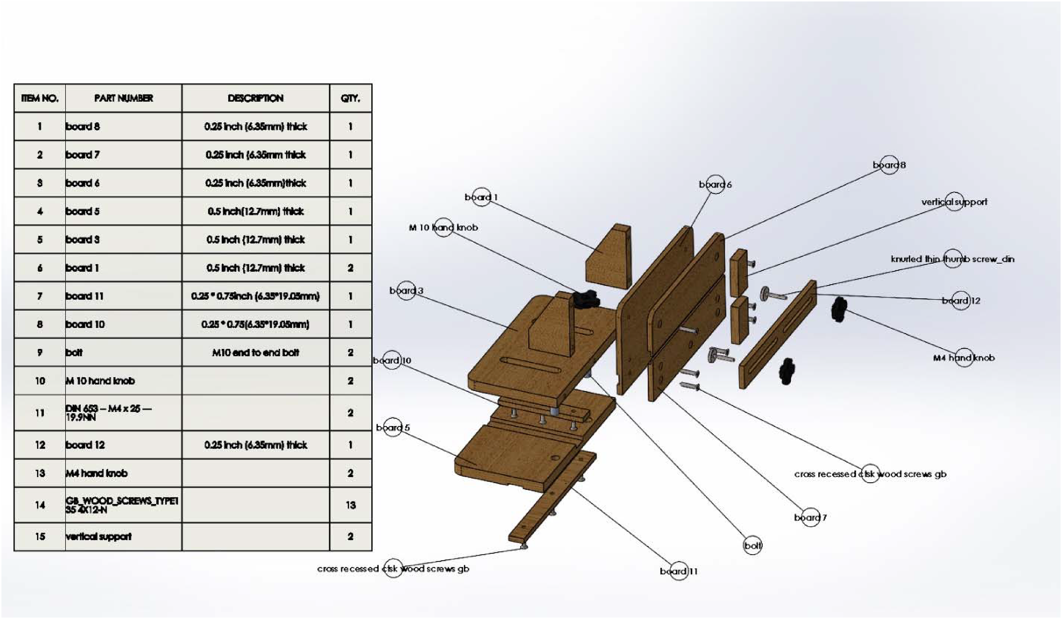
Exploded view of the designed tenoning jig.
Design considerations
The tenoning jig's design took into account estimates for the fasteners’ resistance, screw-holding ability, and loading capacity. The fastener design processes outlined in Forest Products Laboratory's General Technical Report from 2021 were adhered to.
Bolts
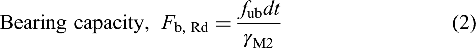
The shear and bearing capacity under the bolt was computed using the formula of Seward.
35
Screws
Tapping screws were commonly used in areas where withdrawal strength was important.
36
Care was taken when tightening screws in the particleboard to avoid stripping the threads. The maximum amount of torque that was applied to a screw before the threads in the particleboard were stripped is given by
37

Equation (3) is for 8-gauge screws with a depth of penetration of 15.9 mm. The maximum torque is fairly constant for lead holes of 0% to 90% of the root diameter of the screw.
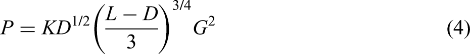
Ultimate withdrawal loads P (N) of screws from particleboard was predicted by the equation given in USDA Wood Handbook (2021).
38
Cutting force
The cutting force of the circular saw machine was determined in accordance with Bershadskiy and Tsvetkova's.
39
formula as cited by Vlasev.
40
The tangential force of cutting was calculated by the equation
40
:

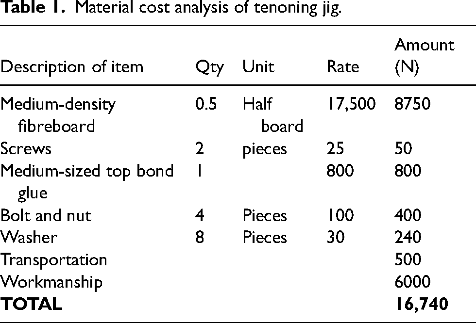
Costing of production
The materials used for the fabrication of the tenoning jig were estimated from the list produced by the design software (Figure 3). Table 1 shows the cost of fabricating the tenoning jig. The jig cost a total of sixteen thousand, seven hundred and forty naira (N16,740.00) an equivalent of US$43.123 as of 2021. This shows that the tenoning jig is cost-efficient and affordable to woodworkers with an interest in fabricating the circular saw machine.
Material cost analysis of tenoning jig.
Fabrication of tenoning jig
Materials for the fabrication of the tenoning jig were sourced from the local wood market within the research location and taken to the University Wood Products Engineering workshop for the fabrication process. Full-size MDF with dimensions of 2240 × 1220 × 18 mm were first cut and processed into the final shape with dimensions as specified in the design (Figure 2). Holes for bolts and knobs were drilled as detailed. Finally, the jig was assembled using an electric driver. Screws were driven into the blocks perpendicular to the face to ensure the screw threads were fully inserted into samples.
Experimental evaluation
Figure 4 illustrates the setup of the tenoning jig on the circular saw machine. The force exerted is positioned in the rotating direction of the saw blade as it comes in contact with the workpiece. Five samples of different wood species 50 × 50 × 400 mm (Khaya grandifoliola, Ficus mucuso, Funtumia Africana, Celtis mildbraedi, Albizia lebbek) were tenoned to test the precision of the tenoning jig on the circular saw machine using visual observations and measurement tape. The jig was also observed for signs of possible failures. All observations were recorded.
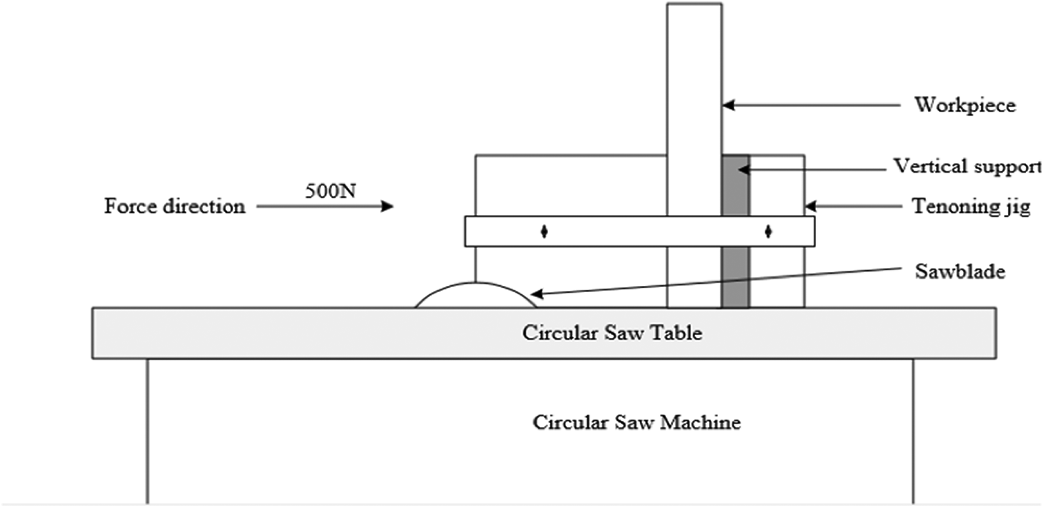
Experimental setup of the tenoning jig on the circular saw machine.
Finite element modelling
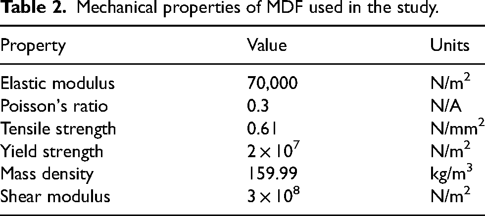
Figure 5 shows the 3D finite element model (FE model) established in this study for simulating the tenoning jig's performance in a CSM, which was closer to the real condition of the experimental evaluation. The simulations were conducted in the FE Solidworks 41 software interface. The mechanical properties of MDF as listed in Table 2 29 were specified for the FE model. Connection for the tenoning jig was assigned as bolts and nuts as shown in Figure 3. In this model, the base in the yz-plane is assigned a fixed geometry as an anchored point, to resemble the experimental setup in Figure 4. Because the tenoning jig's bar is slotted into the table's groove, it acts as a fixed support for the tenoning jig. The displacement load was applied in the direction of the moving blade towards the vertical support until the maximum magnitude was reached (Figure 4). The tangential behaviour of the interaction contacts between the cutting blade and the timber part was defined as surface-to-surface contact with finite sliding. The friction coefficient has been assumed to be equal to 0.33. 42 The mesh density of the wood-based sample was approximately 1.4 mm. Two types of FE models were created in this work. The first represents the true scale of deformation while the second was at a defined scale of 1160.89 to reflect failure modes. The von Mises equivalent stress and the maximum reaction force at the reference point of the applied load were outputted.
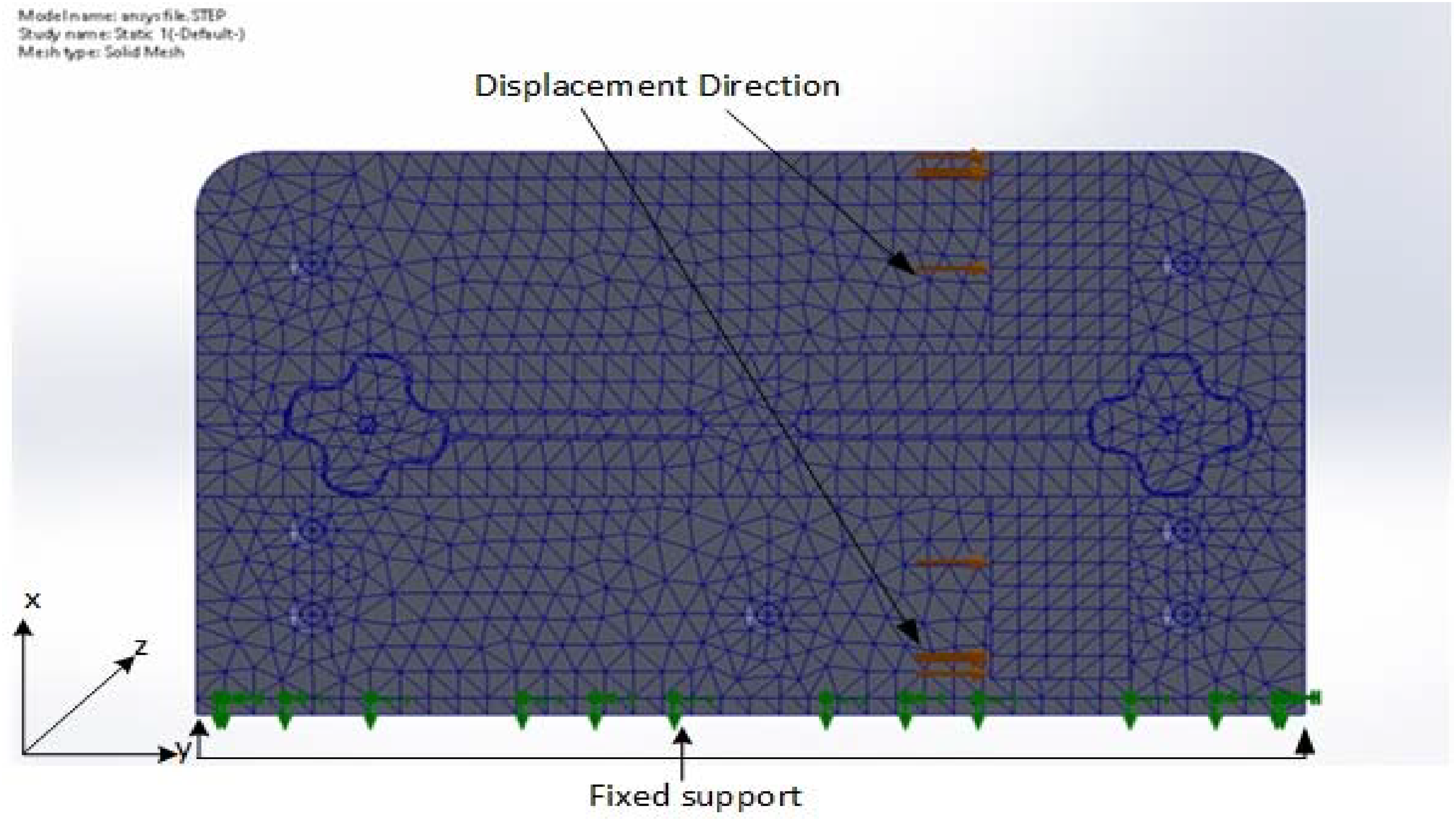
Mesh and boundary conditions in the numerical model.
Mechanical properties of MDF used in the study.
Results and discussion
Fabrication and evaluation of tenoning jig
The tenoning jig as shown in Figure 7 was easy to fabricate using simple and portable tools. It is observed that applying the design methods according to DeCristoforo 20 and Capototos, 17 produced satisfactory results. For easy screwing, an improvised method was used to fabricate the knobs for the bolts as shown. Figure 6 shows samples of tenon joints produced using the tenoning jig on the circular saw machine. The evaluation process done in the University Departmental workshop using the circular saw machine examined during the design process was safe and improved the overall woodworking process. Figure 7 shows the finished jig mounted for use on the circular saw machine. The jig was observed to support the user adequately and satisfactorily after the evaluation process.
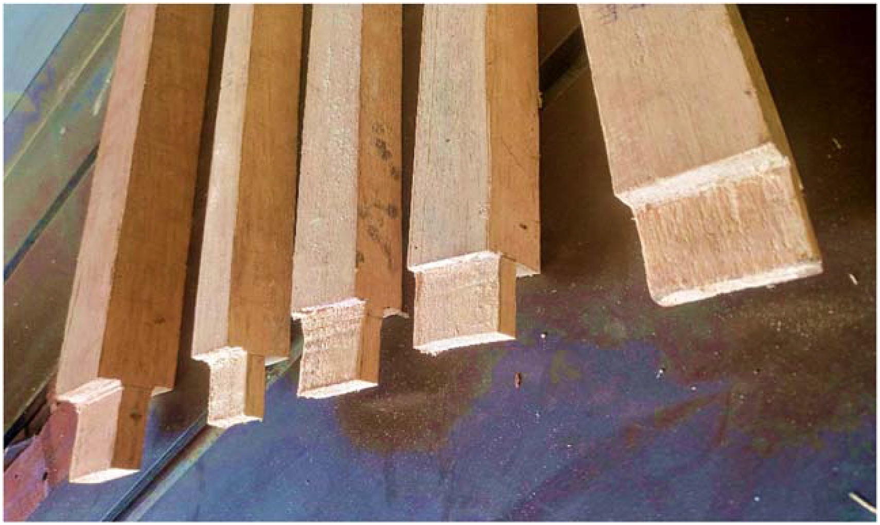
Samples of tenon joints produced using the jig on the circular saw machine.
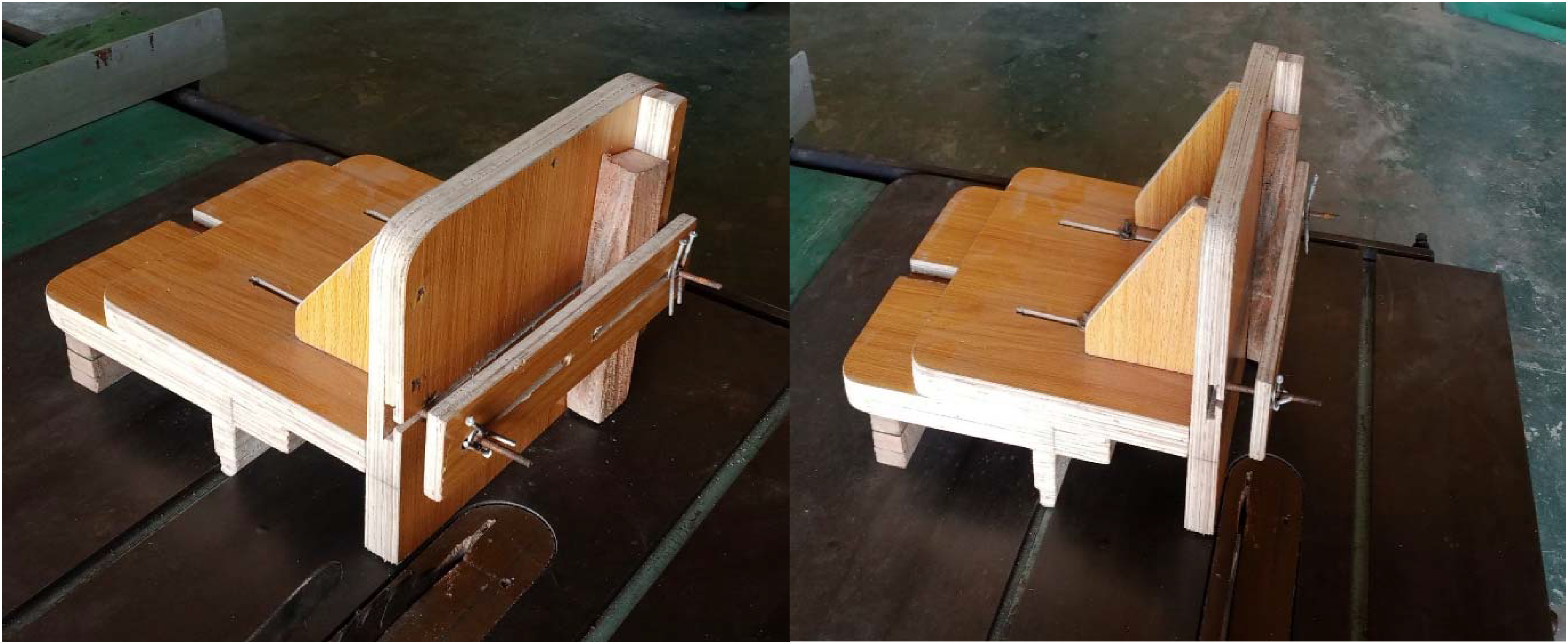
Evaluation process of the tenoning on circular saw machine.
Simulation analysis of the sliding table jig
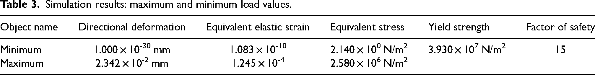
Table 3 presents data from the simulation analysis carried out on the modelled tenoning jig when a load is applied. The directional deformation, Elastic strain equivalent and equivalent static stress are presented at minimum and maximum levels. The yield strength and factor of safety are also presented in the table. The directional deformation values of the tenoning jig which indicates the amount by which the object deforms or changes shape in a particular direction range from a minimum of 1.000 × 10⁻³⁰ mm to a maximum of 2.342 × 10⁻² mm. The equivalent elastic strain values of the tenoning jig which measures the ratio of deformation to the original length of the jig and provides an indication of its elasticity range from a minimum of 1.083 × 10⁻¹⁰ to a maximum of 1.245 × 10⁻⁴. The stress experienced values of the tenoning jig which indicates the internal forces acting on the jig, resulting from external loads or deformation range from a minimum of 2.140 × 10 N/m2 to a maximum of 2.580 × 10⁵ N/m2. The yield strength of the tenoning jig, which is the maximum stress it can withstand without permanent deformation or failure is 3.930 × 10⁷ N/m2. The factor of safety associated with the tenoning jig is given as 15.
Simulation results: maximum and minimum load values.
Stress distribution
Figure 8 shows the von Mises stress distribution around the simulated FE model when exposed to external loading. Stresses are observed to be higher at the vertical support where the force is directed and the workpiece is wedged, the base slot and the lower parts of the fence. Other areas were observed to have minimal distribution levels of stress.
Stress distribution on tenoning jig.
Strain distribution
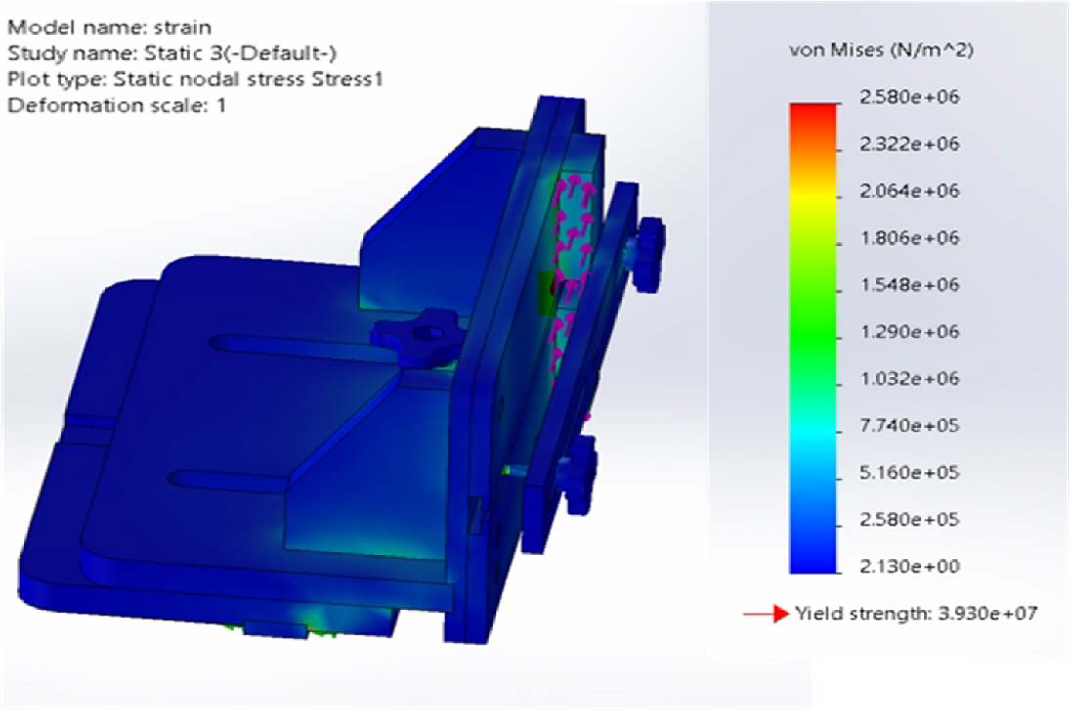
In Figure 9, the elastic strain distribution around the simulated FE model is depicted when subjected to external loading. The strain distribution appears to affect the same areas where the stresses were displaced but with more prominence. The bolted knob is also found to share in the strain distribution. However, minimal levels of stress distribution were observed in other areas.
Strain distribution on tenoning jig.
Displacement distribution
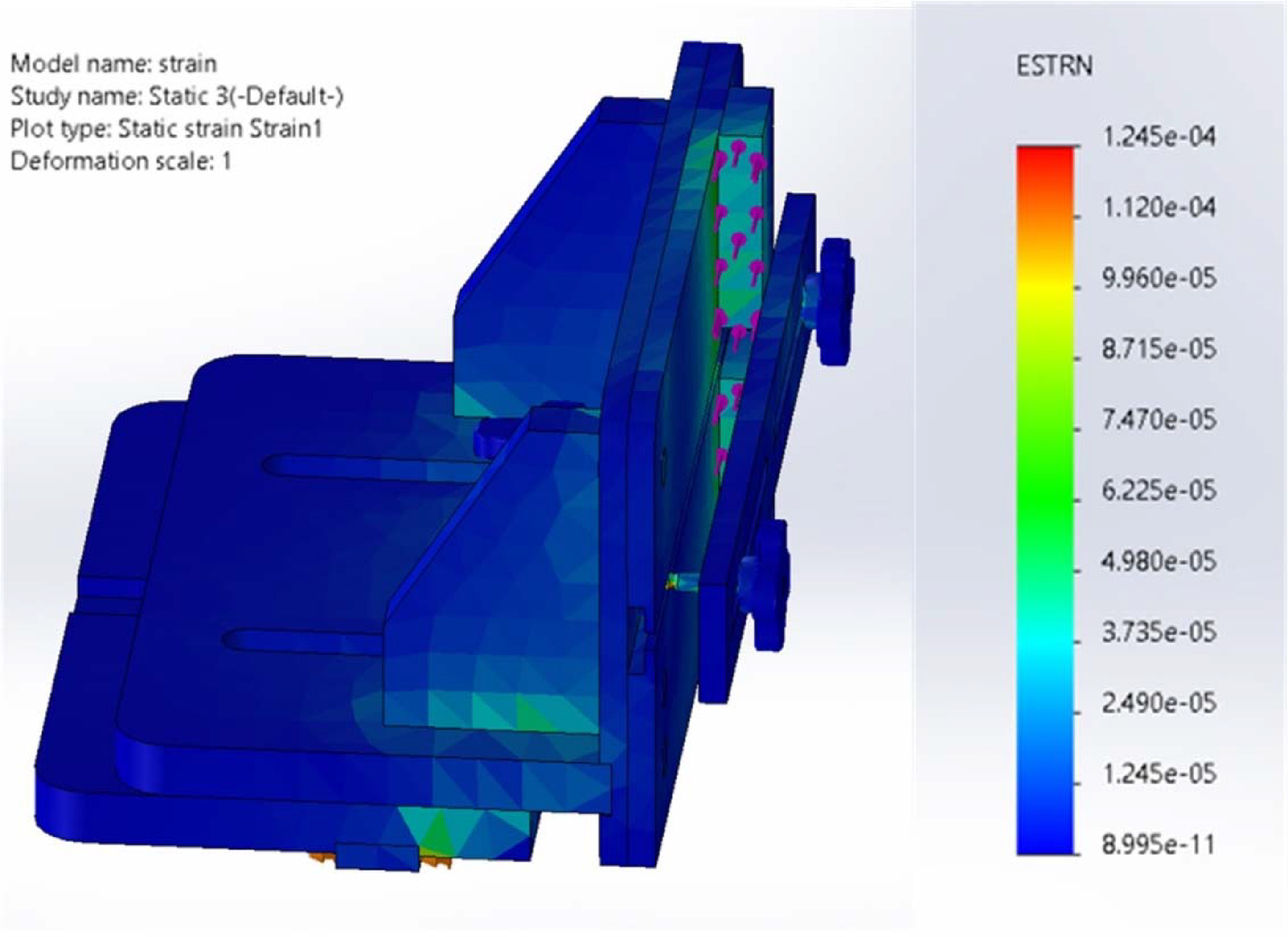
Figure 10 shows the displacement distribution analysis on the simulated FE model when an external load is acting on it. The distribution is observed to be highest at the upper part of the vertical support at over 2.108 × 10⁻² mm spreading directly to the fence and fence bracers on both sides within the range of 9.368 × 10⁻² mm to 1.639 × 10⁻² mm. The clamp absorbs a fair part of the distribution up to 2.108 × 10⁻² mm, leaving an even distribution on other parts as low as and below 1.000 × 10⁻³⁰ mm.
Displacement distributions of tenoning jig.
Failure modes
To observe a physical deformation on the FE model tenoning jig, the stress, strain and displacement diagram were scaled to 1160.89 as shown in Figure 11a, b and c. This simulation shows a deformation of the fence. However, it should be noted that the true scale (Figures 8, 9 and 10) represents the possible deformation that can occur on the jig.
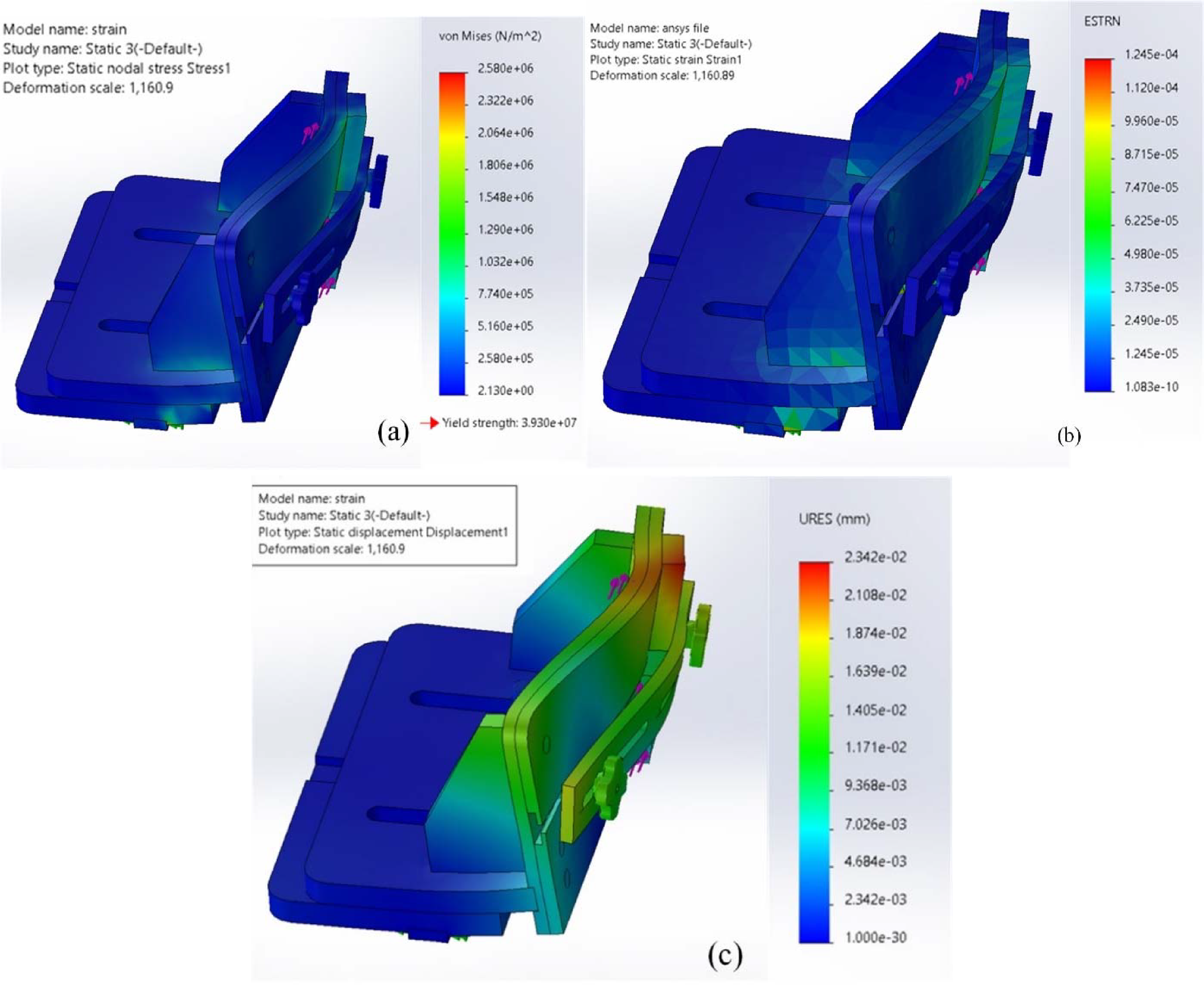
Prediction of failure modes in FE model (a) stress, (b) strain and (c) displacement when scaled to 1160.89.
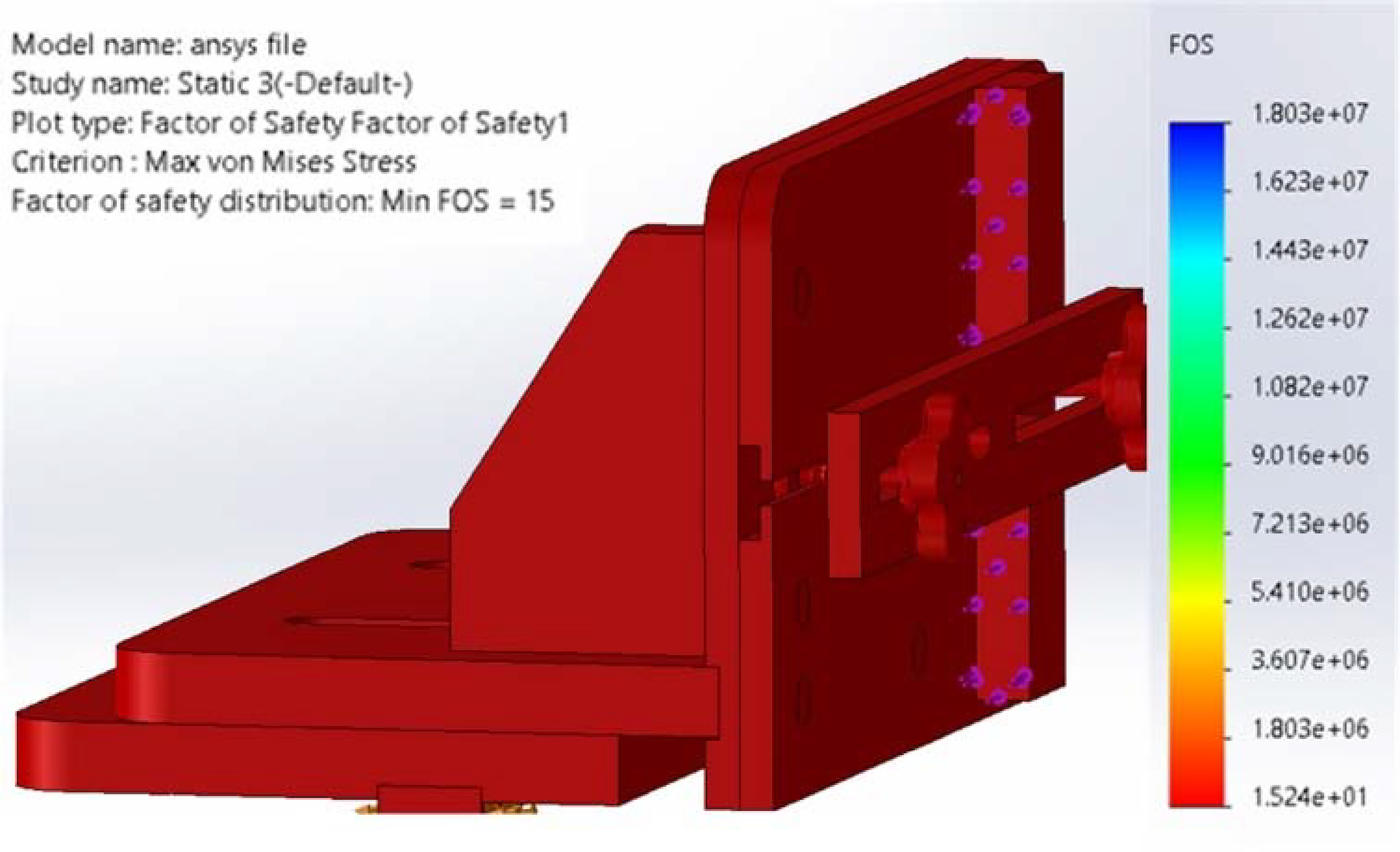
Factor of safety
Figure 12 shows the factor of safety value on the simulated FE model when an external load is acting on it. The factor of safety at maximum is 15, which means that the jig as designed can withstand loads that are 15 times higher than its designed load.
Factor of safety.
Conclusion
Modelling and simulation of a tenoning jig to predict performance and failure mode on a circular saw machine was presented in this study. The following conclusions were drawn:
The tenoning jig improves the usage, and safety of the circular saw machine thereby encouraging the development and safe use of locally made circular saw machines. The finite element model (FE model) applied to simulate and analyse the behaviour of the tenoning jig could be used in wood-based materials. The FE model can reflect the stress distributions on the tenoning jig, which was also used to predict the failure mode of the jig. Thus optimise the design where necessary.
Future works should focus on developing and simulating more jigs to perform other operations on woodworking machines. The tenoning jig is affordable, easy to apply and can serve other purposes such as teaching and research, thereby enhancing economic development. The findings of this study contribute to the advancement of woodworking equipment and promote efficient and safe practices in the industry.
Footnotes
Declaration of conflicting interests
The authors declared no potential conflicts of interest with respect to the research, authorship and/or publication of this article.
Funding
The authors received no financial support for the research, authorship and/or publication of this article.