
Abstract
Tall timber buildings are prone to serviceability problems (e.g. lateral displacements and wind-induced accelerations). This article investigates the feasibility of timber outrigger system to build up to 20 storeys using linear elastic finite element analysis and relevant European and international standards such as EN 1990, EN 1991-1-1, EN 1991-1-4, EN 1995-1-1 and ISO 10137. The location of up to two outriggers was optimised based on different serviceability criteria. Various outrigger layouts were investigated, and their stiffness demands were discussed. The efficiency of outrigger structures in reducing lateral displacements and wind-induced accelerations is highlighted. A feasibility study considering serviceability requirements was performed using different basic wind velocities, number of storeys and gravity loads. Although the focus of the article is on serviceability requirements, some ultimate limit state considerations (forces and stresses) were briefly discussed. The results demonstrate the feasibility of building up to 16 storeys under medium to high wind velocities.
Keywords
Introduction
The increase in world population results in higher urbanisation. On the other hand, the construction industry is a major contributor to greenhouse gas emissions worldwide. 1 The increased urbanisation can further increase greenhouse gas emissions which have unfavourable impacts on the environment. Therefore, the use of sustainable building materials is of great importance. Timber is a renewable material that can serve as an alternative to concrete and steel to reduce the environmental impact of construction. Eliassen et al. 2 performed a comparative study using life cycle analysis (LCA) and concluded that using timber can reduce greenhouse gas emissions by more than 13% compared to reinforced concrete and steel. Another LCA study by Skullestad et al. 3 on buildings up to 21 storeys showed that timber buildings have 34% to 84% lower climate change impact than reinforced concrete buildings with similar load-carrying capacity.
Timber buildings, due to their lightweight and moderate stiffness, are often susceptible to excessive accelerations and lateral deformations under wind loads.4–13 Excessive accelerations can cause occupants discomfort, and excessive lateral deformations can cause damage and may influence the functionality of the building. The acceleration due to wind can be reduced by increasing the building's mass, 10 damping, 14 lateral stiffness, 13 or a combination.
Several structural systems can be used for multi-storey timber buildings. Cross-laminated timber (CLT) is commonly used for multi-storey timber buildings, for example the 9-storey residential building Stadthaus in London. 15 However, such structures are usually cellular and may not be architecturally spacious. Braced structures are also prevalent in tall timber buildings. Global diagonal bracing was successfully employed in Treet (14 stories) 16 and Mjøstarnet (18 stories) 5 in Norway. The use of such structures requires large diagonal elements running along the full height of the building, affecting aesthetics and architecture flexibility. Moment resisting timber frames (MRTFs) 17 provide good architectural flexibility. MRTFs achieve lateral stiffness by means of semi-rigid beam-to-column connections. Vilguts et al. 4 performed a parametric analysis on MRTFs and suggested that such systems can be used up to 8 storeys with 2.4 m spacing between adjacent frames.
Outrigger (OR) structural system has been used in many concrete, steel, and composite tall buildings around the world.18,19 High-rise buildings usually incorporate a central elevator core(s) together with walls and columns. Outriggers are stiff horizontal structural elements that connect the building's core/wall to the exterior columns.20,21 The use of outriggers couples the core, walls and columns, resulting in a higher lateral stiffness and thus increases the possibility of building taller buildings.20,21 The structural behaviour of outrigger structures is illustrated in Figure 1. When the central core/wall deflects laterally under lateral loads, a tension-compression couple is generated in the exterior columns, resulting in a restoring moment at the outrigger level. The restoring moment at the outrigger level reduces the lateral displacement and the bending moment at the central core/wall.
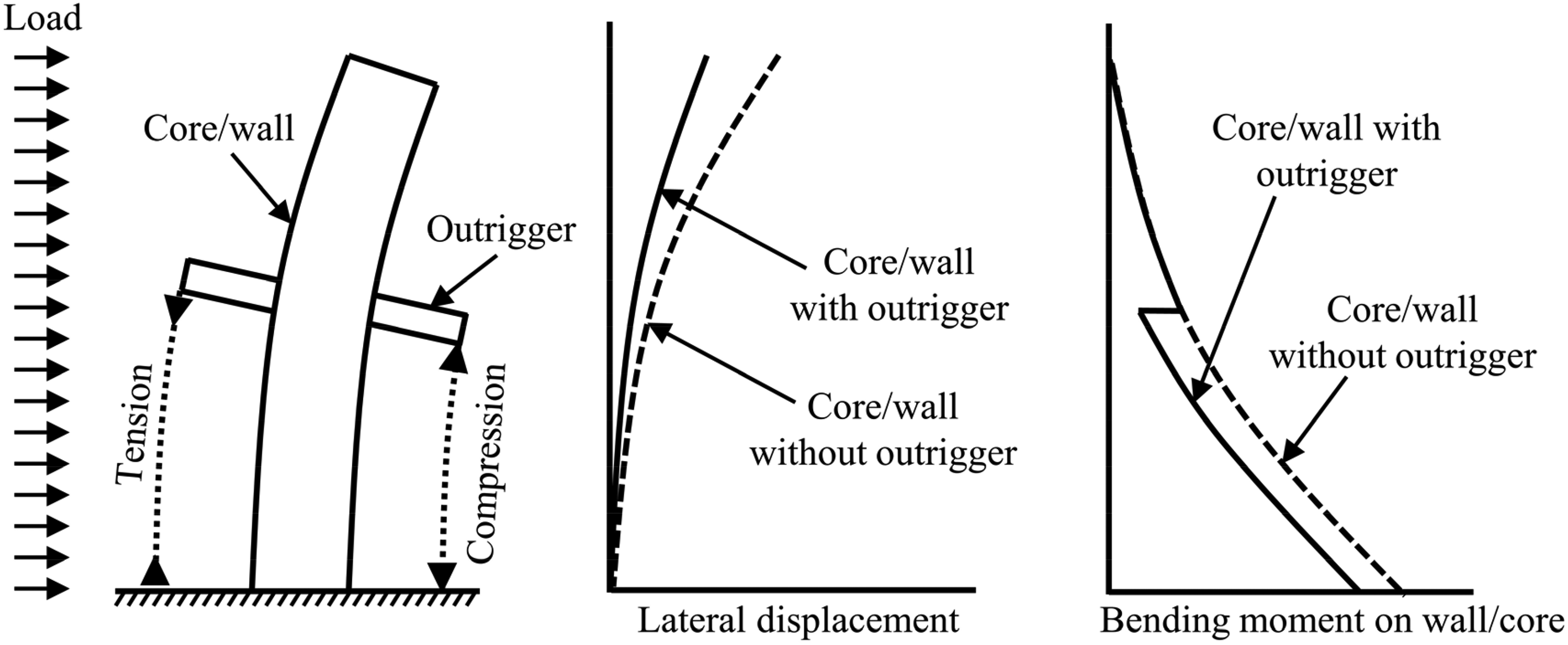
Structural behaviour of outrigger structural system. 22
The location of outriggers is important and greatly influences the structural behaviour. 22 Typically, the location is coordinated with the architect, considering that the presence of an outrigger imposes architectural constraints on the respective floor. Several studies have investigated the optimum location of outriggers.22–28 In these studies,22–28 the optimum location was selected mainly to achieve smallest lateral displacements. The optimum location of the outrigger depends on the structural characteristics of the building, 22 the type of loading, 26 and the optimisation criterion. 29 However, as a first estimate, the location of outriggers can be reasonably assumed as suggested by Taranath,20,21 see Figure 2.
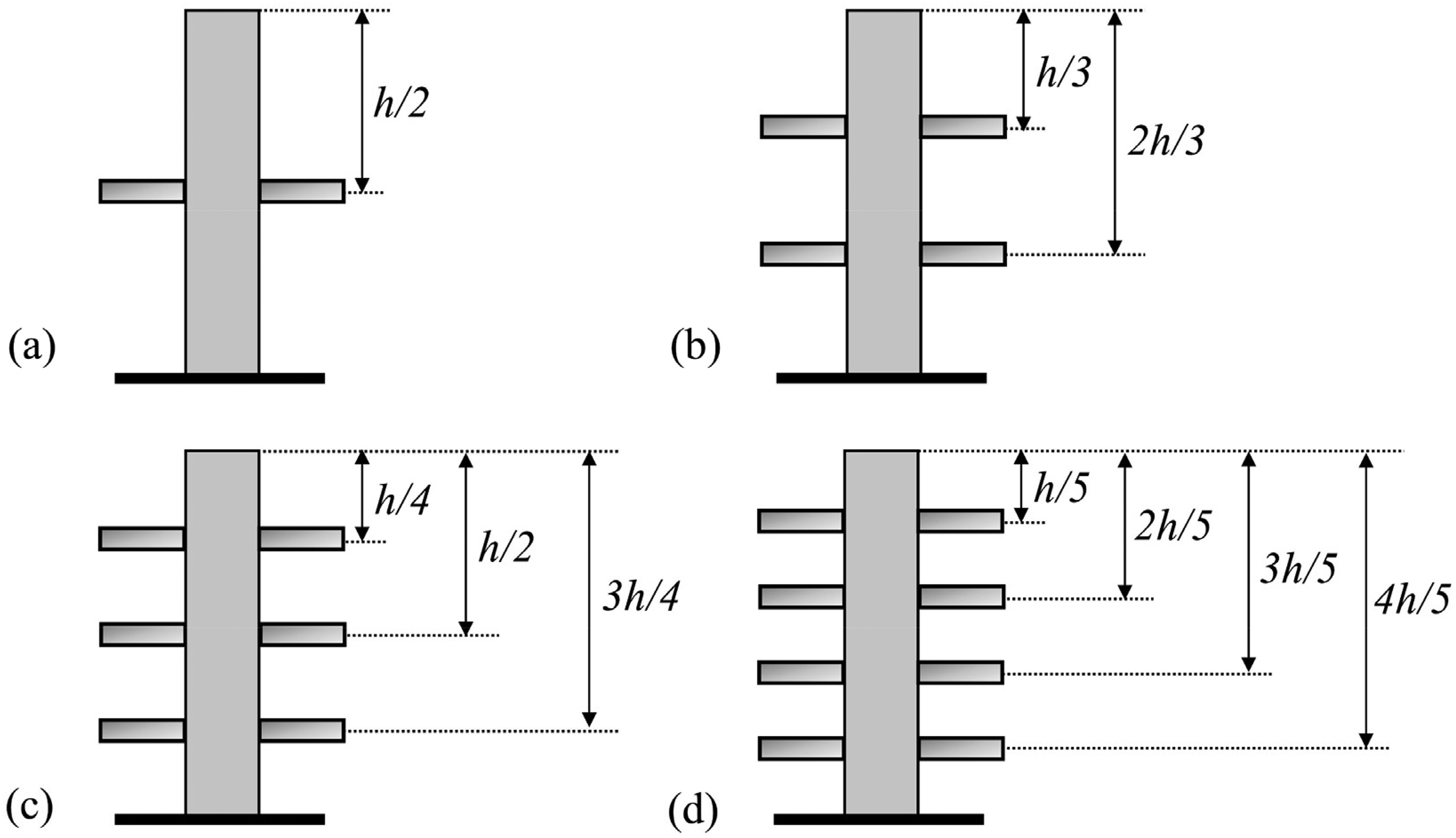
Optimum location of outrigger(s) according to Ref. 20
Employing outriggers can enhance the structural robustness in the event of a sudden loss of a local structural element or a connection.20,29 This is achieved by providing alternative load paths that can prevent progressive collapse and redistribute the forces upon any local failure. 20 In timber structures, and due to the brittle nature of wood under tension and shear, addressing this issue is of great importance.30,31
Several studies have been conducted on the use of outriggers in concrete, steel and composite structures, but little research has been done on timber structures. A study by Bollards
32
showed that timber structures up to 20 storeys are possible using outriggers together with a large central CLT core (
The aim of this article is to investigate the feasibility, advantages and limitations of using outriggers in multi-storey timber buildings. To achieve this, parametric analysis using finite element method (FEM) was performed in conjunction with the respective Eurocodes and standards. The optimum location of one and two outriggers was investigated considering lateral displacements and wind-induced accelerations as optimisation criteria. Several outrigger layouts were investigated, and their efficiency is compared. The effects of several parameters such as outrigger stiffness, number of storeys and wind velocity were also investigated.
Timber structures, due to their lightweight and moderate stiffness, are typically governed by the serviceability limit state (SLS).4–11 Therefore, this article focuses on the SLS. However, since the introduction of an outrigger may cause force concentration in structural members and connections at the outrigger level, ultimate limit state (ULS) should be considered as well. In this article, some ULS considerations are briefly discussed to validate the feasibility of such structural system in timber buildings.
Materials and methods
The structural system
Figure 3 shows a 3D view of an example multi-storey timber building. The lateral load resisting system (LLRS) in X direction consists of two continuous interior CLT walls, two continuous exterior glued laminated timber (glulam) columns, glulam beams with semi-rigid moment connections and an outrigger. The LLRS in Y direction consists of global diagonal bracings and CLT walls. This article focuses on the structural system in X direction (interior frame with
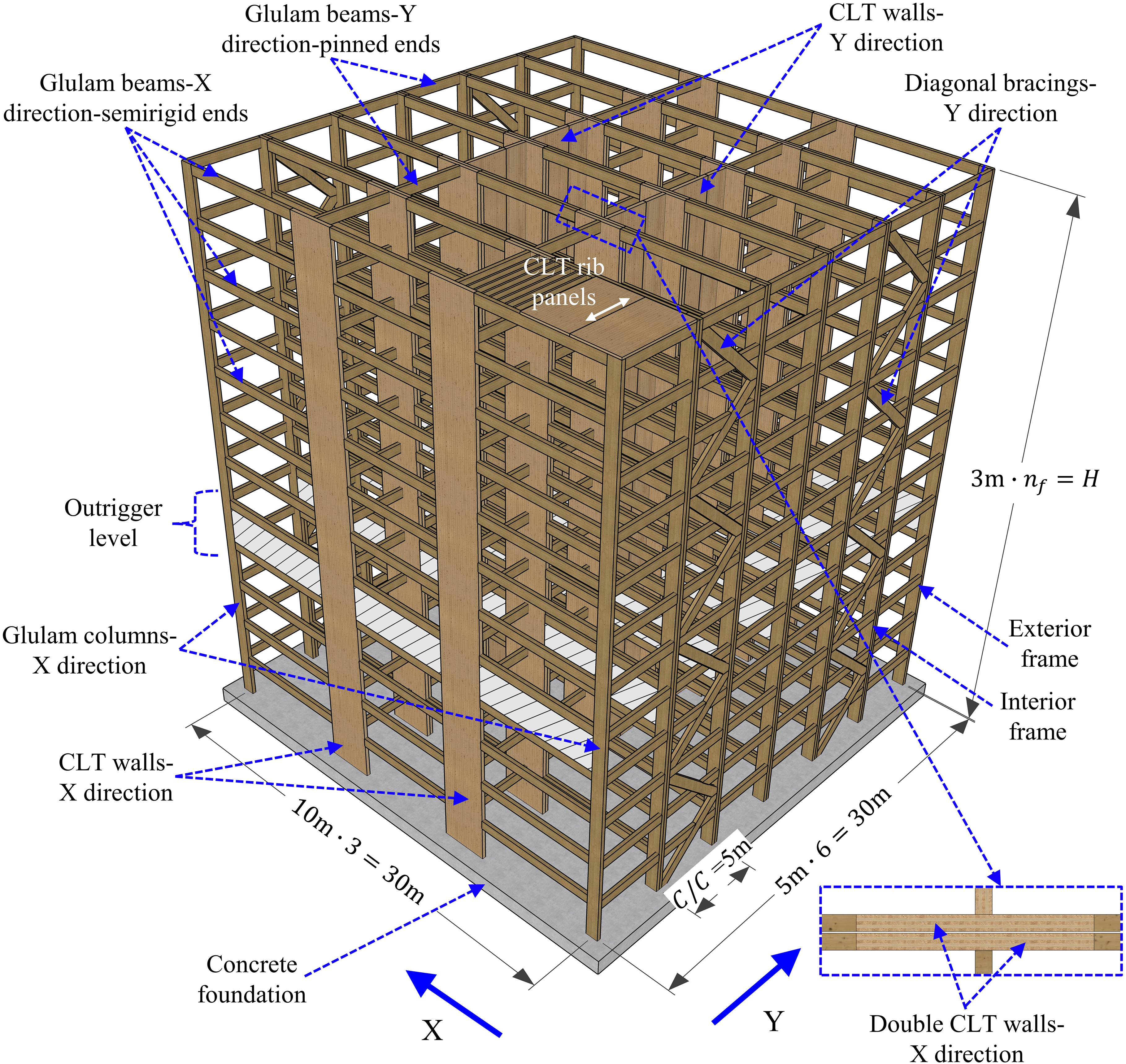
3D view of an example multi-storey timber building.
In this article, six variations of outrigger layouts were analysed (see Figure 4), and their performance is compared. The variations shown in Figure 4(a)–(e) combine MRTFs with outriggers. The first four variations (Figure 4(a)–(d)) employ a glulam truss as outrigger. One variation (Figure 4(e)) employs a CLT panel as outrigger. In the last variation, each of the interior CLT walls was replaced with diagonal truss bracing (consisting of two glulam columns and glulam global diagonal bracing); see Figure 4(f). The span length between each pair of glulam columns replacing an interior CLT wall is equal to the CLT wall width. In this variation (Figure 4(f)), all connections were assumed pinned. The purpose is to compare the variation shown in Figure 4(f) with the variations shown in Figure 4(a)–(e), which relies on moment connections. For all variations shown in Figure 4, the number of storeys was varied from 12 to 20 storeys. Hereafter, the different variations are referred to as variations (a)–(f).
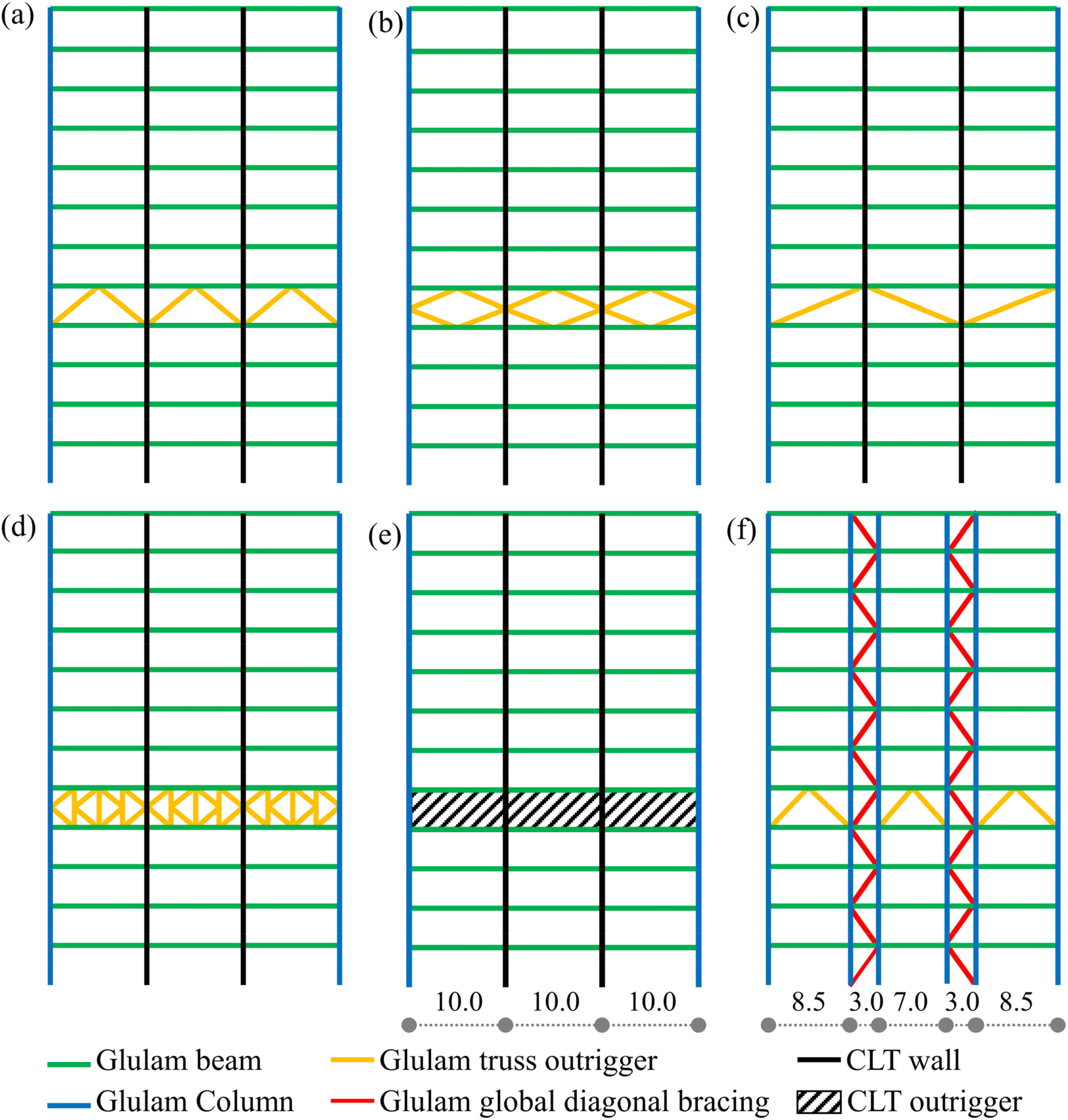
Variations of outrigger layouts (a) variation a, (b) variation b, (c) variation c, (d) variation d, (e) variation e and (f) variation f.
Material properties and cross-sections
Wood is an anisotropic material with different properties in different directions. 34 The material can be modelled as orthotropic with three orthogonal symmetry planes. 34 Further practical simplification is to model wood with equal properties across the grain. In this study, the glulam was assumed of strength class GL30c as defined by EN 14080. 35
In this study and to simplify the modelling using FEM, equivalent material properties of CLT were calculated using the method proposed by. 36 A uniform cross-section with a thickness equal to the actual thickness of the CLT and equivalent material properties was used, that is the cross-lamination is considered indirectly. It was assumed that (2/3) of the layers are along the longitudinal (main) direction and the remaining (1/3) are along the orthogonal direction, confer Figure 5(c). This simplified modelling approach is shown to properly capture the in-plane behaviour of CLT. 37 The lamellae constituting the CLT panels were assumed of strength class C24 as defined by EN 338. 38
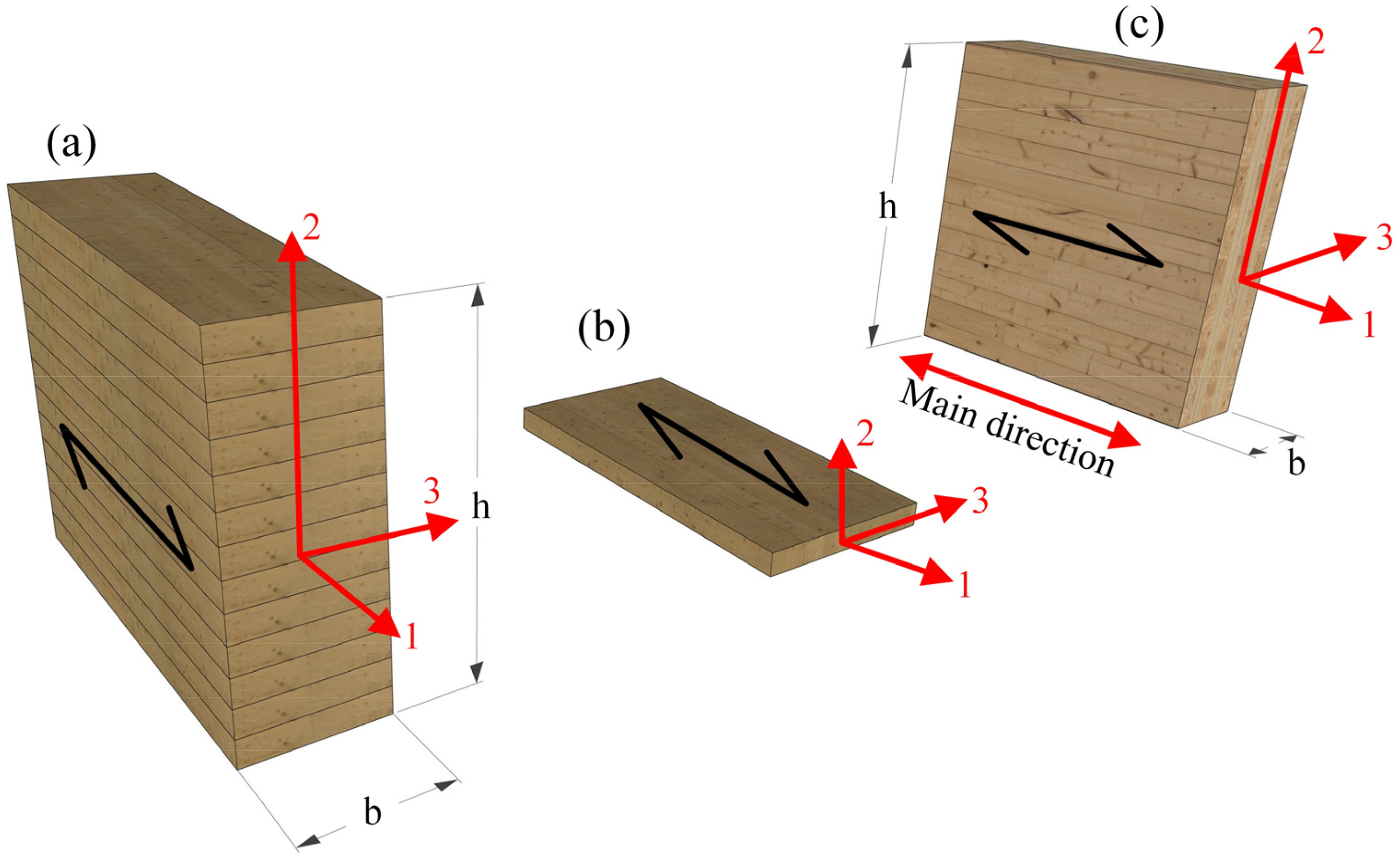
Material axes and cross-sections (a) glulam, (b) C24 lamellae and (c) CLT element.
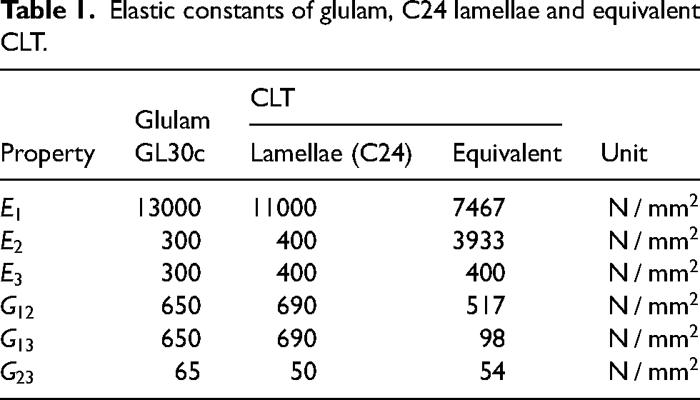
The elastic constants of the glulam, the C24 lamellae, and the equivalent CLT are summarised in Table 1. The corresponding material axes are shown in Figure 5.
Elastic constants of glulam, C24 lamellae and equivalent CLT.
Walls, columns, beams, outriggers and global diagonal bracing were assumed of double cross-section, see Figure 3. Dimensions of walls, columns, beams, were reasonably assumed and summarised in Table 2. Dimensions of outriggers were varied, and the global diagonal bracing were modelled in terms of their axial stiffness as will be explained in section ‘Finite element method and analytical model’.
Cross-sections of walls, columns, beams, outriggers and global bracing.
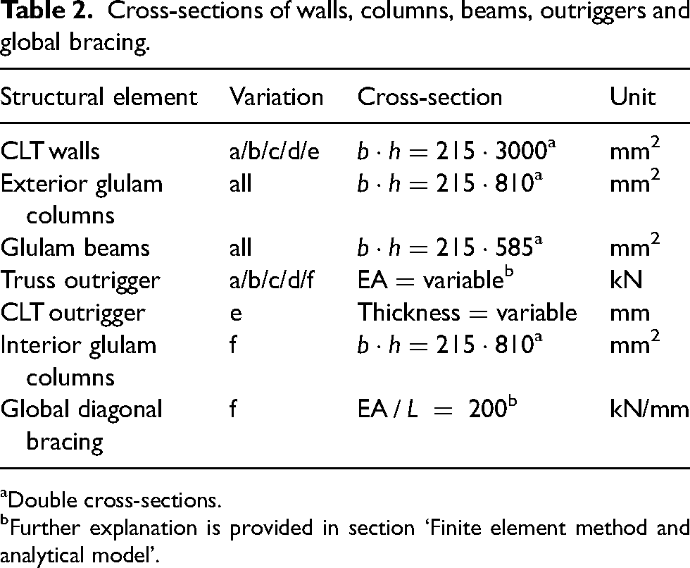
Double cross-sections.
Further explanation is provided in section ‘Finite element method and analytical model’.
Finite element method and analytical model
CSI SAP2000 39 was used to perform 2D linear elastic FEM. The open application programming interface was used to drive the software externally. Figure 6 shows the analytical model of variation (b), with example connections details based on Refs.6,16,40,41 Glulam columns and beams were modelled using linear elements (considering both bending and shear deformations) with material properties and cross-sections in Tables 1 and 2. The CLT walls were modelled using linear elements with equivalent properties and cross-sections in Tables 1 and 2. The linear elements representing the CLT walls were verified against the layered shell elements available in CSI SAP2000 39 under in-plane loading. The verification was done on both stresses and deformations and the difference was less than 5%. Hence, linear elements were deemed to have sufficient accuracy for the purpose of this study.
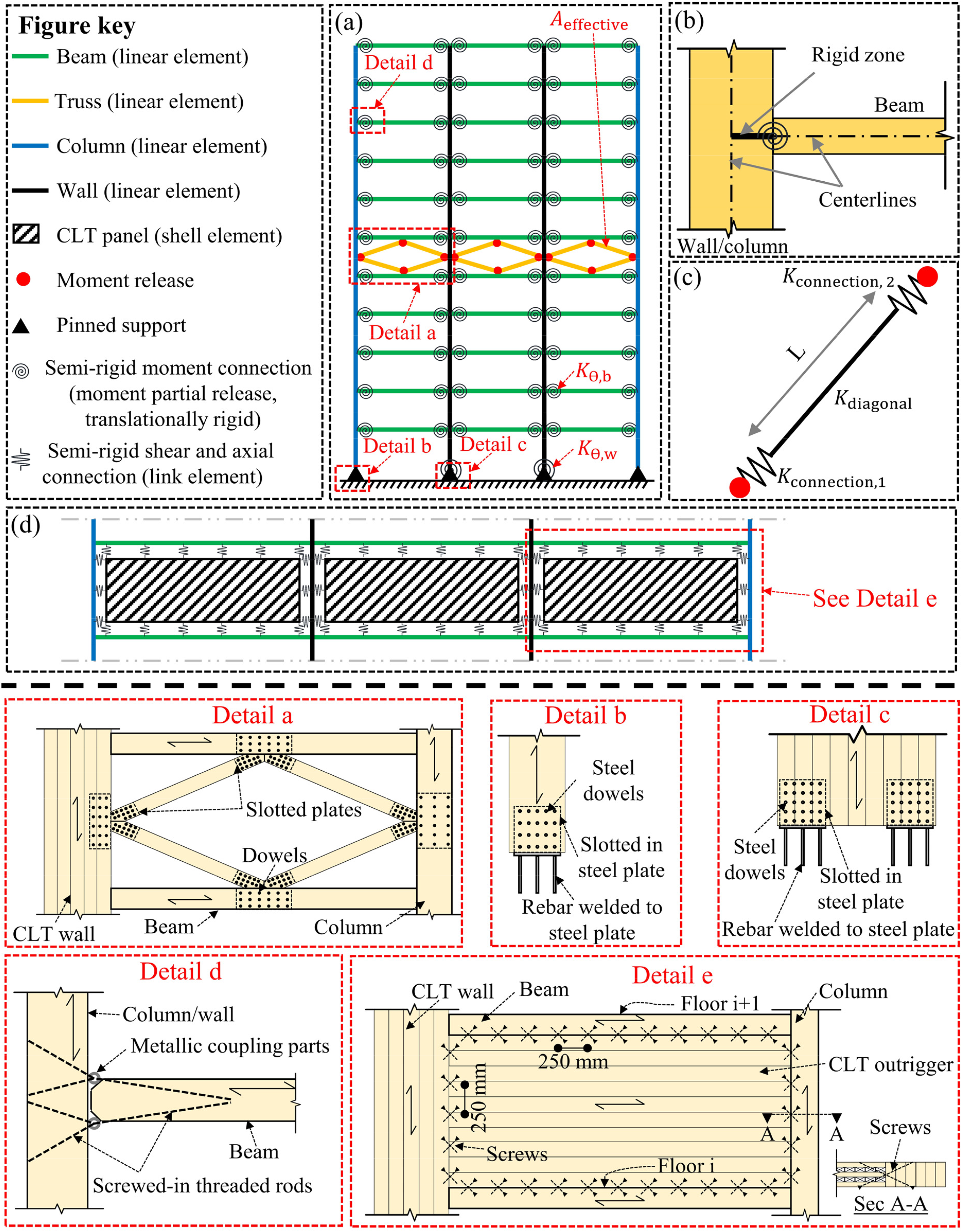
Analytical model with example connections details, (a) 2D frame with truss outrigger, (b) rigid zone in beam-to-wall/column connections, (c) diagonal/truss element and (d) CLT outrigger.
The CLT panels used as an outrigger in variation (e) were modelled using shell elements with the equivalent properties in Table 1. The shell elements are connected to the main structural system using link elements as shown in Figure 6(d). The link elements represent the connections (e.g. self-taping screws) between the CLT outrigger and the main structural system. The link elements have only axial and shear stiffness (no rotational stiffness).
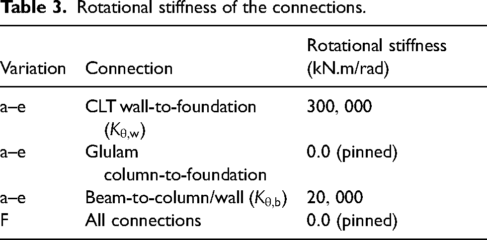
The beam-to-wall/column connections were assumed semi-rigid with finite rotational stiffness. The stiffness was reasonably assumed based on the experimental work done by Vilguts et al. 42 and the analytical method proposed by Stamatopoulos et al. 43 The stiffness values of the connections are summarised in Table 3.
Rotational stiffness of the connections.
CLT walls and glulam columns have finite cross-sectional dimensions. Modelling them as linear elements connected at nodes results in larger beam spans, leading to a softer structural system. To account for the fact that the clear spans of beams are shorter than the centreline-to-centreline spans, the end length offset option available in CSI SAP2000 39 was used. The concept of the end length offset is illustrated in Figure 6(b). At the beam ends, a length equal to half the wall/column width is assumed rigid for bending and shear deformations.
The truss outrigger and the global diagonal bracing elements (confer Figure 4) were modelled using linear elements with pinned ends. The presence of connections at the ends implies the need to use two link elements representing the connections, see Figure 6(c). This situation resembles three springs in series, which can be replaced by one spring with an effective stiffness: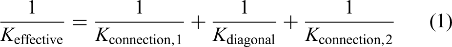
The diagonal can then be modelled using only one linear element with axial stiffness 
Loads and limit states
In this study, three different types of loads were considered, namely: dead load
Gravity loads.
Including the weight of floors and finishings, excluding the own weight of beams, columns, walls and diagonals.
According to EN 1991-1-1. 45
For the calculation of lateral displacements due to wind, the characteristic load combination as defined in EN 1990
46
with wind as a leading variable was used:
EN 1995-1-1
47
recommends a deflection limit of 
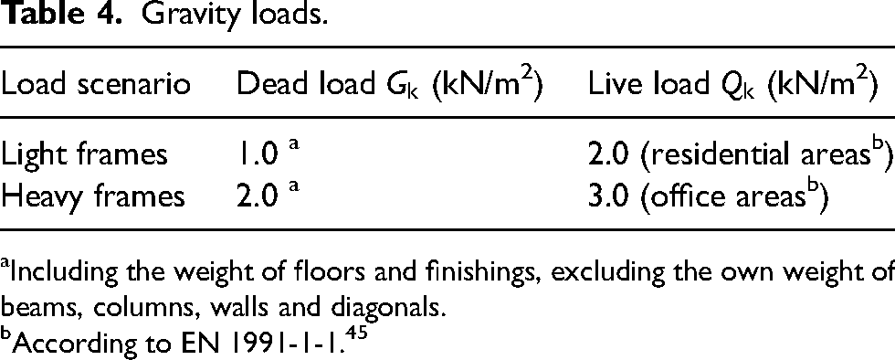
EN 1991-1-4 44 provides two equivalent procedures to estimate the wind-induced acceleration. Both procedures are based on gust factor approach but use different simplifications. 48 In this article, the wind-induced acceleration was calculated using procedure 1 available in Annex B of EN 1991-1-4. 44
For the calculation of acceleration according to EN 1991-1-4,
44
the mode shape and the fundamental frequency are required. To obtain the mode shape and the fundamental frequency, modal analysis was performed using CSI SAP2000.
39
In modal analysis, the mass corresponding to quasi-permanent load combination defined in EN 1990
46
was used:
The parameters used in the calculation of wind-induced acceleration.
Human perception of acceleration is subjective, and therefore there exist several comfort criteria that can be used to assess the performance of a building under wind load. 50 In this article, the criterion provided by ISO10137 51 was used. ISO10137 51 covers the range from a fundamental frequency of 0.063 to 5 Hz for a maximum wind velocity with a return period of one year. The criterion is depicted in Figure 7.
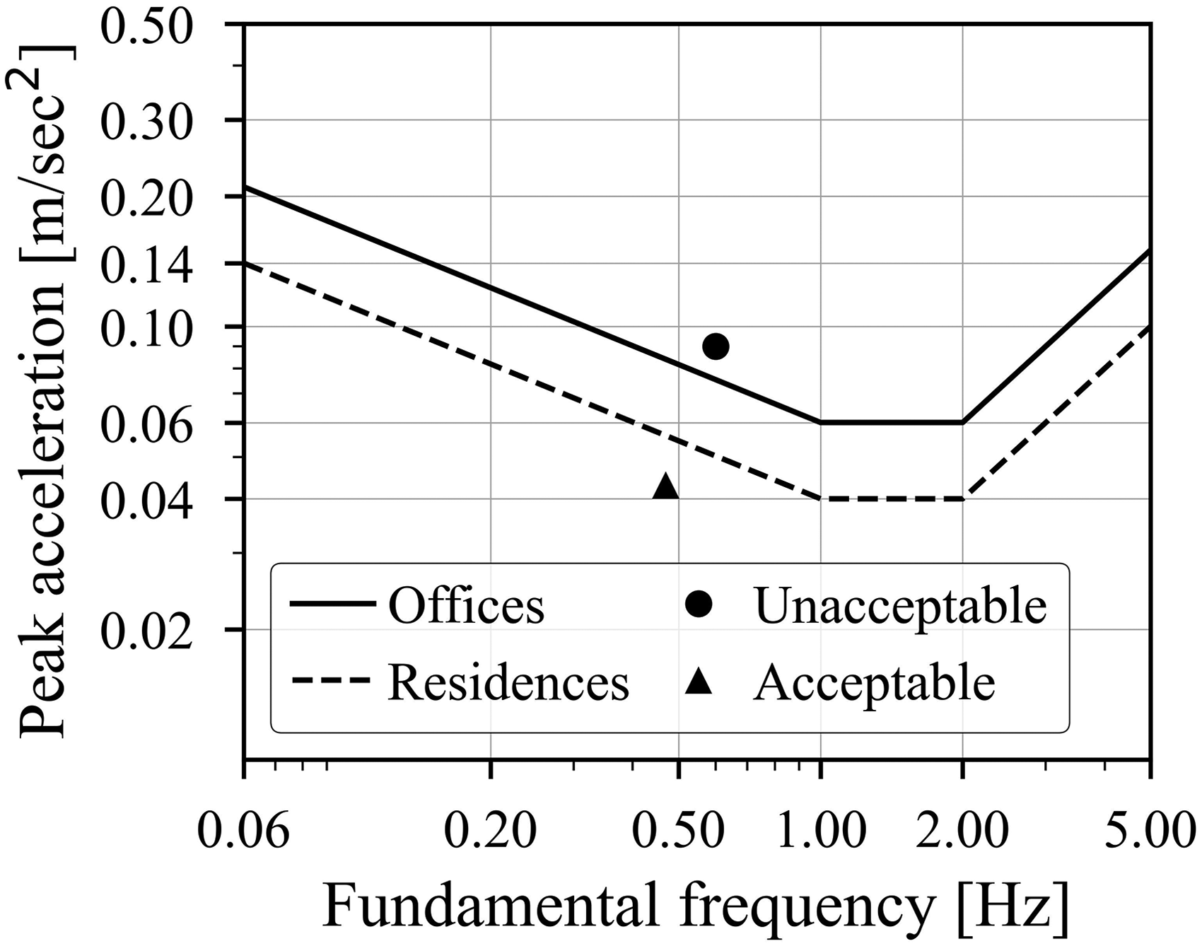
Evaluation curves for wind-induced accelerations according to ISO10137. 51
For the calculation of forces and stresses used for discussing the ULS, the fundamental ULS combination defined in EN 1990
46
with either wind or live load as leading variable action:

The forces and stresses were calculated using the envelop of equations (6) and (7).
Results and discussion
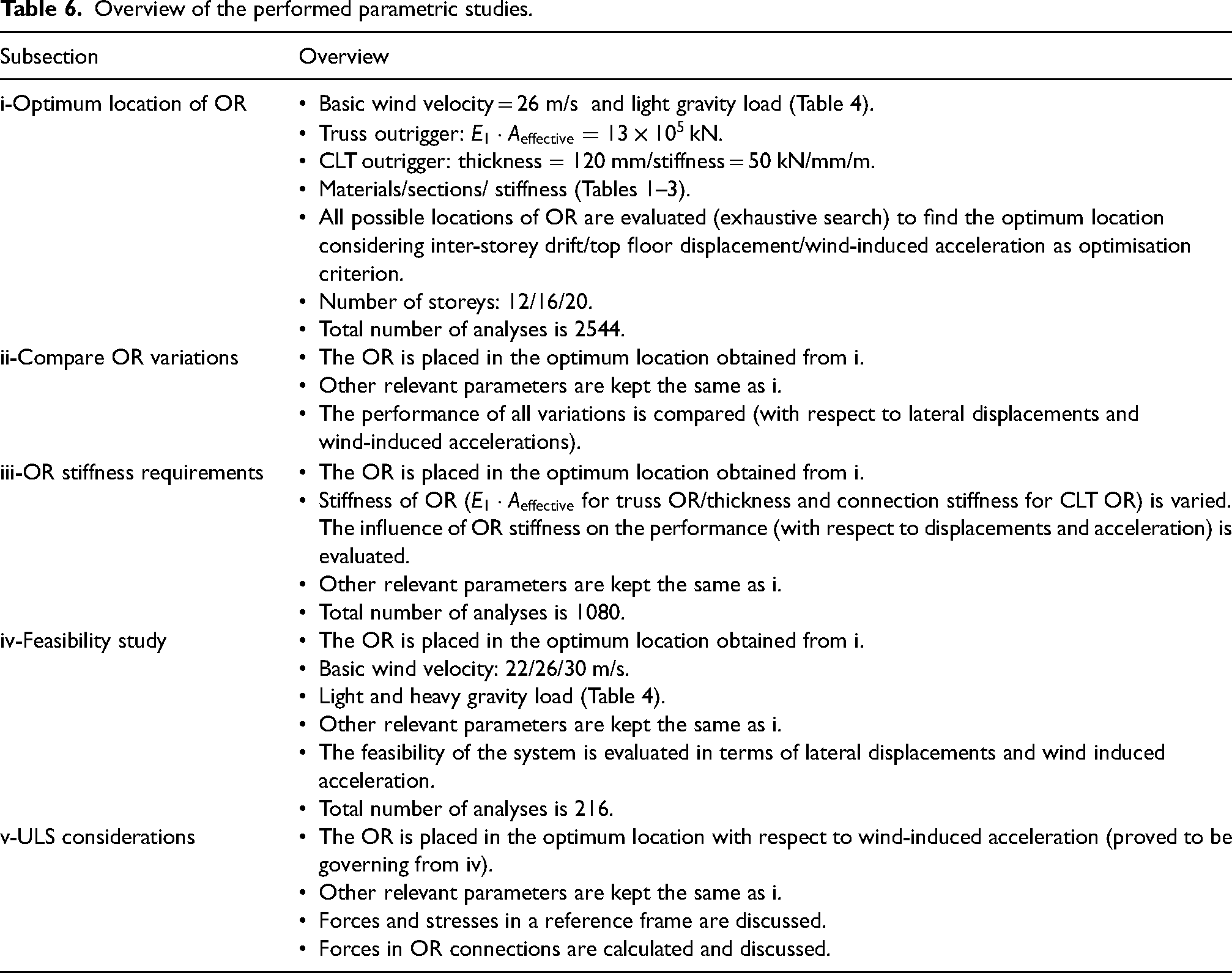
In this section, five subsections are outlined to address the optimum location of outriggers, compare the efficiency of the different variations shown in Figure 4, estimate the stiffness requirements of outriggers, show the feasibility of the system with respect to SLS, and highlight some ULS considerations. For this purpose, five parametric studies were performed. Table 6 provides an overview of the performed parametric studies.
Overview of the performed parametric studies.
Optimum location of outrigger(s)
To identify the optimum location(s) of OR, three optimisation criteria were considered, namely: top floor displacement, inter-story drift (IDR) and wind-induced acceleration in the top storey. A basic wind velocity of 26 m/s with light gravity loads (see Table 4) was assumed. Three number of storeys were considered, namely: 12, 16 and 20. Exhaustive search algorithm was used to find the optimum location.
The optimum location for one and two outriggers is shown in Figure 8(a) for variations (a)–(e) and in Figure 8(b) for variation (f). The optimal location was identical for variations (a)–(e). The location is expressed as a fraction of the total height H. It is worth mentioning that the optimum location for the cases of 12, 16 and 20 storeys differs slightly, approximately 5% of H. Therefore, an average value for the three cases was considered.
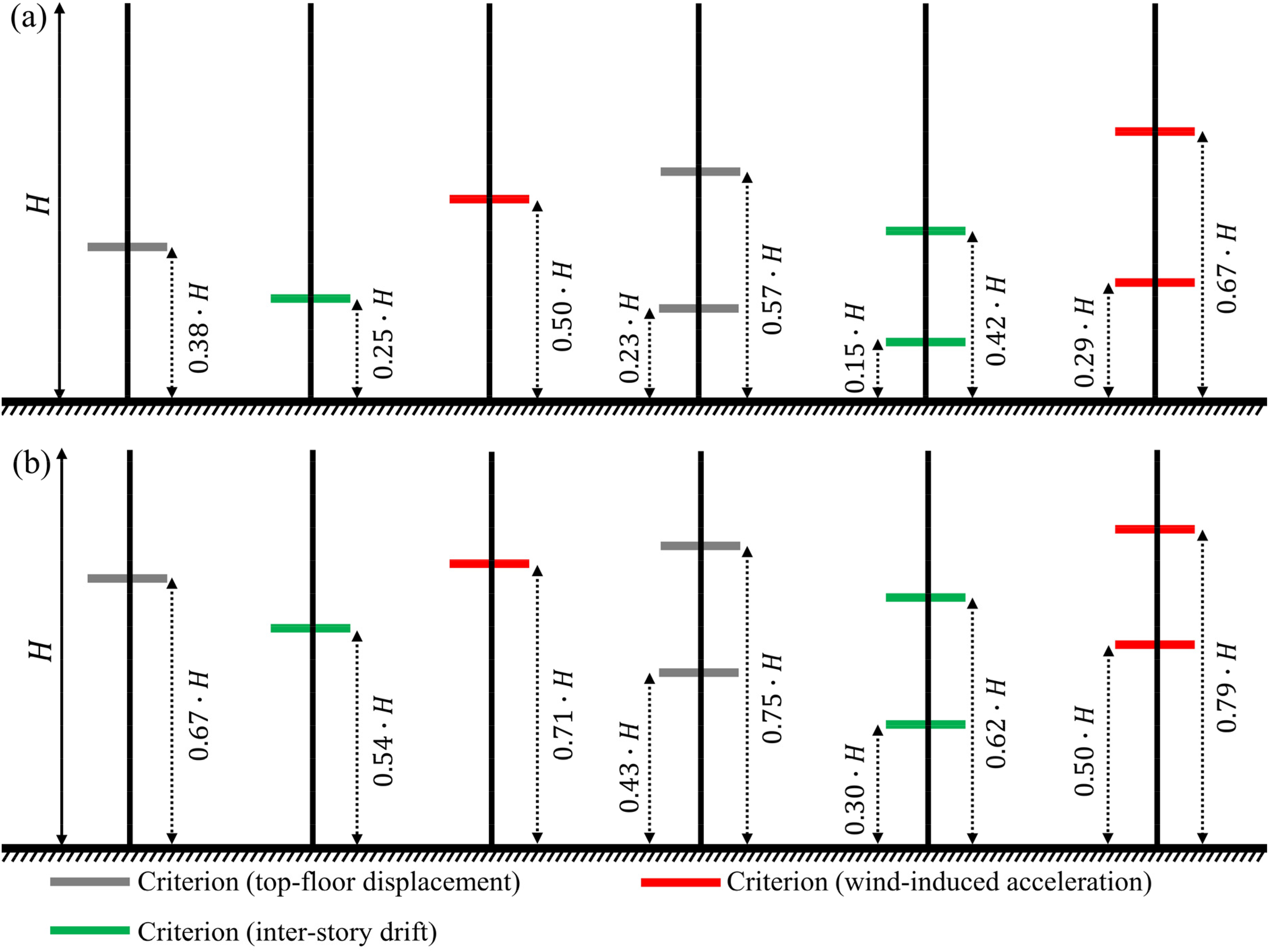
Optimum location of OR based on three criteria for (a) variation a–e; and (b) variation f.
Comparing Figure 8(a) and (b), the location of OR(s) is lower (closer to the base) for variations (a)–(e) than variation (f). Assuming no OR is used, the mode shapes for variations (a)–(e) (identical for no OR case) and for variation (f) are plotted in Figure 9. Comparing the mode shapes for variations (a)–(e) and for variation (f), it is obvious that variation (f) exhibits more flexural dominant mode shape than variations (a)–(e). Hence the ORs are closer to the top for variation (f). It is also noticeable that the optimum location for wind-induced acceleration is the highest, followed by top floor displacements and inter-storey drift.
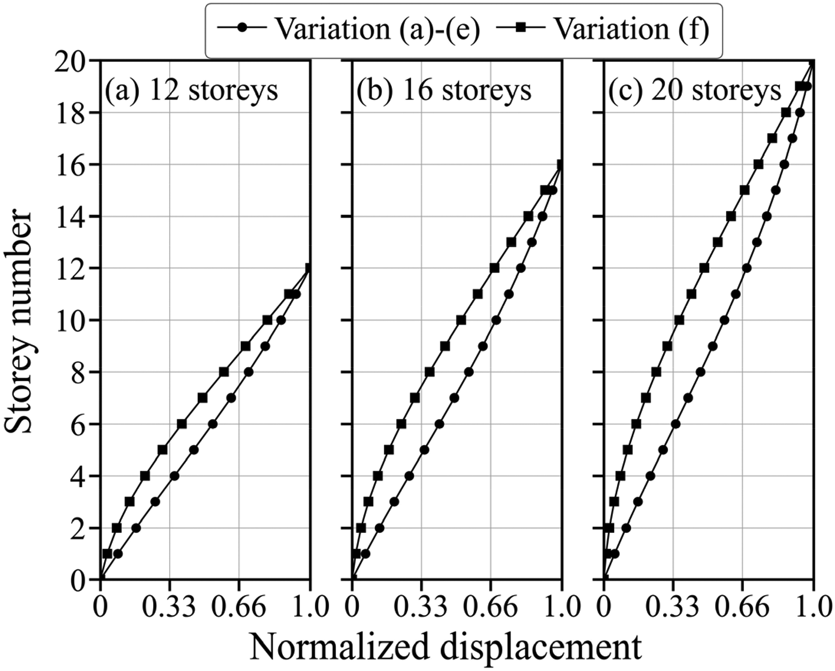
Mode shapes with no outriggers.
It was observed that when the outriggers are placed at the optimum location for IDR, a reduction of over 94% in top floor displacement is attained. Therefore, it is reasonable to assumed that the optimum location for lateral displacements (considering both IDR and top displacement simultaneously) is the same as for IDR.
Comparison of outrigger variations
To compare the efficiency of the variations shown in Figure 4, the ratios of top floor displacement (
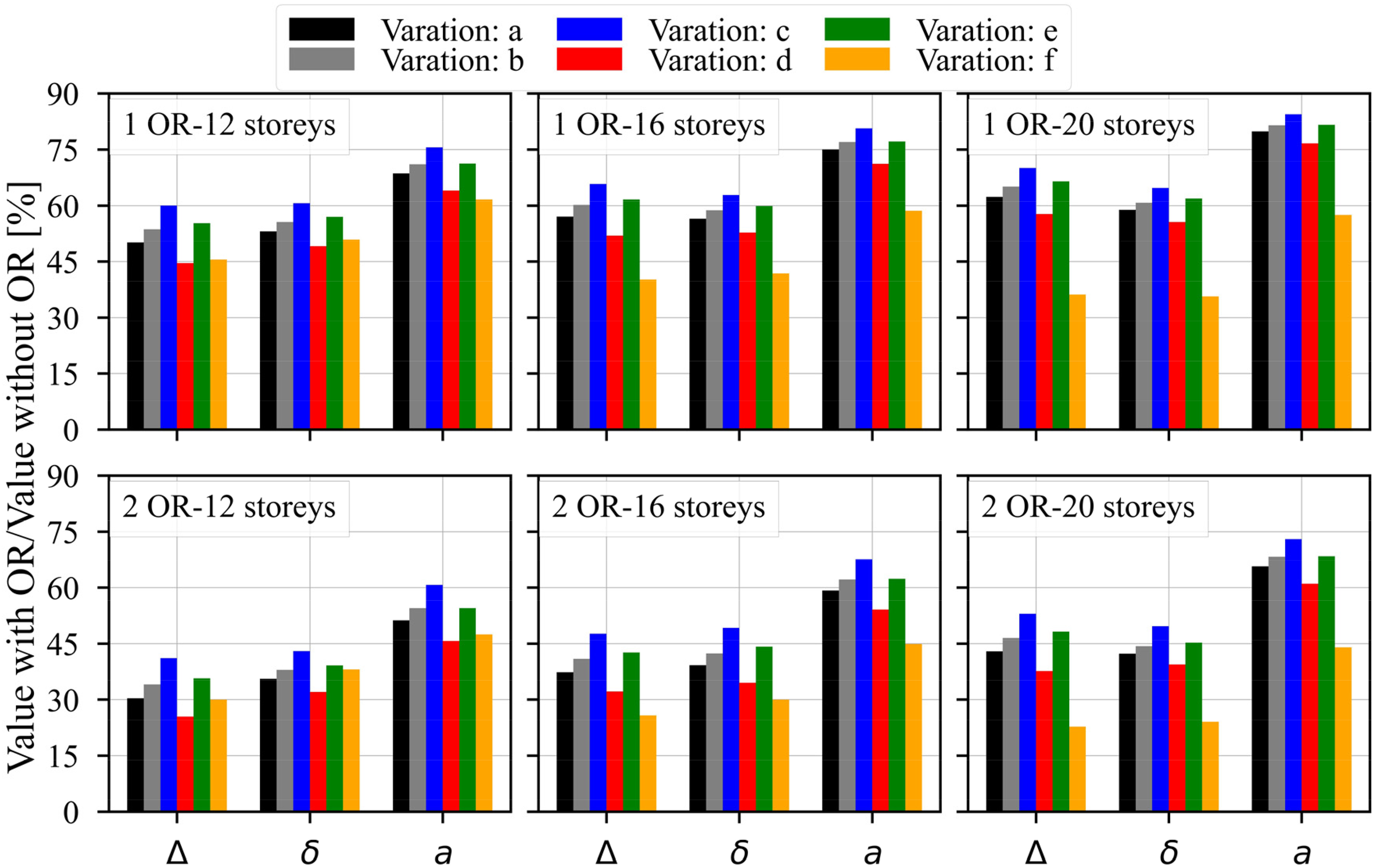
Ratios of top floor displacement (Δ), inter-storey drift (δ) and wind-induced acceleration (a) with the use of OR to the case without OR.
As shown in Figure 10, variation (f) shows the highest efficiency for the case of 16 and 20 storeys. This is expected as the outrigger system is generally less effective when the mode shape is more shear dominant. 29 The most effective variation among (a)–(e) variations is variation (d) followed by variation (a). Figure 10 also shows that ORs are less effective in reducing wind-induced acceleration compared to lateral displacements.
The presence of ORs stiffens the structure and leads to an increased fundamental frequency. The ratio of the frequency with ORs (
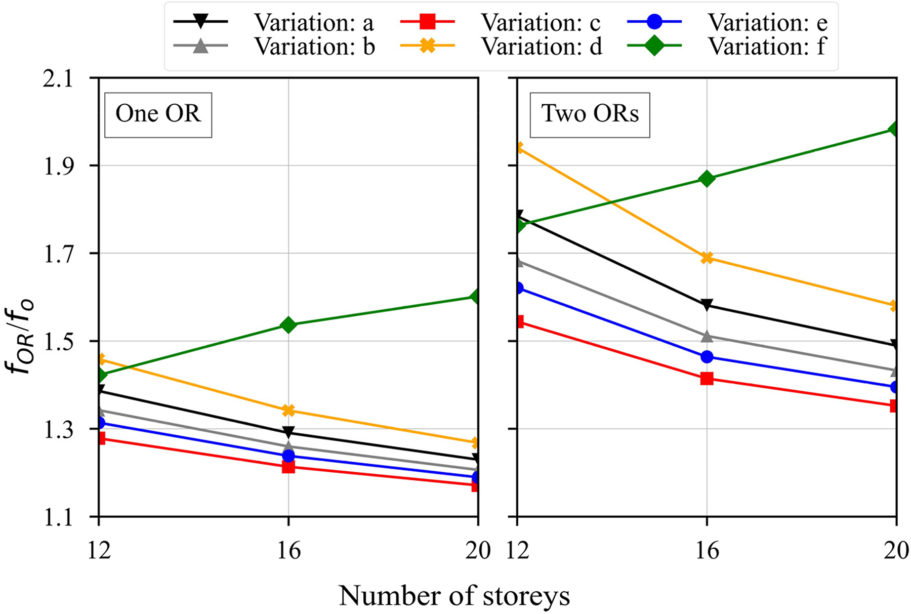
Ratio of the frequency with the use of OR
The constructability of each variation is also an important aspect to be compared. For some variations, namely: (a), (c) and (f), the OR connections and the moment connections (beam-wall/column) intersect. This intersection can impose constructability difficulties. In this regard, variations (b), (d) and (e) can provide more practical alternatives. However, variation (d) has more connections than variations (b) and (e), which might be undesired.
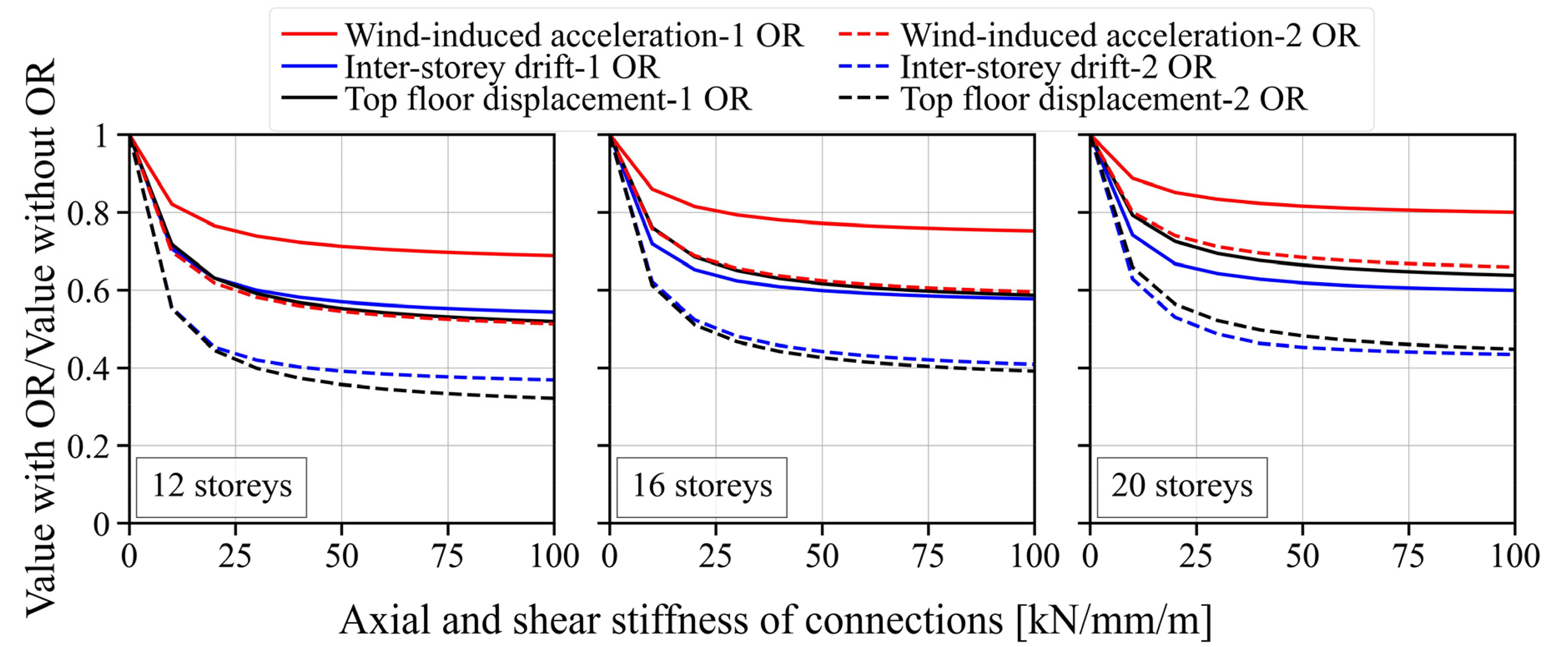
Stiffness of outriggers
Since the lengths of the truss elements are not the same for all variations shown in Figure 4, it is best to replace the effective axial stiffness (
Figure 12 shows the lateral displacements (
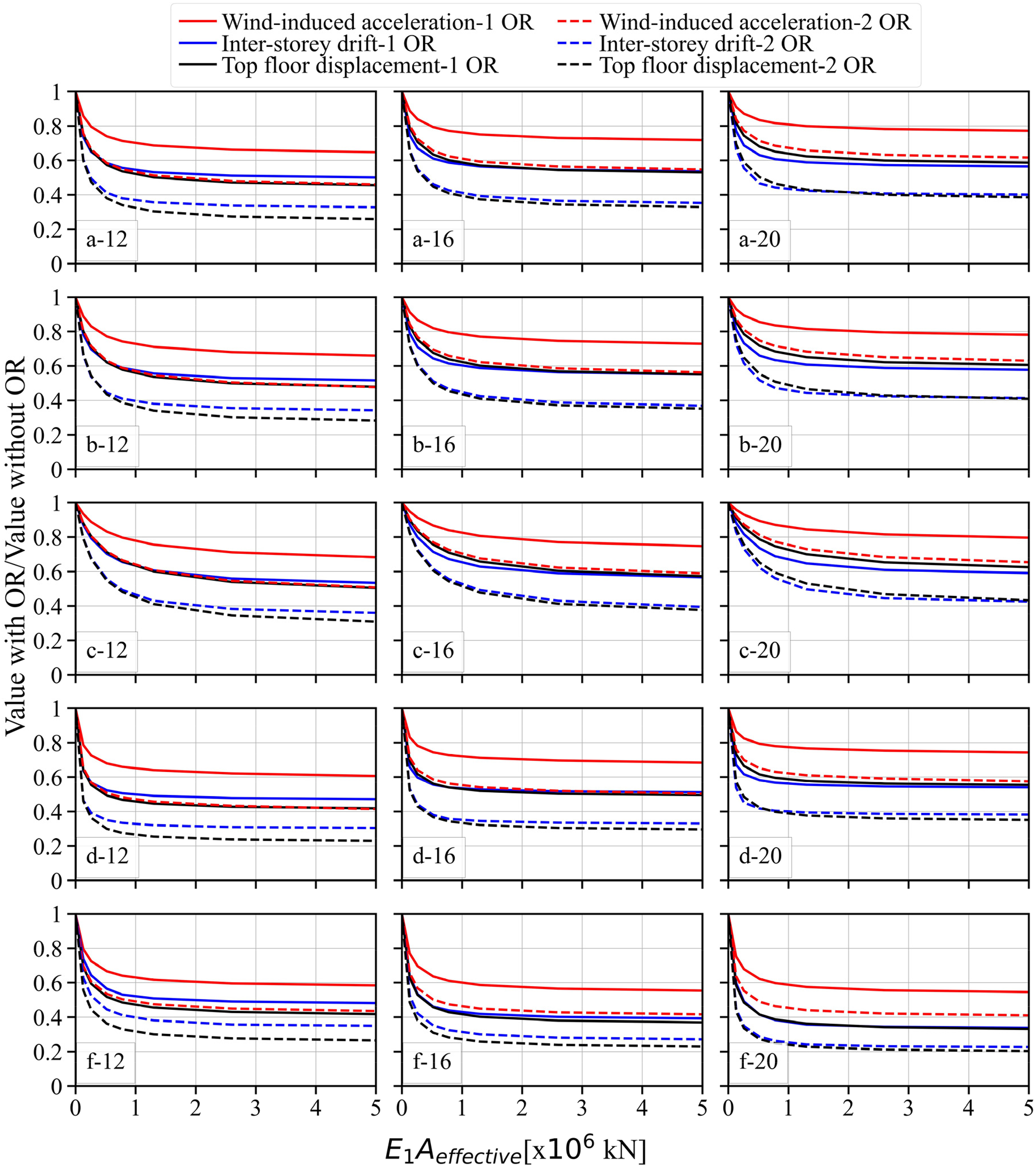
Lateral displacements and acceleration ratios as function of
For variation (e), the outrigger stiffness was measured in terms of the thickness of the CLT panels used as OR, and the stiffness of the connections connecting the CLT OR to the main structure. It was assumed that these connections have shear and axial stiffness of the same magnitude. Figures 13 and 14 show the lateral displacements and wind induced acceleration as function of CLT thickness and the connections stiffness, respectively. When the CLT thickness was varied, the connections stiffness was set to 100 kN/mm/m. When the connections stiffness was varied, the CLT thickness was set to 300 mm. As shown in Figures 13 and 14, good reductions can be achieved with CLT thickness of around 100 mm and connections stiffness in the range of 25 to 50 kN/mm/m.
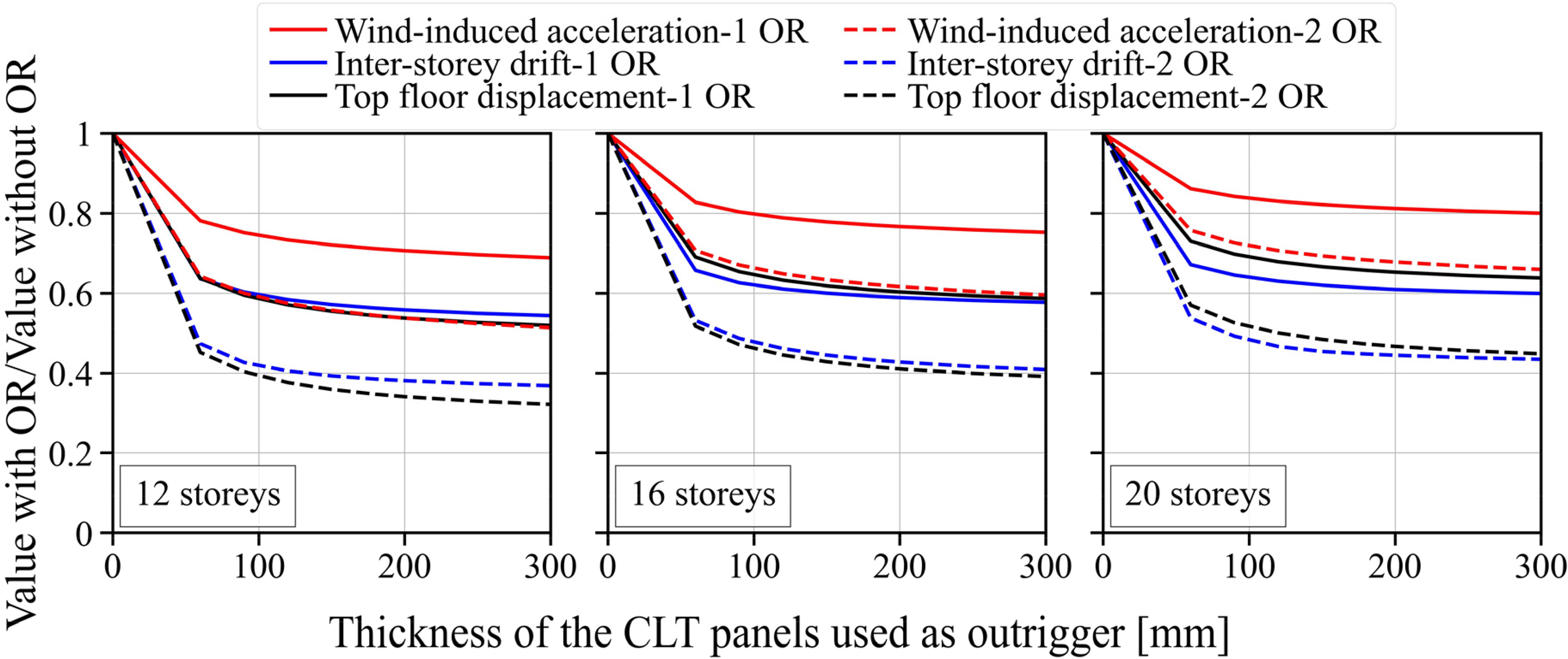
Lateral displacements and acceleration ratios as function of CLT OR thickness for variation (e).
Lateral displacements and acceleration ratios as function of axial and shear stiffness of the connections used in the CLT OR for variation (e).
Feasibility study
In this section, a parametric study is presented. The parameters used in this study are summarised in Table 7. The feasibility is evaluated in terms of top floor displacement, inter-storey drift and wind induced acceleration.
Parameters used in the feasibility study.
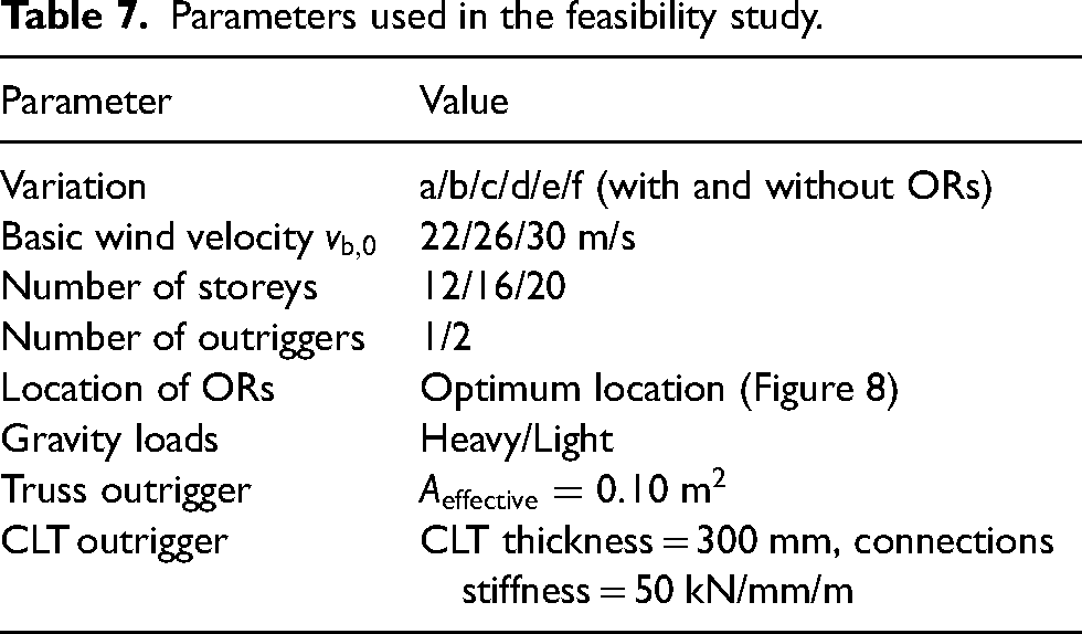
Figure 15 shows the peak acceleration for the frames in Table 7. For simplicity, variations (a)–(e) were considered one group, and variation (f) was considered the second group. For the frames shown in Table 7, Figures 16 and 17 show lateral displacements and inter-storey drift, respectively. Since linear elastic FEM was performed, gravity loads do not contribute to lateral displacements. Hence, Figures 16 and 17 are shown for the case of light frames.
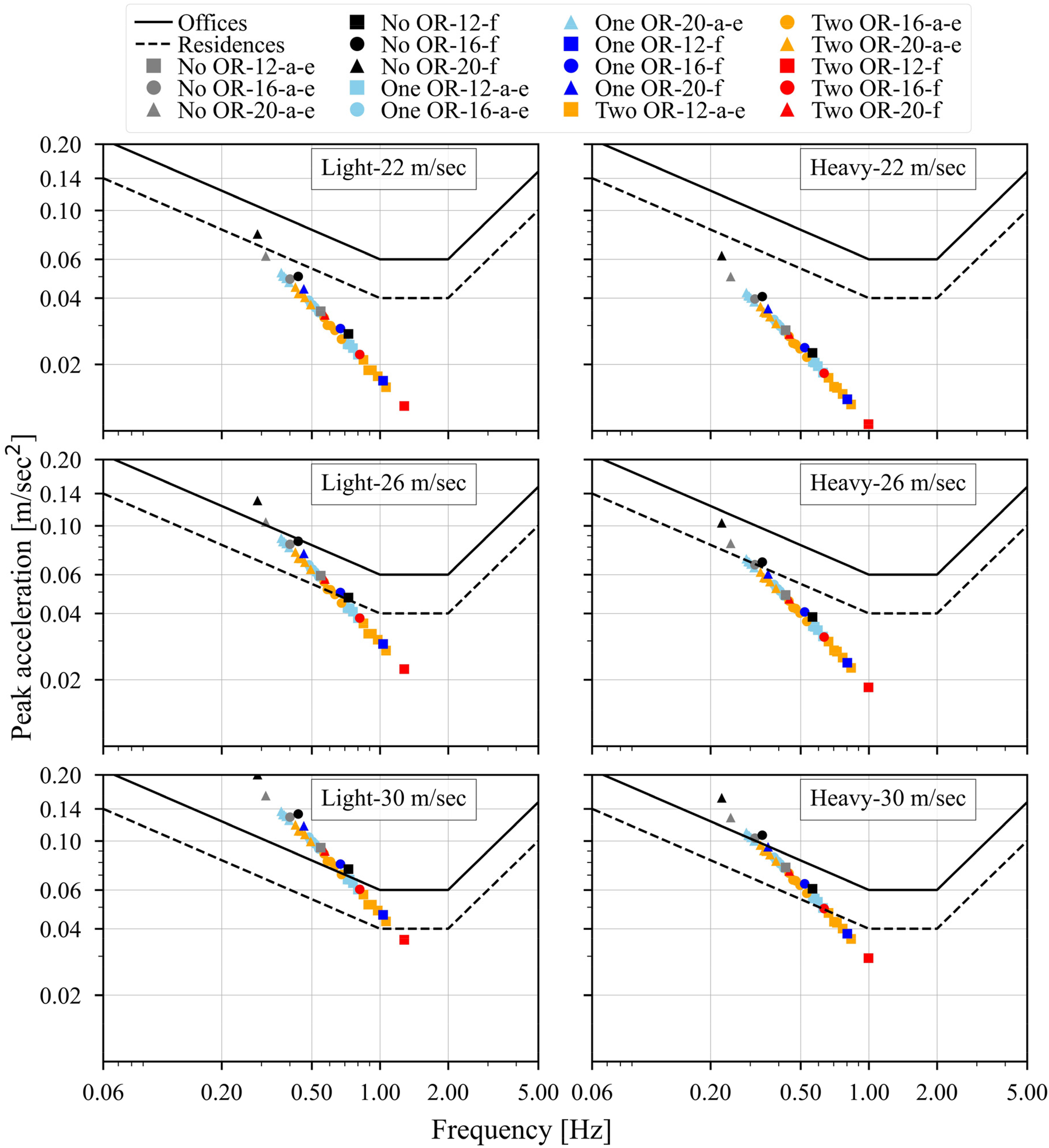
Wind-induced acceleration.
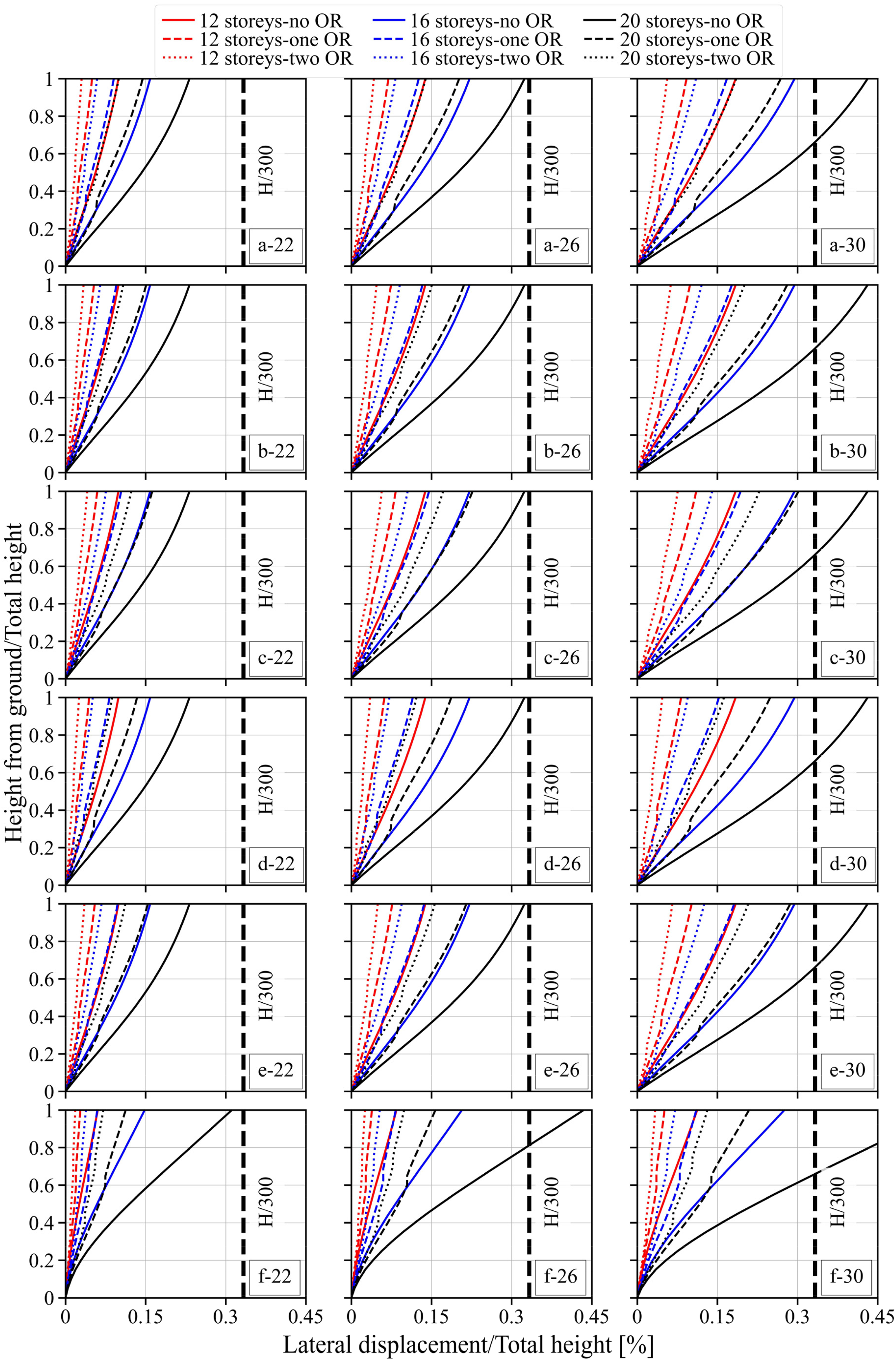
Lateral displacement for all variations (legend: variation-basic wind velocity).
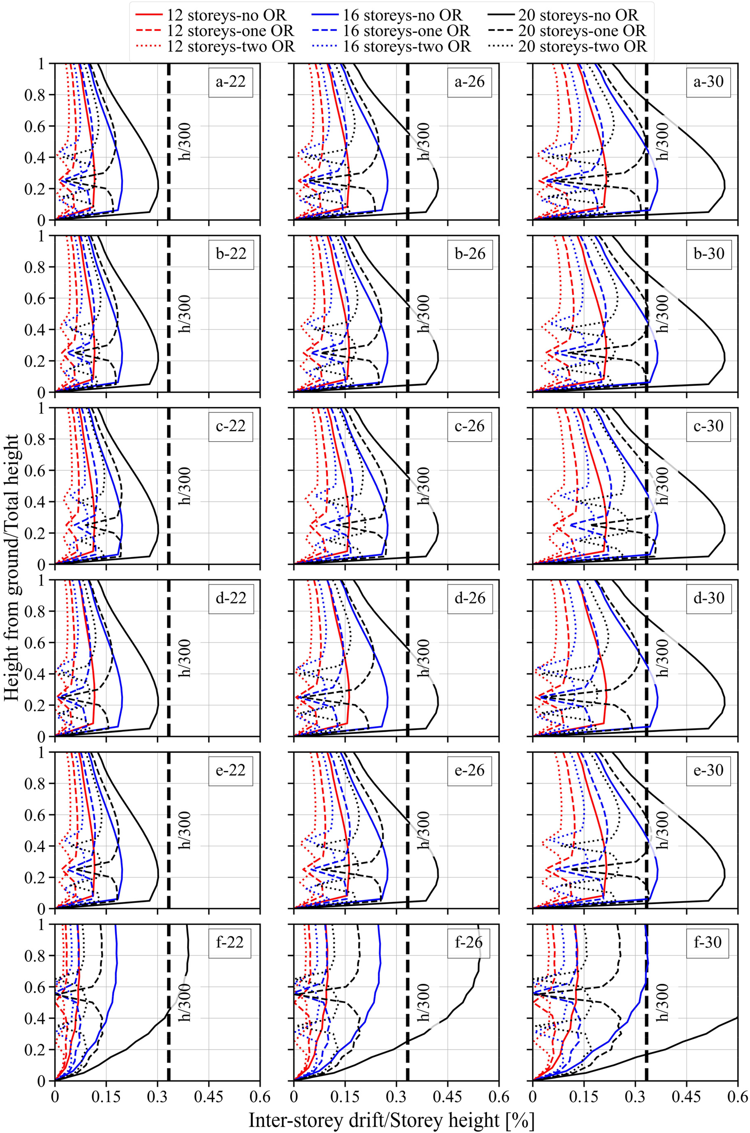
Inter-storey drift for all variations (legend: variation-basic wind velocity).
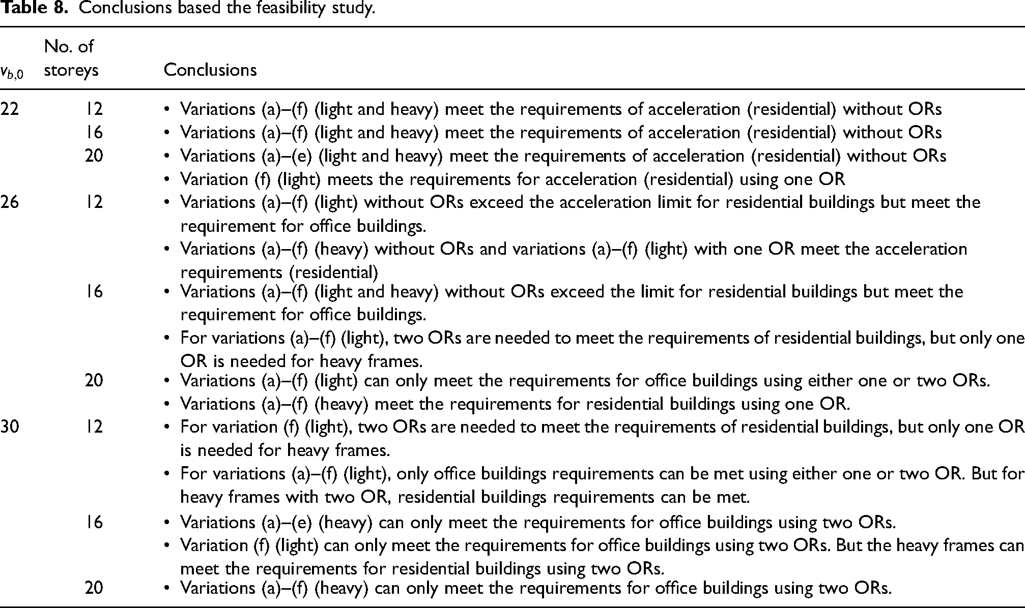
As shown in Figures 16 and 17, using only one OR, variations (a), (d) and (f) meet the requirements for top floor displacement and inter-storey drift for all basic wind velocities and all number of storeys. Based on Figures 15–17, it can be observed that wind-induced acceleration is the governing response parameter compared to lateral displacements. Based on Figures 15–17, several conclusions can be drawn, these are summarised in Table 8.
Conclusions based the feasibility study.
Ultimate limit state considerations
Some considerations with respect to the feasibility of the OR-system in terms of the ULS are provided in this section. In subsection ‘Stresses in an example frame’, the stress levels of the beams, columns and walls of a benchmark frame are used as a basis for discussion. In subsection ‘Forces in the OR truss members’, the force levels in the truss elements are summarised and discussed. In both subsections, the results come from the ULS design load combination given by equations (6) and (7).
Stresses in an example frame
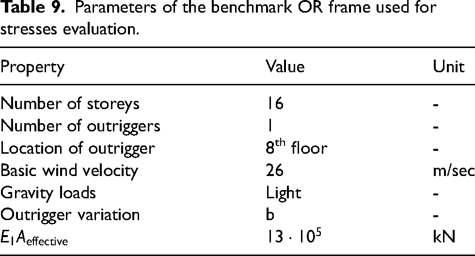
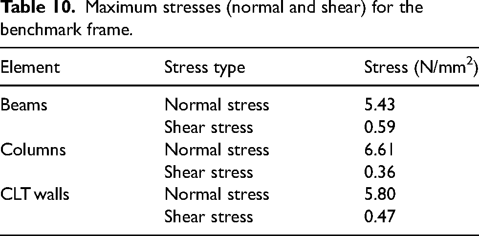
An OR frame with the properties shown in Table 9 is used as benchmark to investigate the stress levels in the beams, columns and walls. Other parameters such as number of bays, bay length, floor height, material properties, connections stiffness and cross-sections were kept the same as in section ‘Materials and methods’ of this article. The OR is placed at the optimal location based on wind-induced acceleration criterion. Stresses in beams, columns and walls are summarised in Table 10. Stresses in the truss elements of the OR are not reported here; the ULS of the truss elements are examined in greater detail in subsection ‘Forces in the OR truss members’. As shown in Table 10, the stress-levels are not very high, and these structural elements can be designed such that they satisfy the safety requirements.
Parameters of the benchmark OR frame used for stresses evaluation.
Maximum stresses (normal and shear) for the benchmark frame.
Forces in the OR truss members
The maximum forces (tension and compression) in the truss elements of the ORs were calculated for all variations except variation (e). The ORs were placed at the optimal location with respect to wind-induced acceleration. A basic wind velocity of 26 m/s and
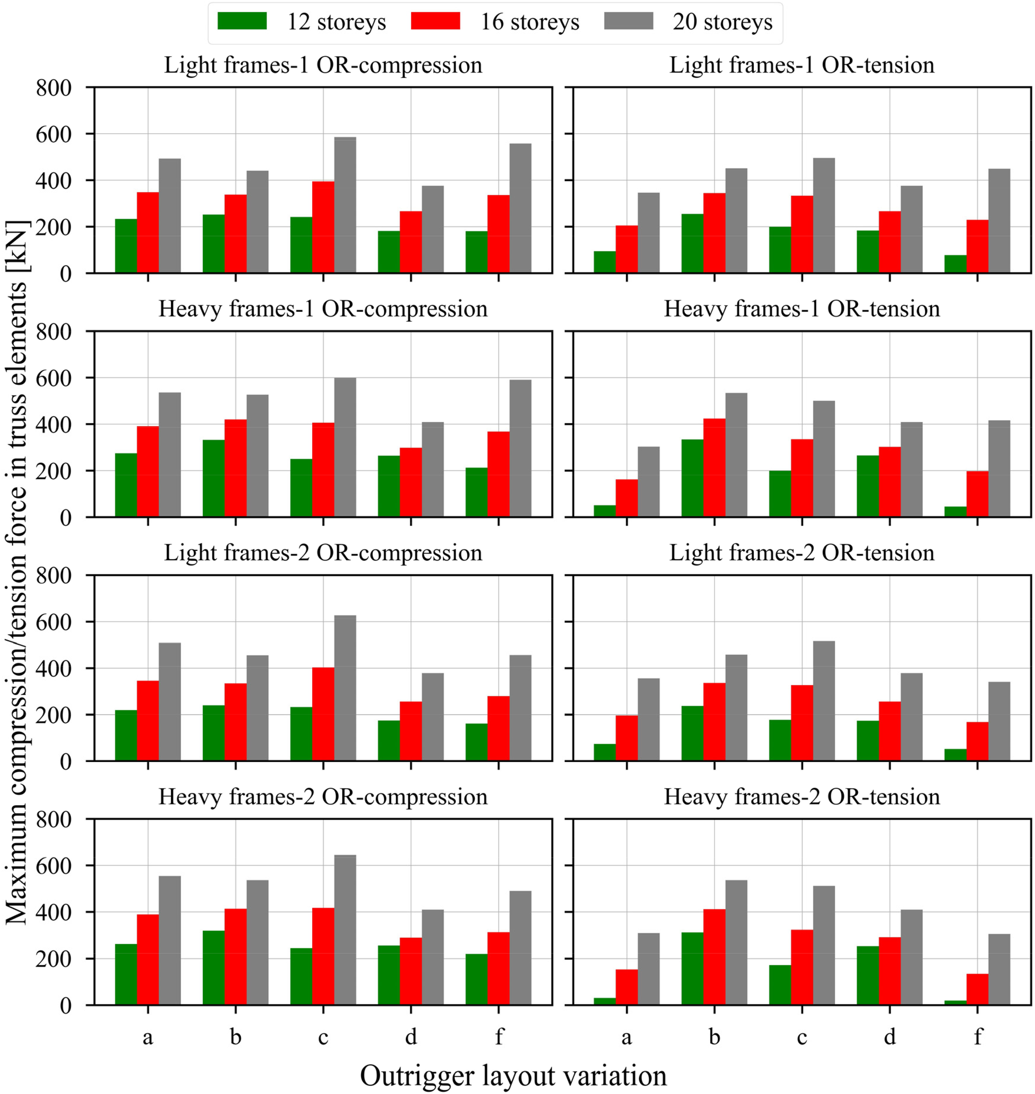
Force levels at the truss elements (
As shown in Figure 18, the force levels are quite high for the case of 20 storeys (grey bar), which imposes some challenges on the ULS with respect to cross-sections of the truss elements but mostly with respect to the connections to the main frame. To accommodate such force-level, the connections need to have a sufficient capacity which can be challenging. Among the five variations (a, b, c, d, f), the force-levels in variation (c) tends to be higher. Variation (c) has also the most slender truss elements and buckling may be critical.
For all variations except variation (e), and for the cases of 12 and 16 storeys, the values of the axial forces are in the order of 400 kN (200 kN per cross-section) and therefore these cases are deemed more feasible. Variation (e), on the other hand, can provide uniform distribution of forces between the OR and the main structure along the CLT panels perimeter. Therefore, even though variation (e) is less effective with respect to SLS compared to some other variations (see subsection ‘Comparison of outrigger variations’ in this article), it might be advantageous with respect to ULS to avoid force concentration at the connections.
Variation of connections stiffness and outrigger stiffness
Inherent variability in timber connections can lead to variations in the internal forces and moments of MRTFs.
52
In this subsection, the same benchmark frame in subsection ‘Stresses in an example frame’ is used to examine the effect of stiffness variability on the internal forces of the outrigger truss elements, lateral displacements and accelerations. A normal distribution with 20% coefficient of variation was assumed for The mean value of top floor displacement (obtained from the 3000 analyses) is 1.02% higher than the reference case (which assumes mean The mean value of IDR is 1.20% higher than the reference case. The mean value of peak acceleration is 0.53% higher than the reference case. The 95% percentile of the normal force of the outrigger truss elements is 8% higher than the reference case. The use of 98% results in 10% increase in the force.
While mean lateral displacements and accelerations exhibit negligible increase, there is a more noticeable increase in outrigger forces, which should be considered in the design for the ULS. The variation in connection stiffness of MRTFs has also been shown to have an insignificant influence on lateral displacements and accelerations.
52
Conclusions
In this article, the feasibility of using timber outrigger structures to build up to 20 storeys was investigated using linear elastic finite element analysis together with the relevant European and international standards. The feasibility is evaluated assuming wind velocities up to 30 m/s. The optimum location of one and two outriggers was estimated considering three criteria, namely: top floor displacement, inter-storey drift and wind-induced acceleration. Different layouts of outrigger were investigated, and their efficiency was compared. The stiffness of the outriggers was varied to evaluate the stiffness requirements. The influence of connections’ stiffness variability was also investigated. Although the focus of this article was devoted to serviceability requirements, some ULS considerations were briefly discussed. The following main conclusions are drawn:
Using one outrigger, a reduction of 30% to 65% in lateral displacements (top floor displacement and inter-storey drift) and 15% to 40% in wind-induced acceleration can be achieved. Using two outriggers, a reduction of 45% to 75% in lateral displacements and 25% to 55% in wind-induced acceleration can be achieved. Considering serviceability requirements, building up to 16 storeys is feasible with basic wind velocity of 26 to 30 m/s. Building 20 storeys is, however, challenging and can be limited to low basic wind velocities. Considering ultimate limit state, building up to 16 storeys is feasible. However, for 20 storeys, the forces in the connections can be challenging to design. Variability of connections’ stiffness has negligible influence on lateral displacements and wind-induced acceleration. On the other hand, an increase on the order of 10% in the force in the outrigger truss elements was observed compared to the reference value obtained using mean stiffness values.
Footnotes
Declaration of conflicting interests
The authors declared no potential conflicts of interest with respect to the research, authorship and/or publication of this article.
Funding
The authors received no financial support for the research, authorship and/or publication of this article.