
Abstract
Silk fibroin is commonly used as scaffold material for tissue engineering applications. In combination with a mineralization with different calcium phosphate phases, it can also be applied as material for bone regeneration. Here, we present a study which was performed to produce mineralized silk fibroin scaffolds with controlled macroporosity. In contrast to former studies, our approach focused on a simultaneous gelation and mineralization of silk fibroin by immersion of frozen silk fibroin monoliths in acidic calcium phosphate solutions. This was achieved by thawing frozen silk fibroin monoliths in acidic calcium phosphate solution, leading to the precipitation of monocalcium phosphate within the silk fibroin matrix. In the second approach, a conversion of incorporated β-tricalcium phosphate particles into brushite was successfully achieved. Furthermore, a controlled cryostructuring process of silk fibroin scaffolds was carried out leading to the formation of parallel-oriented pores with diameters of 30–50 µm.
Introduction
Silk proteins are produced in silk glands of silk worms or spiders and cocooned during metamorphosis to silk fibers.1–3 They are composed of two self-assembled protein components: (1) silk fibroin with 70–75 wt% represents the main part which is surrounded by a common cover of (2) 25–30 wt% sericin (silk glue) as second protein fraction.4,5 An important feature of silk fibroin is the high biocompatibility. 6 Since 1993, silk fibroin is a Food and Drug Administration–approved biomaterial, which can be used, for example, as suture material or as scaffold material (SERI® Surgical Scaffold) for the reinforcement and repair of soft tissue. 7 Silk fibroin scaffolds can be easily produced from silk fibroin solution by inducing a gelation reaction, which can be promoted via ultra-sonication, freeze-drying, vortexing or dehydrating agents since these methods lead to transition from a random coil structure into more stable β-sheets.8–11 Material properties of silk constructs vary depending on the production technique, the composition, the stiffness of the matrix, the amount of β-sheets and the scaffold morphology and topology. 12 The big goal is the maintenance of the stiffness properties of natural silk by manipulation of the structure during the production processes and thus the imitation of the values of native floss.13–15
Silk fibroin solutions are the basic raw material for silk-based systems like films, hydrogels and scaffolds. 16 The advantage of such solutions is the fabrication and processing under mild conditions, for example, room temperature, neutral pH-conditions and without application of shear stress. 17 This enables the incorporation of sensitive materials like drugs18,19 or organic (cells, proteins, enzymes) and inorganic (metallic nanoparticles, laser dyes) substances. Silk fibroin is water-soluble in its α-helical and random coil conformation. This water-solubility depends on the storage temperature, the pH-value, and the concentration of the solution, which is stable for several days to weeks. 20 The gelation occurs without addition of gelling agents due to the domination of hydrophobic amino acid groups. 21 Here, a sol-gel transition is induced by a conformational change from random coil and α-helical conformation to the more stable β-sheet form, which results in cross-linking and stabilization of the gel.22,23 The pH-value, temperature, and ionic strength of, for example, calcium ions, are influencing factors on the gelation of silk fibrion. Also, the production method of the gels has an effect on properties and hydrogel formation. A special form is the freeze-gelation technique, in which a frozen silk fibroin solution is stored in a suitable solution under freezing temperature. 24 Gels produced in such fashion have interesting mechanical properties with a good elasticity and a compressive strength of 50 MPa. 25
An important research area is the use of silk fibroin scaffolds for bone regeneration. Ribeiro et al. developed a system of silk fibroin-hydroxyapatite scaffolds and reached a higher osteoconductivity in comparison with unmodified silk fibroin scaffolds. They produced composite-hydrogels based on silk fibroin gels with ethanol as gelling agent and embedded hydroxyapatite-nanoparticles. This increased the compressive strength and decreased the water absorption. Furthermore, an improved activity of metabolic and alkaline phosphatase of osteoblasts was observed. 26 This study showed the positive effect of mineralized silk fibroin scaffolds for bone regeneration, in which silk fibroin offers both, the possibility for bone cell proliferation and for calcium phosphate deposition. 27 In a few recent studies, silk fibroin was combined with calcium phosphates such as hydroxyapatite (Ca5(PO4)3OH) or brushite (CaHPO4*2H2O, DCPD). The latter has the big advantage of an improved resorption under physiological conditions compared to hydroxyapatite-based materials 28 and is part of bone, fracture callus, and calculus. 29 The synthesis of brushite occurs at acidic conditions (pH 4–5) by either precipitation from solution or by a cement setting reaction. 30 This was investigated by Schamel et al., who developed a dual-setting-system based on brushite-forming cement and an aqueous silk fibroin solution. Due to the acidic setting conditions and an increased release of Ca2+-concentration, silk fibroin gelation is induced by a conformation change of the silk fibroin after mixing cement powder and silk fibroin solution. This forms interpenetrating silk fibroin–brushite networks, in which the shrinkage of silk fibroin during gelation leads to porosity reduction and intrinsic pre-stressing with an increased strength and improved toughness of the composites. 31 However, processing was only possible in the form of dense monoliths without the ability to create macropores for cell infiltration.
This study aimed to produce mineralized silk fibroin scaffolds with controlled macroporosity. In contrast to former studies, our approach focused on a simultaneous gelation and mineralization of silk fibroin by immersion of frozen silk fibroin monoliths in acidic calcium phosphate solutions. Here, the acidic pH leads to silk fibroin gelation during thawing of the silk fibroin samples by protonation of the carboxyl groups, which reduces electrostatic repulsion of silk fibroin chains and induces gelation. At the same time, the protonation of the amino acids leads to a protein folding from random coil to β-sheet, which is linked with an exclusion of water. Furthermore, a controlled macroporosity was introduced by cryostructuring with an anisotropic temperature gradient within the sample. The materials were characterized by measuring their mechanical properties and morphology depending on silk fibroin concentration and immersion conditions. The mineralization process was followed by X-ray diffraction (XRD) analysis demonstrating the formation of both, primary and secondary calcium phosphate phases.
Materials and methods
Production of silk fibroin solutions
The silk fibroin solution was produced by cutting 30 g of silk cocoons (Seidentraum, Leipzig, Germany) in small pieces and elimination of the silkworms. In order to remove sericin, the cocoons were immersed in 1.5 L of a 0.2 wt% sodium carbonate solution (Na2CO3; Merck KGaA, Darmstadt, Germany) and heated up to 80°C for 1 h. Afterwards, they were washed two times with 1.5 L hot (80°C) demineralized water. The product was dried overnight in a drying chamber (Memmert, SLE 500, Schwabach, Germany) at 60°C. In a second step, the purified silk was dissolved in 200 mL of a 9.3-M lithium bromide solution (Sigma Aldrich, Steinheim, Germany) and incubated for 3 h in a drying chamber (Memmert, SLE 500) at 60°C. Bigger particles of remaining silkworms were removed and the solution was dialyzed using dialysis tubes with a MWCO of 3500 Da (Carl Roth, Karlsruhe, Germany) against 9 L of demineralized water. The end of the process was defined by a conductivity lower than 10 µS (ExStick TDS meter; ExTech, Hamburg, Germany). After dialysis, the silk fibroin solution was transferred into falcon tubes and centrifuged for 10 min at 4500 r/min (Sigma 3_16K, Sigma Laborzentrifugen GmbH, Osterode am Harz). The solution was stored in the fridge at 5°C and the concentration of silk fibroin was determined by dry weight loss of 1 mL solution (concentration: w/v% abbreviated as %). In addition, the pH of the solutions was measured using a pH-meter (InoLab Level 1 WTW, Weilheim, Germany).
The final concentration of the so produced stock silk fibroin solution was about 4%. For the study, three different concentrations were used: (1) 2%, (2) 4%, and (3) 8%. The silk fibroin solution with a concentration of 2% was produced by a 1:1 dilution of the stock solution with demineralized water. The higher concentrated solution with 8% was produced by dialysis (dialysis tubes with MWCO of 3500 Da; Carl Roth) against a 20 wt% poly(ethylene glycol) solution (PEG, 20,000 Da; Merck) for 7.5 h.
Fabrication of silk fibroin scaffolds
Silk fibroin solutions with different concentrations were pipetted in petri dishes. Regarding the cryostructuring process and the compressive strength testing, samples were prepared in petri dishes with a diameter of 35 mm and a height of 10 mm (V = 6 mL). The tensile strength was investigated using specimens with bigger dimensions which were produced in petri dishes with a diameter of 94 mm and a height of 16 mm (V = 30 mL). The samples were placed horizontally in a freezer at −20°C. The frozen small samples (ø = 35 mm) were incubated in 100 mL of a 2.5 wt% or 5 wt% solution of anhydrous monocalcium phosphate (MCPA; Budenheim, Budenheim, Germany) acidified with 2 mL of ortho-phosphoric acid 85% (Merck). The bigger silk fibroin scaffolds (ø = 94 mm) were immersed in 200 mL of MCPA-phosphoric acid solution. All samples were stored for 3 or 6 days in the phosphate solution.
Synthesis of β-tricalcium phosphate
β-Tricalcium phosphate (β-TCP, Ca3(PO4)2) was prepared by sintering dicalcium phosphate (CaHPO4; Mallinckrodt-Baker, Renningen, Germany) and calcium carbonate (CaCO3; Merck) in a molar ratio of 2 to 1 for 5 h at 1050°C following quenching to room temperature. The sintered cakes were crushed and passed through a 355-μm pore size sieve followed by milling with a planetary ball mill (Retsch Technology GmbH, Haan, Germany) at 200 rpm for 60 min.
Particle size analysis
β-TCP and MCPA were analyzed regarding their particle size using the Laser Scattering Particle Size Distribution Analyzer LA 300 of Horiba (Retsch Technology GmbH). A spatula tip of the sample was placed in 2-propanol (VWR Chemicals, Ismaning, Germany) and an ultrasonication bath Sonorex (BANDELIN electronic GmbH & Co. KG, Berlin, Germany) for a homogeneous distribution of the particles.
Fabrication of brushite-silk fibroin scaffolds
Silk fibroin solution of 4 mL (4%) was pipetted in a small petri dish (ø = 35 mm) and β-TCP of 1 g was mixed to the solution while stirring with a magnetic stir bar. The β-TCP-silk fibroin suspension was stored horizontally in the freezer at −20°C for 1 day. The samples were lyophilized for 3 days using a freeze-drying device (Alpha 1-2 LD; Christ, Osterode am Harz, Germany). Afterward, the scaffolds were stored in 20 wt% phosphoric acid (Merck) in a certain interval process (1 min phosphoric acid, 15 min storage out of the solution, 1 min phosphoric acid, 15 min storage out of the solution, 1 min phosphoric acid) and dried at room temperature for 3 days with a following drying interval in the drying chamber (Memmert, SLE 500) at 37°C for 1 h.
Compressive strength testing
The silk fibroin scaffolds (ø = 35 mm, V = 6 mL) were cut with a biopsy skin puncher in seven specimens with a diameter of 8 mm and measured under wet conditions in a petri dish covered with 1 mL demineralized water. The compressive strength measurements were performed with the dynamic mechanical analysis device Bose ElectroForce 5500 (Bose, Friedrichsdorf, Germany) and a 22-N load cell. The samples were placed on the support of the device until a pre-load of 0.05 N was reached and the force was reset for the measurement. Table 1 gives an overview of the calculated parameters.
Calculated parameters of compressive strength testing and the corresponding equations.

For static compressive strength testing, samples with all three different concentrations (2%, 4%, and 8%) were analyzed. The chosen crosshead speed for the measurement was 0.01 mm/s and the maximum compression was selected with 1.5 mm. The tested samples for the dynamic measurements had a silk fibroin concentration of 4%. The chosen speed was 0.1 mm/s and the measuring process was as follows: 1000 measuring cycles were programmed with a starting value of 0.1 mm for 10 s. After this plateau, the cycles started with a maximum range of 1.5 mm. The cycles 0–10, 100–110, 500–510, and 1000–1010 were recorded.
Tensile strength testing
For the tensile testing, the silk fibroin scaffolds (ø = 94 mm, V = 30 mL) were cut with scissors into 10 rod-shaped specimens with a minimum length of 5 cm and a width of 6 mm. All three different concentrations of the silk fibroin solution (2%, 4%, and 8%) were incubated in acidic MCPA solutions (2.5 wt% and 5 wt%). The test was carried out using the static mechanical testing machine Z010 (Zwick/Roell, Ulm, Germany) with a 200-N load cell. The samples were fixed with tape and superglue at both ends. The distance between the fixing units was adjusted to 9 mm before measurement. The tests were performed with a crosshead speed of 12.5 mm/min and a pre-load of 0.1 N. Table 2 gives an overview of the calculated parameters.
Calculated parameters of tensile strength testing and the corresponding equations.

X-ray diffraction analysis
The phase composition of the silk fibroin scaffolds was analyzed using the X-Ray-Diffractometer D5005 (Siemens, Munich, Germany). XRD patterns of samples were carried out with monochromatic Cu Kα radiation. Data were collected from 2θ = 10°–60° (MCPA-silk fibroin samples) and 2θ = 20°–40° (β-TCP-silk fibroin samples) with a step size of 0.02° and a normalized count time of 3 s per step. Phase composition was checked by means of JCPDS reference patterns for brushite (PDF Ref. 09-0077, CaPO3(OH)·2 H2O), monetite (PDF Ref. 09-0080, CaPO3(OH)), β-TCP (whitlockite, PDF Ref. 09-0169, Ca3(PO4)2), and MCPA (PDF Ref. 09-0347; Ca(H2PO4)2). The samples were dried at 60°C in a drying chamber (Memmert, SLE 500) prior to the XRD analysis and crushed using mortar and pistil in a first step and a coffee grinder in a second step.
Fourier-transform infrared spectroscopy
Fourier-transform infrared (FTIR) spectra for the verification of the silk fibroin gelation were recorded using a Nicolet™ iS™ 10 spectrometer (Thermo Fisher Scientific, Waltham/Massachusetts, USA) in the spectral region of 4000–650 cm−1 via attenuated total reflection mode.
Scanning electron microscopy
Scanning electron microscopy (SEM) images were recorded with a scanning electron microscope (CB 340, Zeiss, Oberkochen, Germany) with an acceleration voltage of 2.0–5.0 kV. The samples were prepared using a ceramic knife and sticking small pieces on self-adhesive stripes on the SEM plates. For a better electrical conductivity, the surface of the samples was sputtered with a 4-nm-thick platinum layer using the High Vacuum Coater Leica EM ACE 600 (Emitech, Molfetta, Italy).
Mercury intrusion porosimeter
Porosity characteristics of the silk fibroin scaffolds were analyzed using a Mercury Intrusion Porosimeter of the Pascal 140 and 440 series (Thermo Finnigan; Thermo Fisher Scientific).
Cryostructuring of silk fibroin scaffolds
In addition to isotropic freezing, the silk fibroin solutions were structured by using a defined temperature gradient (T-gradient with a home build apparatus based on two Peltier elements that allow for adjustment of distinct temperature difference for oriented freezing (adjustable cryostructuring device (ACD) 5.0; University of Würzburg, Würzburg, Germany). 32 The T-gradient between the upper Peltier element (T = 27.5°C) and the lower Peltier element (T = –49.2°C) was adjusted to ∇T = 5.5 K*/mm-1. Afterward, 4 mL silk fibroin solution was pipetted in a petri dish (ø = 35 mm, h = 10 mm), placed in the device, and the cryostructuring process was started after closing the cover. The procedure was stopped after the sample temperature reached a plateau (defined as no temperature change of the sample for 30 s). The cryostructured scaffolds were stored in a freezer at −20°C before lyophilization for 4 days with a freeze-drying device (Alpha 1-2 LD; Christ). The samples were analyzed using SEM (see section “Scanning electron microscopy”).
Statistical analysis
Statistical analysis of data was performed by analysis of variance (ANOVA) using the statistical software package SigmaPlot (Systat Software, Erkrath, Germany; version 12.5). Differences between groups of p < 0.001 were considered to be highly statistically significant and for p < 0.005 as statistically significant.
Results
Characterization of the silk fibroin solution
Silk fibroin is a natural product and has a certain variability concerning the production of solutions. Reproducible batches (10 produced) were made with concentrations of about 2%, 4%, and 8% silk fibroin. The determination of the silk fibroin amount led to values of 2.01 ± 0.22%, 3.89 ± 0.55%, and 7.77 ± 0.45%. The measured pH-value increased with higher silk fibroin concentration with 7.07 ± 0.07 for 2% silk fibroin concentration, 7.35 ± 0.10 for 4% silk fibroin concentration, and 7.41 ± 0.08 for 8% silk fibroin concentration.
Characterization of β-TCP- and MCPA-particle size
The size of the used MCPA was in the range of D50 = 19.78 ± 3.1 µm. In addition, the β-TCP raw powder for the conversion to brushite was analyzed and showed particle sizes of D50 = 7.85 ± 0.1 µm (Figure 1(a) and (b)). During the production process of the silk fibroin scaffolds, MCPA was completely dissolved in the acidified solution. Concerning β-TCP, the size was analyzed with respect to the observed sedimentation during freezing. Here, the sedimentation might be minimized in further studies by using fibroin solutions with higher viscosity or by increasing milling time to further reduce β-TCP particle size. The latter is very important regarding sedimentation processes based on Stokes’ law, where the radius of the particles affects the sedimentation velocity as squared variable.
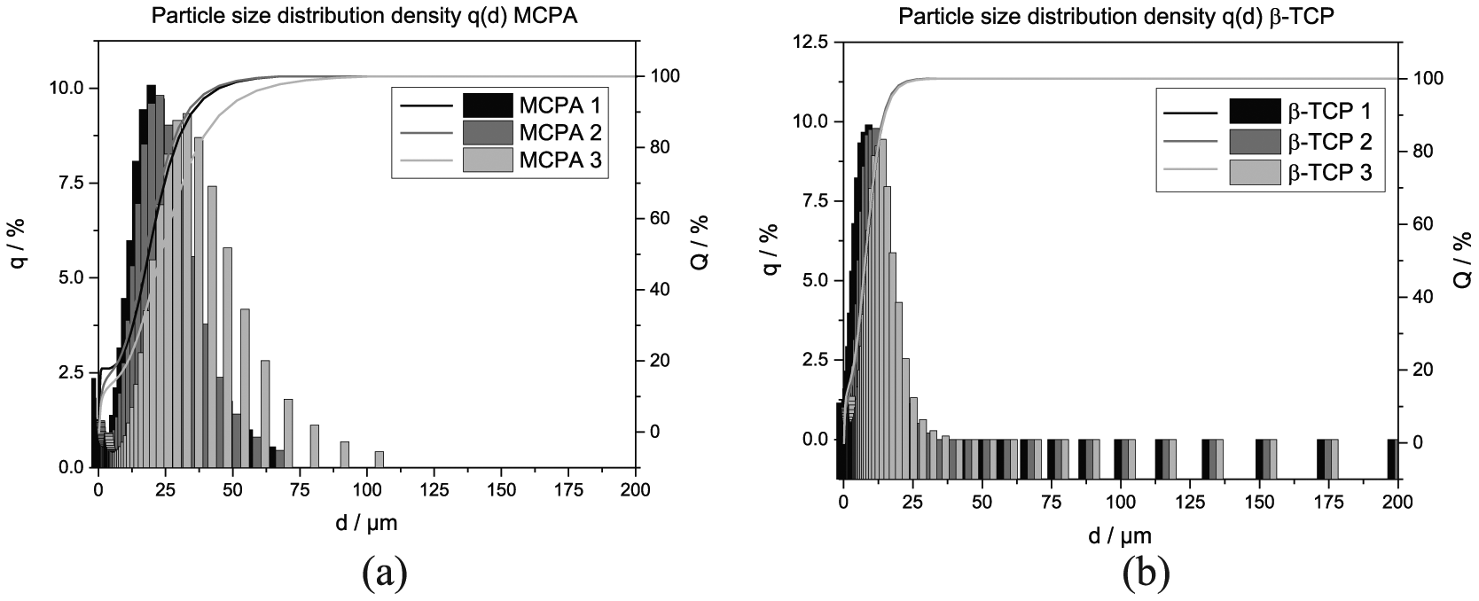
Results of the particle size analysis for (a) MCPA and (b) β-TCP. The measurements were performed due to the precipitation of MCPA on the silk fibroin scaffolds as well as the sedimentation of brushite in silk fibroin solution with afterward conversion to brushite.
Characterization of the MCPA-silk fibroin scaffolds
Compressive strength
The stress–strain curves of the static compressive strength testing as well as the calculated E-moduli of the silk fibroin scaffolds with different concentrations are shown in Figure 2. Regarding the compressive strength, the values were between 5 and 120 kPa with an increase in compressive strength at higher silk fibroin concentration. For the silk fibroin scaffolds with a concentration of 2%, levels in a range of 5–10 kPa were reached. The samples produced out of 4% silk fibroin solution showed a compressive strength of 10–20 kPa. Another doubling of the concentration led to very high values of compressive strength with 90–120 kPa. There was also an increase in stress with a higher immersion time in acidic MCPA solution from 3 to 6 days (Figure 2(a) and (b)). The scaffolds with 4% silk fibroin concentration and an incubation time of 3 and 6 days in 5 wt% MCPA-phosphoric acid solution showed relatively constant stress values. The amount of MCPA had no influence on the compressive strength, whereas the strain decreased with an increasing MCPA concentration (5 wt% < 2.5 wt%). The highest stretching could be observed for the silk fibroin scaffolds with 8% and an incubation time of 3 days in 5 wt% acidic MCPA solution. In general, the strain decreased with higher silk fibroin concentration and longer incubation time (Figure 2(a) and (b)). The E-moduli of the scaffolds with 2% silk fibroin concentration were in the range of 8.7–17.8 kPa (Figure 2(c)). The samples produced out of 4% silk fibroin solution led to E-moduli between 42.8 and 46.8 kPa, whereas the specimens of 8% silk fibroin concentration led to the highest values of 500.5–677.8 kPa. The amount of MCPA had no influence on the value of the E-moduli.

Stress–strain curves of the silk fibroin scaffolds (2%, 4%, and 8% silk fibroin) and the two different concentrations of MCPA-phosphoric acid solution (a: 2.5 wt% MCPA solution; b: 5 wt% MCPA solution). Graph (c) shows an overview of the E-moduli for all batches at different time points (d = 3; d = 6).
Scaffolds with a silk fibroin concentration of 4% and an incubation of 3 days in 2.5 wt% MCPA-phosphoric acid solution were also tested under dynamic conditions. The scaffolds were stored in demineralized water due to the long cyclic measurement for several hours. Figure 3 gives an overview of the dynamic compressive testing. At the beginning of the measurement (cycles 0–10; Figure 3(a)), the stress values were higher compared to cycle 1000–1010 (Figure 3(b)). The shift of the hysteresis slope was observed at the beginning and reached a certain equilibrium over the time. The maximum of the curve was about 13 kPa and nearly congruent.

Stress–strain curves of the dynamic compressive strength testing for a scaffold with 4% silk fibroin incubated in 2.5 wt% MCPA-phosphoric acid solution for 3 days. (a) First 10 cycles under dynamic conditions. (b) An overview of three different cycles (numbers 100, 500, and 1000, respectively) for 10 repeating compressions.
Tensile strength testing
The stress–strain curves for all formulations are shown in Figure 4. Graph a gives an overview of the samples placed in a 2.5 wt% MCPA-phosphoric acid solution for 3 days (Figure 4(a)). For these batches, the tensile strength was in a range of 20–130 kPa. An incubation time of 6 days led to values between 15 and 150 kPa (Figure 4(b)). For both time points, an increase in stress could be observed with increasing silk fibroin concentration. In contrast, a strain reduction was noticed for higher silk fibroin content. In general, the tensile strength increased with prolonged incubation of the scaffolds in MCPA solution which means from 3 to 6 days about 20% for 4% and 35% for 8% silk fibroin concentration. The scaffolds with a silk fibroin concentration of 2% placed in the 5 wt% MCPA solution differ from the trend of the other concentrations. A decrease in tensile strength was observed after a strain >0.2.

Stress–strain curves of the silk fibroin scaffolds (2%, 4%, and 8% silk fibroin) and the two different concentrations of MCPA-phosphoric acid solution for the tensile strength testing (a: 2.5 wt% MCPA solution; b: 5 wt% MCPA solution). Graph (c) shows an overview of the E-moduli for all batches at different time points.
The E-moduli increased with increasing silk fibroin concentration. The scaffolds with 2% silk fibroin concentration were in the range of 0.4–0.8 kPa. A doubling of the silk fibroin content led to values between 1.8 and 2.8 kPa. The highest silk fibroin concentration (8%) resulted in E-moduli of 4.1–6.9 kPa (Figure 4(c)). An additional influencing parameter on the E-moduli was the incubation time (6 days > 3 days). The deviation of the stress–strain curves regarding the batch with 2% silk fibroin concentration in 5 wt% MCPA solution was also seen for the calculation of the E-moduli. In comparison with the incubation time (3 or 6 days), the amount of MCPA (5% > 2.5%) had more effect on the values of the tensile strength.
Analysis of mineral phase composition via XRD and silk fibroin gelation via FTIR
The mineralization and phase composition of the scaffolds after immersion in the MCPA-phosphoric acid solution were analyzed via XRD. The parameters were varied regarding the MCPA concentration (2.5% vs 5%) and an incubation time of 3 or 6 days. The scaffolds were measured wet which means immediately after storage in the solution, as well as after drying overnight in the drying chamber at 60°C.
For the measurement of the wet samples, no diffraction patterns could be detected (Figure 5(a)). After drying and grinding of the same scaffolds (Figure 5(b)), sharp diffraction signals were detected in the range of 22°–25°, which were assigned to the deposition of MCPA in the silk fibroin scaffolds. Dry samples of all three silk fibroin concentrations (2%, 4%, and 8%) after 3 days of storage in 5 wt% MCPA-phosphoric acid solution showed diffraction patterns with a higher intensity in comparison with incubation in 2.5 wt% MCPA solution (Figure 5(b) vs (c)). A higher MCPA concentration had more influence on the diffraction intensity in comparison to the incubation time (Figure 5(c) vs (d)).

XRD patterns of the silk fibroin scaffolds (*diffraction pattern of MCPA) produced from 2%, 4%, and 8% silk fibroin solution in either (a, b) 2.5 wt% or (c, d) 5 wt% MCPA solution.
The structural confirmation change from α-helical/random coil structures to β-sheet-conformations was investigated via FTIR. Characteristic absorption bands in the FTIR spectrum can be assigned to each conformation status. The signals that can be associated with the β-sheet confirmation of silk fibroin are ~ 1630, 1530, 1265 and 700 cm−1 while the peaks at about 1660, 1540 and 1235 cm−1 are related to α-helical/random coil structures. 33 Exemplary, the silk fibroin solution with a concentration of 4% was compared with lyophilized silk fibroin solutions without water content (Figure 6(a)) and all different batches immersed in acidic MCPA solution with 2.5 wt% or 5 wt% for 3 days (Figure 6(b)). Next to the wet measurement of the incubated scaffolds, they were also analyzed after lyophilization (Figure 6(c)) showing the characteristic signals for the β-sheet conformation which verifies the gelation of silk fibroin after incubation in the mineralization solution.
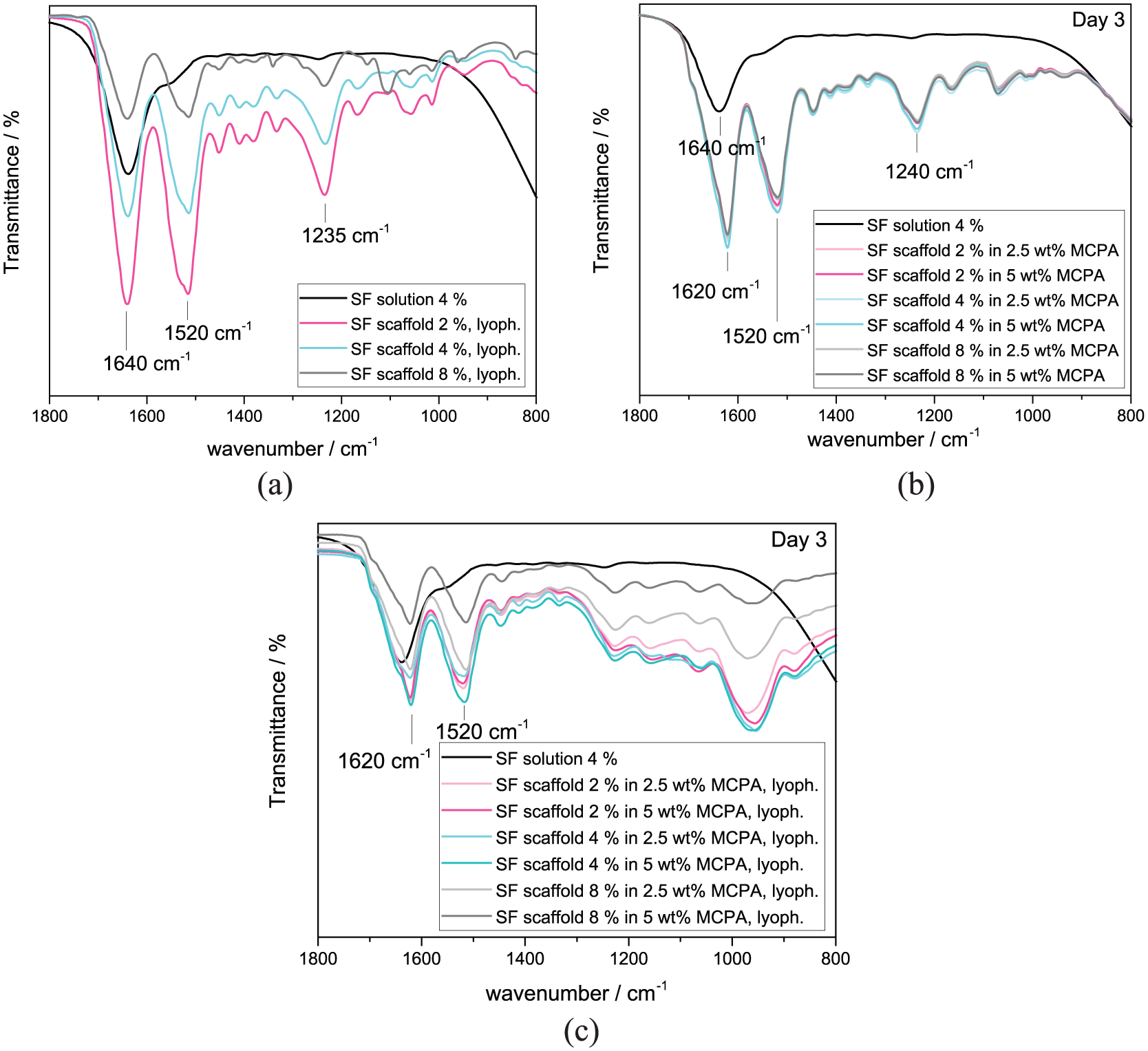
FTIR spectra of the pure silk fibroin solution (4%) compared with lyophilized scaffolds in all three different concentrations in order to analyze the signals related to the α-helical/random coil conformation (a) without water bands. Furthermore, also the mineralized scaffolds were measured after 3-day incubation in (b) acidic MCPA solutions (2.5 wt% and 5 wt%) and (c) after lyophilization.
Surface and porosity characterization of freeze-dried silk fibroin solutions in comparison with MCPA-silk fibroin scaffolds
The surface and the bulk volume of freeze-dried scaffolds produced from a 4% silk fibroin solution were compared with the surface of the MCPA-silk fibroin scaffolds (4% silk fibroin in 2.5 wt% MCPA-phosphoric acid solution). In Figure 7(a) and (b), the smooth surface of a dried silk fibroin scaffold is depicted. The freeze-dried solutions showed a homogeneous, smooth structure with regularly arranged notches which were oriented to the inner scaffold part. The big pores are generated due to the lyophilization process and the consequent loss of ice crystals that generates pores. The amount and size of the porous structures depend on the concentration of the silk fibroin solution, with a higher amount of silk fibroin, leading to less pores with smaller diameters. A closer look to the bulk volume showed lamellar structures that are interconnected, which should support cell growth into the scaffold (Figure 7(c)).

SEM images depicting surface and inside of scaffolds with 4% silk fibroin with and without mineralization, respectively. Images (a–c) show as reference a freeze-dried silk fibroin solution (a + b = surface, c = inside area), images (d)–(f) illustrate the surface of a MCPA-silk fibroin scaffold, whereas images (g)–(i) depict the inside area of a MCPA-silk fibroin scaffold.
Contrary to this smooth texture, the MCPA-silk fibroin scaffolds had a rough and inhomogeneous surface with scattered notches (Figure 7(d)–(f)). The highest magnification clearly shows the MCPA-deposition on the scaffold surface (Figure 7(f)). The SEM images of the inner (cut) surface showed the same trend (Figure 7(g)–(i)).
The analysis of the pore size of the silk fibroin scaffolds showed bigger pore diameters with increasing silk fibroin concentration (Figure 8(a)–(c)). However, there is also a network structure in a second level with smaller pores that were not measurable with the Mercury Porosimeter for the samples with 4% and 8% silk fibroin content though to detection limit. This was verified by the SEM image of the specimen in Figure 7(i). For the silk fibroin concentration of 2%, the sum of the measurements of both, bigger and smaller pore sizes of a scaffold is depicted in Figure 8(a).

Pore distribution of silk fibroin samples with a silk fibroin concentration of (a) 2%, (b) 4%, and (c) 8%.
Characterization of brushite-silk fibroin scaffolds
For the mineralization of brushite-silk fibroin scaffolds, samples of 4% silk fibroin solution were mixed with β-TCP and immersed in 20 wt% phosphoric acid. The scaffolds were frozen or freeze-dried and placed in the solution to start the setting reaction to brushite.
The lyophilized scaffold showed brushite, MCPA and residues of β-TCP. The frozen silk fibroin scaffold which had been incubated in certain interval steps showed the highest intensity of brushite diffraction pattern (Figure 9). The distribution of the brushite crystals and their structure was additionally analyzed using SEM. Figure 10 gives an overview of the images.

XRD pattern of the mineralized brushite silk fibroin scaffolds in a range of 20°–40° (*diffraction pattern of MCPA, b = diffraction pattern brushite, w = diffraction pattern β-TCP/whitlockite) for phase analysis of a frozen as well as freeze-dried brushite-silk fibroin scaffold (4%) after interval incubation in 20% phosphoric acid.

SEM images of the bottom side of a freeze-dried brushite-silk fibroin (4%) scaffold which was incubated (a–c) in phosphoric acid in small intervals. Picture (d) gives an overview of the scaffold cross section with bottom side (BS) and top side (TS).
Most of the brushite crystals were located on the bottom side (BS; Figure 10(a) and (b)) of the scaffold instead of the top side (TS). This fact is based on the inhomogeneous suspension of β-TCP-powder in the silk fibroin solution (4%). A sedimentation of the solid phase occurred on the ground of the petri dish because the solution was not stirred during the freezing process. With a higher magnification, the platelet layered structure of the calcium phosphate cement was observed (Figure 10(c)). The scaffold with brushite precipitation was analyzed also inside the specimen (Figure 10(d)), where crystalline structures could be observed.
Cryostructuring
The cryostructuring process via ACD was used in order to obtain vertically oriented lamellar porous structures. Between the generated channels, the structures can be described as oriented, inter-lamellar distances which can be used for guided cell ingrowth. For the production of scaffolds, three different concentrations (2%, 4%, and 8%) were used and analyzed via SEM.
The structures of the samples showed continuous channels between the silk fibroin lamellas of the scaffold. The distance between the lamellas for the specimens with a silk fibroin concentration of 4% and 8% was bigger in comparison with the 2% concentration and more stable during the cutting for sample preparation (Figure 11). The distance between the lamellar structures of the lowest concentrated specimens was not clearly measurable (about 19.3 ± 5.0 µm) due to the deformation of the sample during cutting with the knife. This might be an explanation for the quasi-vertical direction of the inner texture. Measurements of the inter-lamellar distance for the other silk fibroin concentrations resulted in values of 37.6 ± 8.2 µm for 8% silk fibroin and 60.6 ± 11.1 µm for 4% silk fibroin.
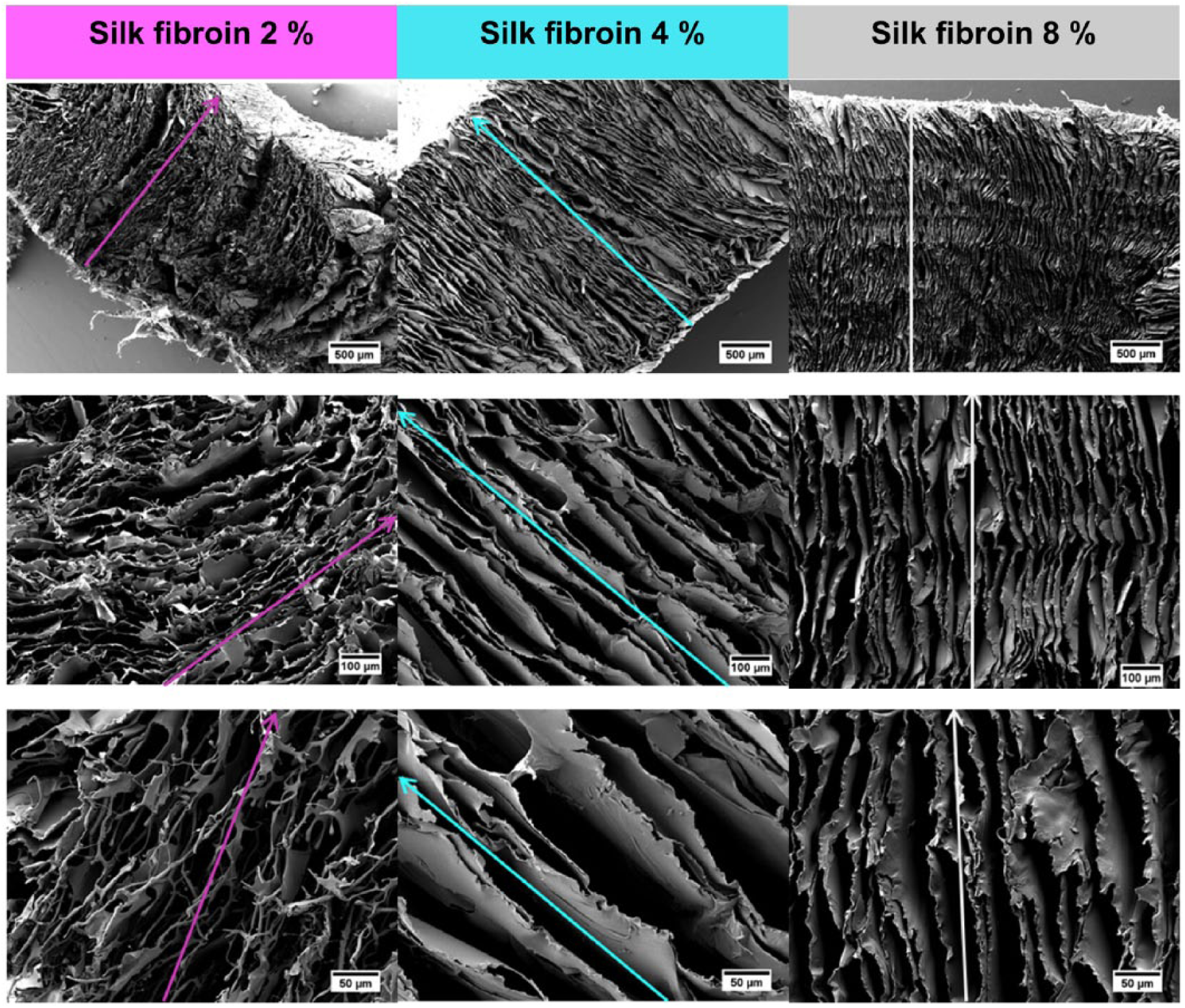
SEM images of the cryostructured samples with different silk fibroin concentrations (2%, 4%, and 8%). The colored arrows in the pictures show the vertically oriented inter-lamellar structures as well as the direction of the applied T-gradient.
Discussion
Reproducible batches of silk fibroin solution were prepared using cocoons of Bombyx mori. The immersion of the frozen silk fibroin scaffolds in MCPA-phosphoric acid solution resulted in the mineralization of MCPA. In addition, β-TCP powder was incorporated in the silk fibroin solution which led to its conversion to brushite parallel to the gelation of silk fibroin. Another aspect of this study was the development of a cryostructuring process for silk fibroin solutions to generate defined structured scaffolds with macropores.
The structural comparison of pure silk fibroin scaffolds and MCPA-silk fibroin scaffolds showed connected pores for both batches and mineral depositions for the specimens immersed in MCPA solution. According to the optical control via SEM, a foliaceous look was observed for the silk fibroin structures. After storage in MCPA-phosphoric acid solution, the constructs convert to defined porous patterns (Figure 7). The interconnectivity and formation of a porous network play an important role for the organization of seeded cells on the scaffold. Furthermore, the conversion is induced by the gelation of the scaffold which occurs at low pH levels and in the presence of calcium ions in the MCPA solution. Hereby, hydrophobic interactions and hydrogen bonds are formed and the conformation changes from random-coil to β-sheets. This process is correlated with water ejection. 22 The water between the new-formed crystalline structures diffuses out of the scaffold. This results in an inhomogeneous pore-distribution and spongy pore-network as described for silk fibroin hydrogels. 34 Incubating the frozen samples in a MCPA containing solution, a dense silk fibroin network was created. Such porous morphologies are suitable matrices for cell adhesion and cell growth and can serve as carrier materials. The diffraction patterns of dried MCPA-silk fibroin scaffolds are broad which indicates a low crystallinity and the existence of an amorphous phase before drying (Figure 5). During thawing of the sample, the solution penetrates through the scaffold and induces the gelation of silk fibroin from the outside to the inner core. The dissolved MCPA precipitates during the drying process and mineralizes the scaffold. In general, it is possible to incorporate a primary calcium phosphate in the scaffolds by using this gelation technique and controlling the amount of embedded MCPA by addition of different concentrations in the phosphoric acid solution. Clearly, a neutralization of these scaffolds has to take place prior to further cell testing or in vivo application. However, this can be performed via washing steps before cell culture in medium or phosphate buffered saline to remove acidic components.
The compressive modulus of the 2% silk fibroin scaffolds was in the range of 8.7–17.8 kPa. Furthermore, scaffolds made of 4% silk fibroin solution showed moduli in the range of 42.8–46.8 kPa. Referred to the high silk fibroin content, scaffolds with 8% silk fibroin reached the highest values (500.5–677.8 kPa) for the mechanical testing. The doubling of the MCPA-amount from 2.5 wt% to 5 wt% did not have any influence on the compressive strength levels or on the moduli. One explanation might be that MCPA has no effect on the hydrophobic interactions and hydrogen bonds of silk fibroin during compression. Assimilable values in the literature can be found for silk fibroin-hydrogels mineralized with hydroxyapatite. They showed compressive moduli from 92.2-109.8 kPa for samples with a silk fibroin concentration of 4%. In comparison, the E-modulus of their pure silk fibroin hydrogels was about 125 kPa. According to this study, the decrease in strength for the mineralized hydrogel samples was caused by a bigger pore structure and a lower silk fibroin content. 26
The modulus of our produced 4% MCPA-silk fibroin scaffolds without mineral phase (46.8 kPa) is reduced by more than 50% regarding the modulus of the hydroxyapatite-silk fibroin hydrogels. This could be explained by the different gelation methods. The production of the hydroxyapatite-based samples was performed via mixing of hydroxyapatite-nanoparticles with ethanol and afterwards mixing to silk fibroin solution. Consequently, the gelation was induced by the presence of alcohol. 26 In this study, hydrogel formation was triggered by the incubation of frozen scaffolds in acidic MCPA solution. The gelation method affects the conformation to β-sheets, the pore size and consequently the compressive modulus. 35 Another important fact, that influences the mechanical properties, is the freezing and gelation process of the silk fibroin solution. According to Ribeiro et al., 26 an increase in pore size and a strong decrease of the moduli of hydrogels which were frozen after gelation could be observed. In literature, a reduction of mechanical properties of silk fibroin with long storage time in water was reported. 36 We observed an increase in compressive and tensile strength of the MCPA-silk fibroin scaffolds with higher concentrations. This result can be explained by higher interactions between several silk fibroin molecules. Kim et al. also observed this trend. They used hydrogels which were formed by a temperature increase up to 60°C. 34 The higher content of silk fibroin led to more hydrophobic interactions and hydrogen bonds and consequently in a reduced strain. The effect can be explained by the stick-slip-effect. At the beginning of the deformation, shear movement occurs and hydrogen bonds are stressed. At this point, amino acid strands are able to slip and new hydrogen bonds can be formed. 37 With increased stretching, less space is given for the slipping of the amino acid strands and the sample breaks due to those steric hindrances. The space is reduced within nano-crystals and the strain-capability decreases corresponding to higher silk fibroin concentrations. Kim et al. 34 explained this phenomenon by the fact that smaller pore sizes can distribute the applied force on the sample much better and avoid the fracture expansion.
Regarding the mechanical properties of the here produced scaffolds, the storage time (3 or 6 days) influenced the stress and the E-moduli of the compressive and tensile strength testing and led to higher values. The longer incubation time might induce increasing formation of β-sheet-structures. It was observed that this had the most prominent effect on the samples produced out of 2% silk fibroin solution.
By mixing β-TCP in the silk fibroin solution, a brushite forming cement reaction was induced according to equation (7).

Diffractograms as well as SEM images verified the formation of brushite. The presence of 20% phosphoric acid induced the crystallization of brushite from β-TCP 38 as well as the silk fibroin gelation. 22 The crystal structures were found mainly on the bottom side (BS) of the scaffold. This is thought to be a result of an inhomogeneous β-TCP-silk fibroin suspension due to a sedimentation of the β-TCP powder in the petri dish. As an inhomogeneous distribution of calcium phosphates has an influence on the material properties, 26 this process has to be further optimized, for example, by adjusting the viscosity level of the silk fibroin solution which indirectly affects the sedimentation velocity of the particles or by increasing the powder-to-liquid ratio such that the mineral phase will be the dominant component in the scaffold next to silk fibroin. In the latter case, the pores can be clogged by the precipitated mineral, which might have a detrimental effect on cell ingrowth into the structures. However, due to the sufficient solubility of brushite under in vivo conditions, it is thought that the precipitates will subsequently dissolve and reopen the porous nature of the silk fibroin structure for cell ingrowth.
In this study, a simultaneous gelation and mineralization in a frozen scaffold was possible during thawing. Compared to other mineralized silk fibroin systems in the literature based on hydroxyapatite-silk fibroin hydrogel, 26 the use of our system for bone remodeling is likely advantageous due to the higher resorption rate of brushite in comparison with hydroxyapatite, which should enable a simultaneous material resorption and bone formation. 39 Although brushite is mechanically weaker than hydroxyapatite, this can be compensated by the very good mechanical properties of silk fibroin. 40 Combining both materials seems to be a promising tool for bone regeneration.
The cryostructuring process aimed to form continuous and aligned lamellar structures from the bottom to the top side (TS) of the scaffold along the temperature gradient. This anisotropic microporous structure promotes cell migration into the scaffold as already demonstrated in collagen-based scaffolds. 32 Smaller lamellas with different morphologies were observed for an increasing amount of silk fibroin. Thus, the size of the porous structures can be regulated directly which is an important fact for cell or capillary ingrowth. 41 Further developments might be directed to both, a simultaneous mineralization of the cryostructured scaffolds by using particle filled silk fibroin solutions and mechanically more stable scaffolds. Here, the use of a second hydrogel forming network is promising as shown by Ak et al., who developed a system for bone scaffold materials using silk fibroin cryogels with the addition of ethylene glycol diglycidyl ether (EGDE) to induce the transition to β-sheet structures. They used frozen fibroin solutions without any controlled freezing (between −5 and −22°C) and the addition of a cross-linker and a catalyst (N,N,N′,N′-Tetramethylethylenediamine (TEMED)) for the EGDE polymerization to hydrogels. This allowed the fabrication of very elastic samples without any crack development and with a compressive modulus of 50 MPa for scaffolds produced with 12.6% fibroin content. 25 In a following study, scaffolds with anisotropic hierarchical morphologies were investigated. Directional freezing and cryogelation were combined using a 4.2 wt% silk fibroin solution with butanediol diglycidyl ether and TEMED at −18°C. The scaffolds reached Young’s moduli in the range of 3.4 ± 0.5 MPa (measured parallelly to the direction of the freezing process). 42
Conclusion
This study was performed to develop and characterize structuring methods for silk fibroin scaffolds, which enable a simultaneous gelation and mineralization of silk fibroin. MCPA precipitation was observed after immersion of frozen silk fibroin scaffolds in acidic monocalcium phosphate solution with different amounts of MCPA and different incubation times. Subsequently to drying, a continuous porous structure with MCPA deposition occurred. A mineralization with brushite detected after incubation of the silk fibroin scaffold (4% silk fibroin) loaded with β-TCP particles in phosphoric acid solution. Furthermore, an automatic cryostructuring process was used to generate anisotropic porous structures in the scaffold. The samples showed a homogeneous pore distribution with a straight pore alignment along the T-gradient. Combining the mechanical properties and degradability of silk fibroin scaffolds, on one hand, and the osteoconductivity of calcium phosphates such as brushite, on the other hand, the materials from this study have potential as versatile tool for bone regenerative medicine. The mineralization strategy is not limited to calcium phosphates, but will also be applicable for magnesium phosphates, which are currently intensively discussed as a suitable alternative for bone replacements. 43
Footnotes
Declaration of conflicting interests
The author(s) declared no potential conflicts of interest with respect to the research, authorship, and/or publication of this article.
Funding
This work was supported by the Deutsche Forschungsgemeinschaft (DFG) under the grant number GB 1/20-1 and GR 3232/3-1. We gratefully acknowledge financial support by DFG State Major Instrumentation Program, funding the electron microscope Zeiss CB 340 (INST 1522/58-1 FUGG).