
Abstract
External building cladding provides not only protection from environmental factors, but it can also provide a barrier from extreme events such as explosions. The majority of buildings do not have protective design specifications, but may still be threatened by a terrorist attack or accidental explosion. This study investigates the performance of construction materials exposed to fragment impact, representing a hazard from Improvised Explosive Devices (IEDs). A variety of external cladding materials with different material properties and levels of embodied carbon were subject to steel sphere impacts driven by a gas gun. The V50 ballistic limit was calculated for each material which enabled the production of a novel material selection chart of Global Warming Potential versus V50 ballistic limit. Results showed that protection levels are independent of embodied carbon content, and that thickness and areal density have a weak positive correlation with V50. Some refinement can be achieved by grouping materials according to their morphology, this also had an effect on the dynamic impact failure mechanisms which are explored. Perforation limits are determined for each material, showing significant variations between material types and differences related to the size of the ball bearing impactor. These factors limit the applicability of deep penetration models. The effect of ball bearing size is analysed concluding that an 8 mm sphere is a repeatable and representative fragment threat. The results show that protection levels varied considerably across the materials tested and all were below the velocity expected from blast driven ball bearings. This highlights the importance of understanding protection levels to ensure that people are not injured through walls that they thought would protect them from external threats.
Plain language summary
A study investigating the fragmentation penetration of a variety of external building cladding materials to establish if lower carbon materials reduce protection levels.
Introduction
Protection of building occupants is a fundamental consideration in the design and selection of construction materials, especially as external cladding forms the primary barrier against the external environment. The majority of buildings are only designed to withstand accidental actions (Gulvanessian et al., 2009), fire (Fire Testing Technology Ltd, n.d), resistance to point loads, soft body and hard body impact (EOTA, 2021) and in some regions windborne debris impact (ASTM International, 2009; International Code Council, 2023; Joint Technical Committee BD-006, 2021). For more extreme load cases, including deliberate attacks, standards such as the National Institute of Justice (NIJ) 0108.01 (U.S. Department of Justice National Institute of Justice, 1985), UL 725 (Defenshield Inc., n.d) and STANAG 2280 (NATO Standardization Office, 2016b) outline test methods for ballistic, fragmentation and blast testing against structures, but these are focussed on conventional weapons or blast only and do not necessarily reflect the contemporary threat landscape.
In the UK there has been a shift from the use of large Vehicle Borne Improvised Explosive Devices (VBIEDs) to smaller Personnel Borne IEDs (PBIEDs) by terrorists over the past decade (Laycock et al., 2025). These smaller devices have also been made more lethal with the addition of primary fragmentation such as ball bearings as seen with the Liverpool Hospital bomb (Counter Terrorism Policing North West, 2021), or a fragmenting container like the unsuccessful St James’ Hospital bomb (Cheema-Grubb, 2025). Public buildings such as schools, hospitals and universities are not typically designed to protect occupants from conventional or improvised weapons. However, recent attacks across Europe have targeted people in these locations (Chilsholm et al., 2025; Kirby, 2023). The UK Terrorism (Protection of Premises) Act 2025, c.10 (2025) mandates public protection procedures to reduce harm in the event of an attack, therefore building owners must understand how their building performs against such threats to ensure safe advice is given.
The drive towards net zero carbon construction has led to a transition towards lighter, more efficient structures and the substitution of materials to lower embodied carbon options such as timber products and low-carbon concrete (Esau et al., 2021). In modular construction which is widely used in public sector projects (NHS SBS, 2025), cladding options range from thin brick slips to thermally modified wood, fibre cement board to high pressure laminates. Academic research has largely focused on developing sacrificial cladding systems to absorb blast energy (Aminou et al., 2023; Guruprasad and Mukherjee, 2000a, 2000b; Ousji et al., 2024; Zhou et al., 2023), windborne debris impact (Kulkarni and Shafei, 2025) or a novel method of simulating combined blast and fragment loading (Kechagiadakis et al., 2025). However, there is limited understanding of how standard, non-protective cladding materials perform against fragmentation threats. Designers can use material selection charts to help compare and select materials based on properties such as strength, density, cost, etc (Cambridge University, 2002). This paper investigates the ability of a variety of modular cladding materials with differing embodied carbon content to resist fragment penetration. A novel material selection chart has been created comparing V50 ballistic limit as a measure of protection against embodied carbon content. By comparing these factors, designers can make informed decisions that balance sustainability with safety. By creating the chart, this research aims to assess whether the use of lower carbon materials increases the hazard to building occupants.
Materials
Target materials
A selection of external cladding materials was chosen to give a wide range of cost, quality, aesthetic appearance and embodied carbon content options. Generic types of cladding were identified from the Cladding Materials Impact Handbook (Hadjikyriakou and Aragones, n.d) and specific products that were suitable for use on modular structures were down selected. Advice was sought from modular manufacturers on what products are currently used for residential buildings, and additional products were identified from cladding material suppliers. Not all of the selected products would be suitable for accommodation buildings due to stricter fire regulations on residential properties, but the range provided a wide variety of material types and properties to investigate. The majority of the products can be directly fixed to the studwork and framing systems, except the brick slips which would normally require adhering to a backing board or scrim. Only the outermost layer was selected for testing, but it is noted that the rest of the layers in the wall section would provide additional protection. The typical layers are shown in Figure 1, the method of fixing to the steel frame system depends on the cladding type and is omitted from the figure. Typical wall buildup for modular structures.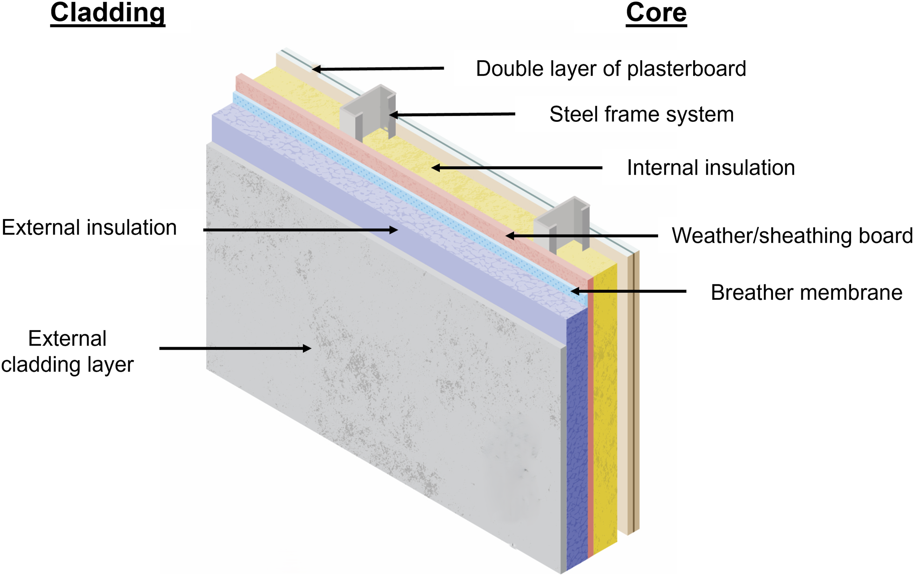
List of target materials, group, type, thickness, GWP and cost.
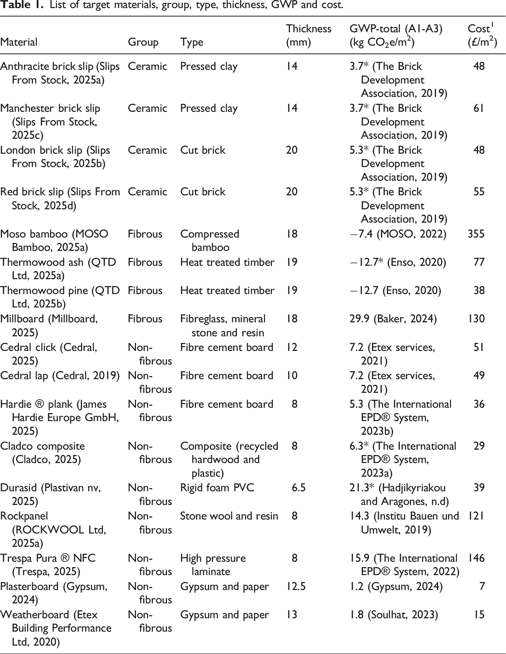
The materials were classified into three groups based on their morphology: ceramic materials produced from clay; a second group of fibrous materials characterised by long, thick, visible macro fibres; and a third group, termed non-fibrous materials which encompasses all remaining samples, including those which contain micro-fibres not visible to the naked eye. The type of material and thickness specified on material data sheets is also shown in Table 1.
Ceramics
Brick slips contain lower embodied carbon than full bricks as they are roughly 1/5 thickness of a standard brick and GWP for bricks is calculated by the one tonne (Institut Bauen und Umwelt e.V. (IBU), n.d). They can either be mechanically fixed to rails or adhered to external wall insulation or backer boards (Details Library, 2023), in this study all of the brick slips were designed to be adhered to a backing. London brick slip (Slips From Stock, 2025b) and Red brick slip (Slips From Stock, 2025d) have a nominal thickness of 20 mm, cut from real full bricks. Anthracite brick slips (Slips From Stock, 2025a) and Manchester brick slips (Slips From Stock, 2025c) have a nominal thickness of 14 mm, made from pressed clay with a smoother more tile like appearance. The cut bricks had more variance in dimensions (six samples differed in length by up to ±5 mm, ±3 mm in width and ±1 mm thickness). The variance is likely due to surface roughness and inaccuracies in the cutting and firing processes.
Fibrous materials
Four products contained long, thick, visible fibres either in the form of wood grain (Thermowood pine, Thermowood ash) or as a fibre composite (bamboo composite and Millboard). The Thermowood products and bamboo are biogenic (Collins, 2025) or bio-based materials that are produced from living organisms which can help drive down GWP (Mouton et al., 2023) due to their ability to sequester carbon (Boury, 2024). Two of the products are solid wood products which have been thermally treated to improve material properties and durability (Thermowood.com, n.d): Thermowood pine (softwood) (QTD Ltd, 2025b) and Thermowood ash (hardwood) (QTD Ltd, 2025a). The bamboo product is a composite made by impregnating bamboo fibres with phenolic resin before being heated and compressed into high density planks (MOSO Bamboo, 2025b). The bamboo and timber products all have fibres aligned parallel to the length which are clearly visible from all sides. Millboard (Millboard, 2025) is a long fibre composite made from fibreglass fibres, limestone and polyurethane with a Lastane (a thermoplastic polyurethane) surface layer (The Millboard Company Ltd, 2024). The surface layer which is up to 2 mm thick is laid in a mould and then filled with the fibre reinforced resin-mineral filler. It forms a foamed cement-like matrix which contains fibres that were observed after breaking measuring up to 1 mm thickness and 30 mm in length that are randomly orientated in the matrix (Baker, 2024).
Non-fibrous materials
The final category of products was classed as non-fibrous containing the products where no large fibres were visible without magnification and were also not ceramic. The products in this category represent a range of material types, manufacturing processes or differences between brands. Three types of fibre cement board (Designing Buildings Ltd, 2025) of varying thicknesses were chosen from two different manufacturers. Cedral click (Cedral, 2025) cladding is designed to slot together and is 12 mm thick (±1 mm) (Cedral, 2020). Cedral lap is a 10 mm (±1 mm) version from the same manufacturer (Cedral, 2019), designed to be overlapped. Hardie plank (James Hardie Europe GmbH, 2025) is a different brand which is only 8 mm thick (−0.8 mm/+1.2 mm) (James Hardie Building Products Ltd, 2019) and is also designed to be lapped. Fibre cement boards are manufactured by mixing cement, sand and a cellulose pulp made from recycled wood products with additives before being pressed into sheets, autoclaved and cut into planks (NBP Ltd, n.d). No large fibres are visible externally, but when a board is broken, microscopic fibres (<1 mm) were visible using a magnifying glass. The fibres are slightly aligned through longitudinal pressing of the sheets by a roller, and the boards are reported as anisotropic with different properties perpendicular and parallel listed in the data sheet (Cedral, 2019). The fibre cement board materials were kept in the non-fibrous category, but there is scope to add a sub-set of ‘micro-fibres’ if greater fidelity of grouping is required.
Two of the products are large panels which represent stone, tiles or other sheet materials. Rockpanel (Rockwool Ltd, 2025a) is made from crushed rock (basalt or dolomite) and recycled mineral wool fibres which are mixed and heated to 1500°C (Rockwool Ltd, 2025b). It is pressed with a thermosetting resin before colour coating, making it isotropic. Trespa (Trespa, 2025) is also made using a thermosetting resin by impregnating natural wood fibres before being bonded using heat and high pressure to form a high-pressure laminate (HPL). Cladco composite (Cladco, 2025) is a mix of 60% recycled hardwood and 40% recycled plastic. The fibres are shredded and mixed with additives and colourant before being heated and extruded into shape. The extrusion process is likely to change the strength along each axis. Durasid (Plastivan nv, 2025) is polymer made from a rigid polyvinyl chloride (PVC) foam core with a topcoat that is co-extruded with the core.
Plasterboard (Gypsum, 2024) and weatherboard (Etex Building Performance Ltd, 2020) are gypsum-based materials that are typically used as internal lining layers or a sheathing board within the core rather than an external cladding material. They are made from gypsum plaster sandwiched between two layers of paper to create a rigid board (Knauf Group, 2025). They have been included in testing assess whether the internal layers would provide additional impact protection and to compare performance with the external layers.
An overview of the material composition and the manufacturing processes is shown graphically in Figure 2. The graphic shows the three main groupings: ceramic, fibrous and non-fibrous (under-lined with dashed lines) along with sub-groups of: pressed clay, cut clay bricks, composites, natural fibres, recycled wood fibres, wood, polymer, rock/mineral and also matrix types of cement and thermoset resins. Illustration of material composition groups: ceramics, fibrous and non-fibrous (under-lined with dashed lines) along with sub-groups and manufacturing processes.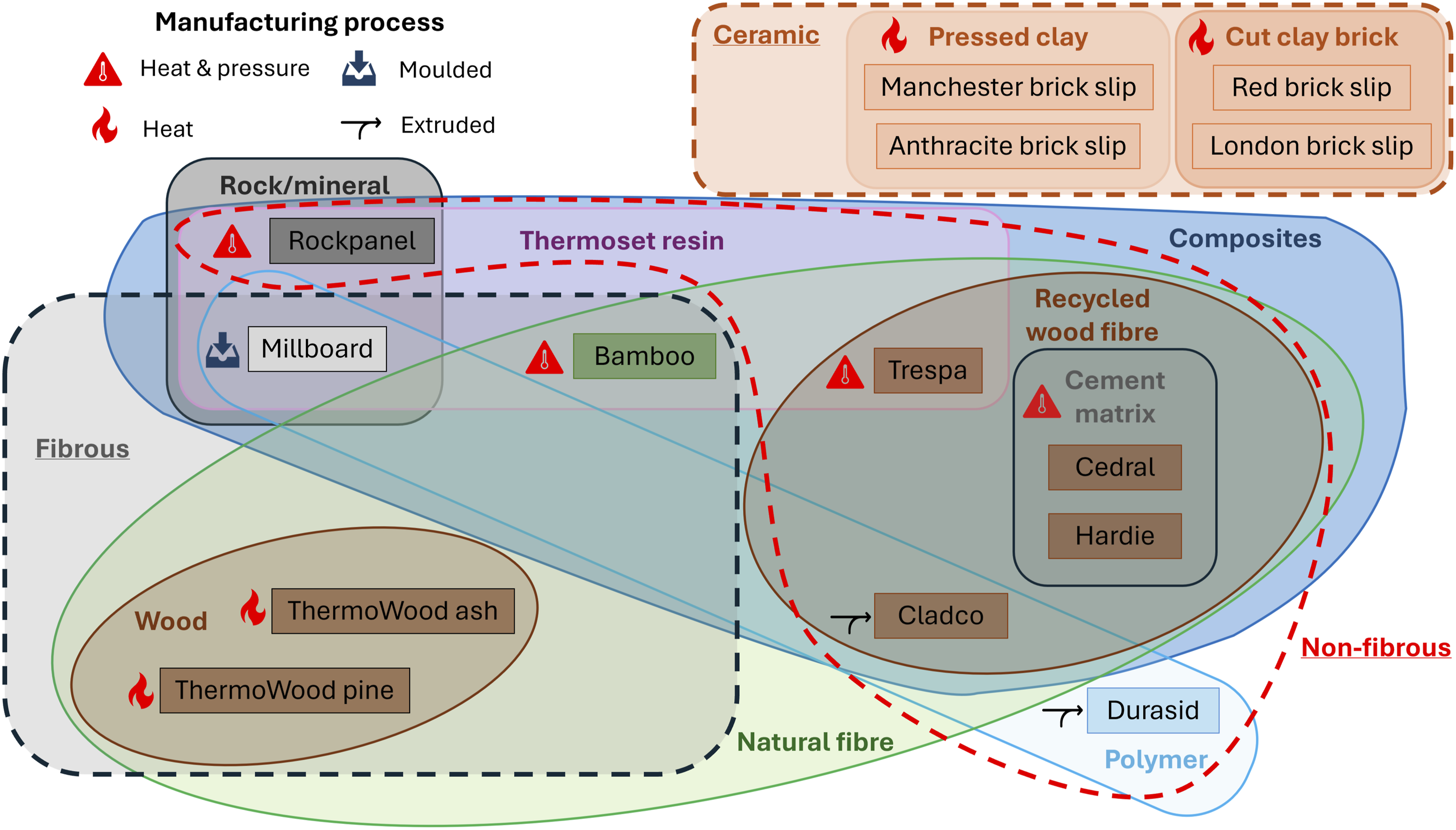
Projectile materials
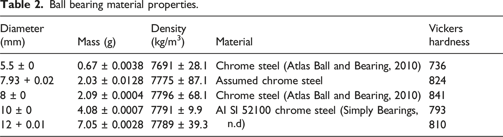
Ball bearing material properties.
Methods
Fragment penetration test
A light gas gun was used to replicate blast driven ball bearings in a controllable manner, as shown by Read et al. (2023, 2025). The setup used the Explosive Low Velocity Impact System (ELVIS) gas gun at Shrivenham and is shown graphically in Figure 3. The velocity of the ball bearing was measured by infrared light gates spaced 40 mm apart in the barrel, with the results taken from a Tektronix oscilloscope. The high-speed camera used was a Phantom V1212 operating at 30,000 fps, a resolution of 896 × 352 pix and 5 microsec exposure which was used to calculate impact and residual velocities using the Phantom Control Camera (PCC) application (version 3.9, software available online (Vision Research Inc., 2025)). The target was observed through the target chamber viewing point with a backlight within the chamber to illuminate the rear face. ELVIS gas gun and instrumentation illustration.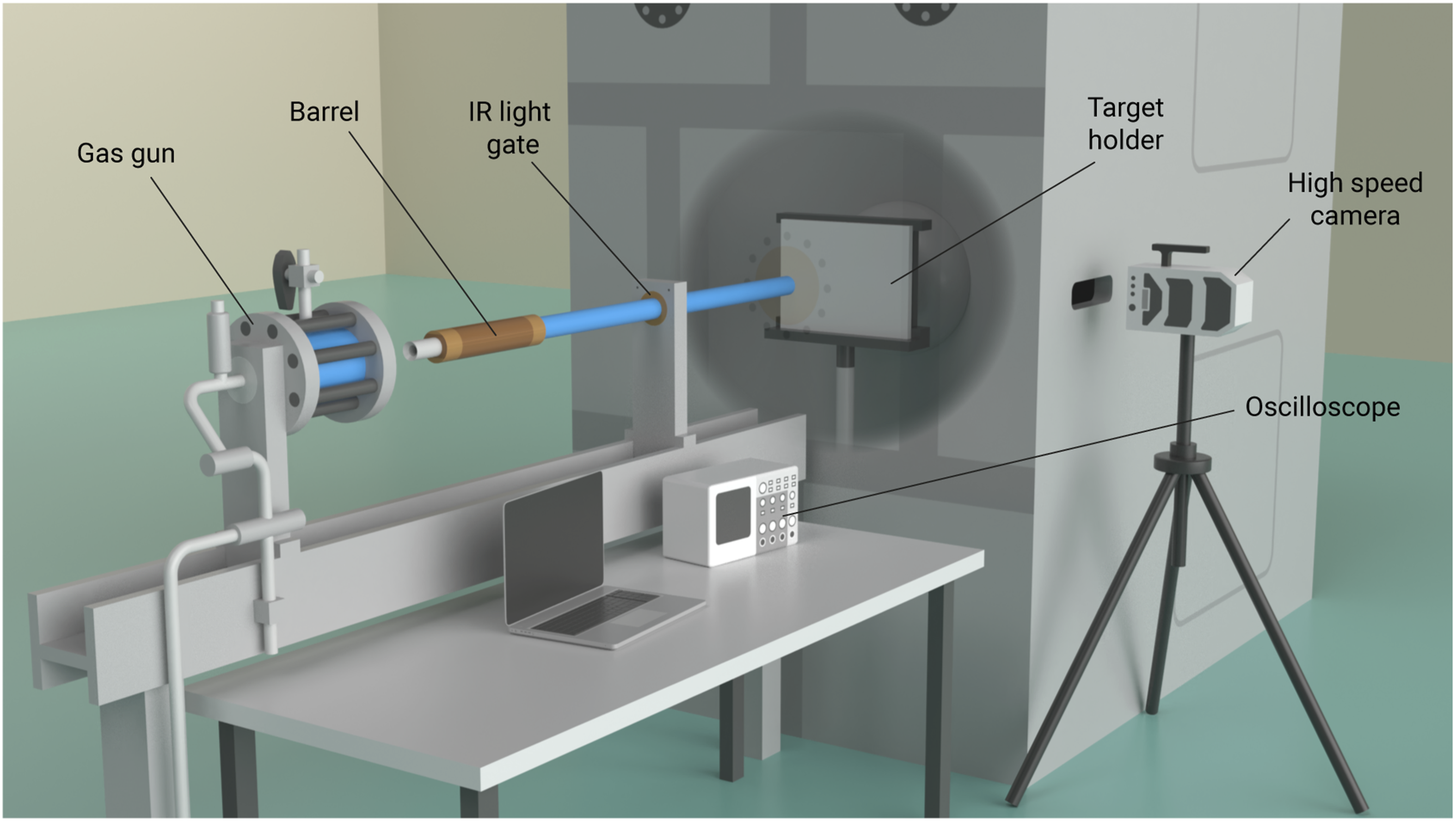
Targets were cut to a maximum of 150 mm long (horizontal measurement) by 150 mm wide (vertical measurement) for sheet products. For products in plank form, the width varied depending on the profile, but length was cut to 150 mm. The brick slips, Rockpanel and Trespa were set sample sizes with the minimum width being on average 63 mm for the brick slips. Prior to testing, target length and width was recorded with a metal rule to the nearest millimetre and thickness was measured in the centre of the side with digital vernier callipers to the nearest 0.01 mm. Variance of thickness was greatest for the cut clay bricks and Millboard with values of up to ±1.5 mm due to uneven surfaces. The remainder of the targets saw thickness vary from +0.4 mm to −0.3 mm from the average target thickness of each material. All targets were placed on a target holder plinth with a square frame. The targets were placed vertically spanning between the frame horizontals and were secured to the top of the frame using a G-clamp.
Following impact, the sample was removed from the gas gun and categorised as NP = no penetration (ricochet); PP = partial penetration (embedment) and CP = complete penetration (perforation) as per definitions described by Backman and Goldsmith (1978) and visually indicated in Figure 4. For the brittle ceramics, a PP was recorded if the target was destroyed but the ball bearing did not pass the rear of the target. Ballistic limit definitions: no, partial and complete penetration (NP, PP, CP).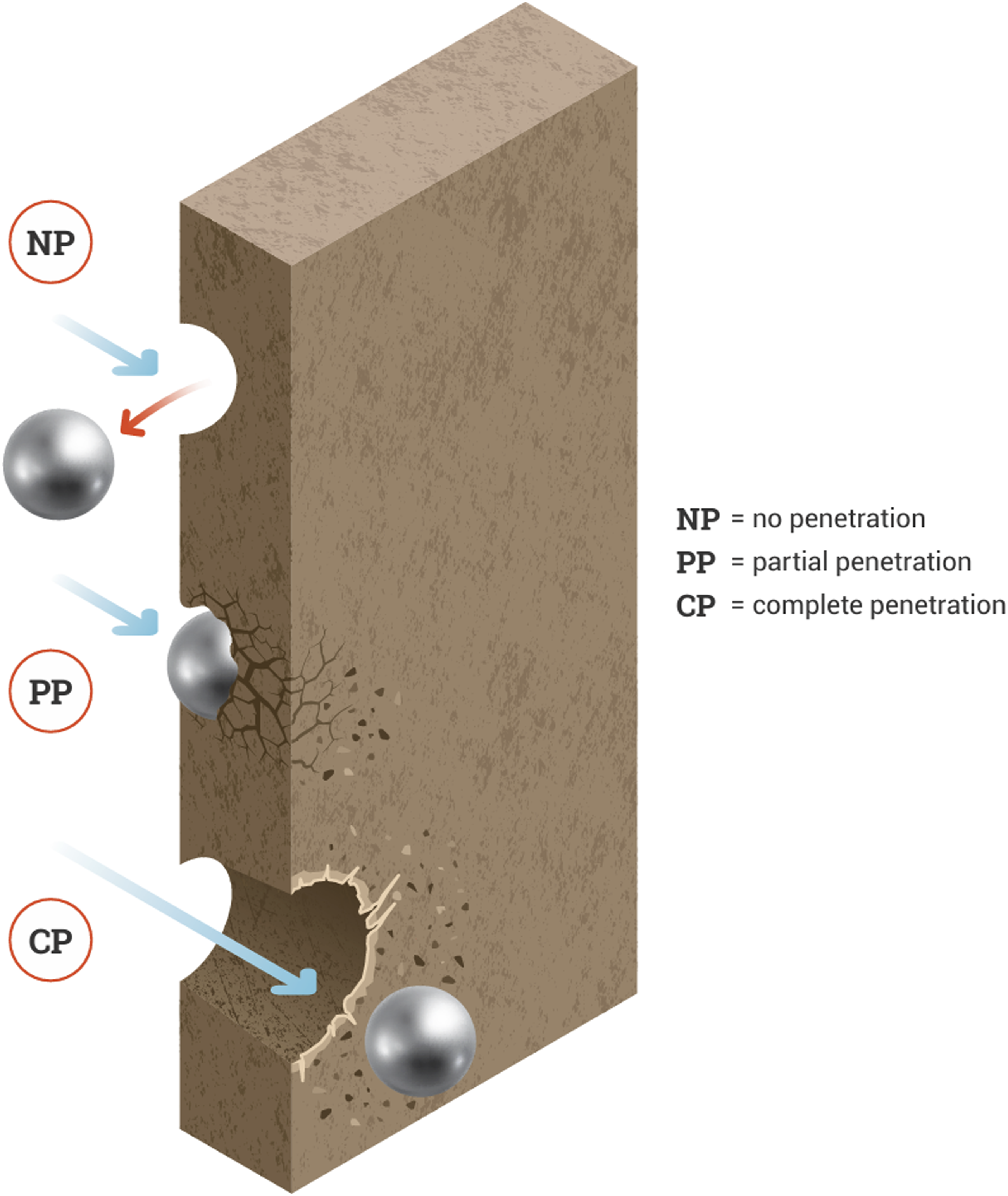
The post-test weight of the target was recorded; failure photographs and damage measurements were also logged. The failure modes for the CPs of each material were recorded using descriptions adapted from Rosenberg and Dekel (2016) as shown in Figure 5. Impact failure mode illustrations.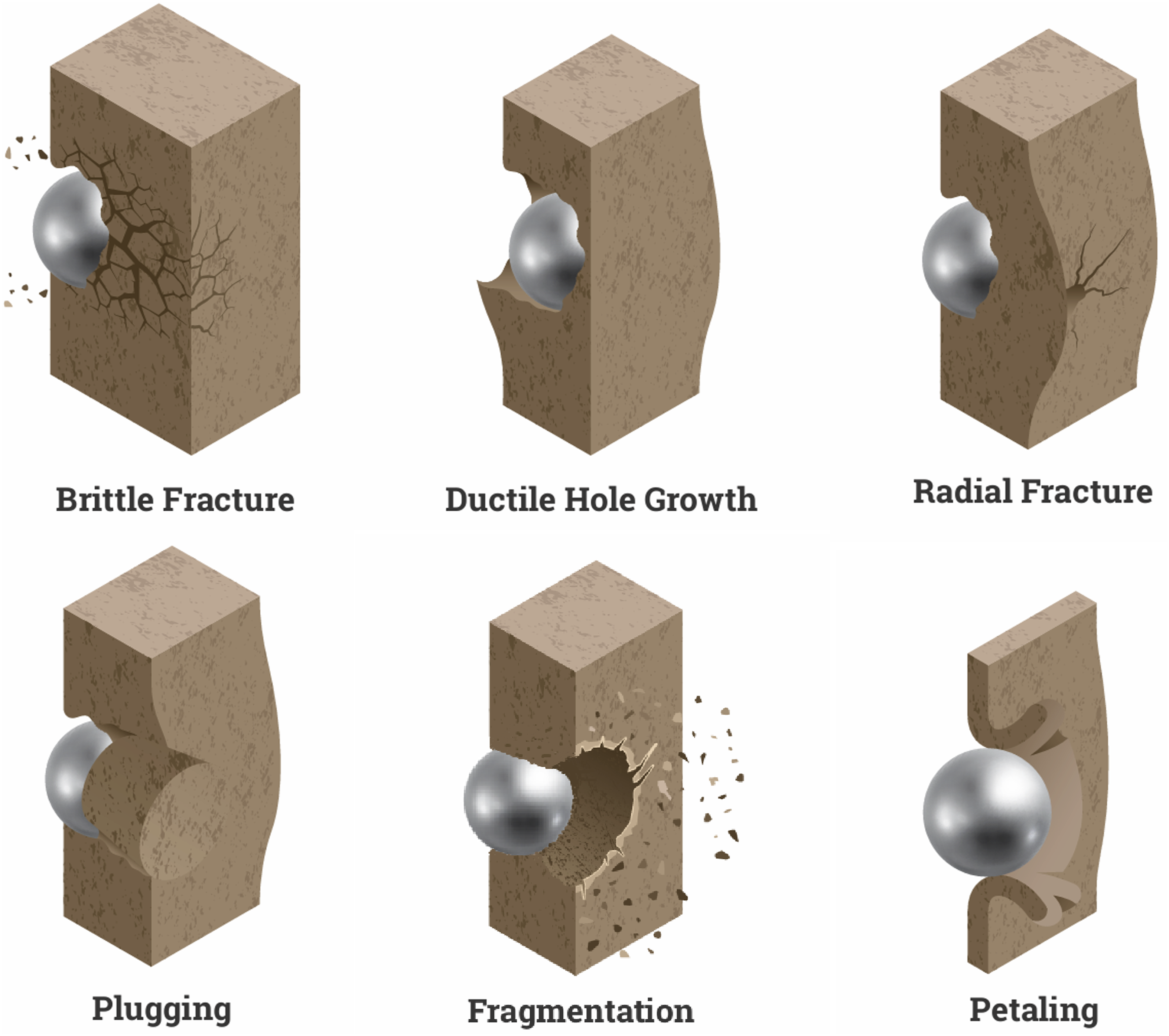
V50 ballistic limit calculations
To compare the performance of the targets, the V50 ballistic limit is a common ballistic characterisation, and it is defined as the velocity at which the particular projectile has a 50% probability of perforating the target (Johnson et al., 2014). The V50 was initially calculated using “3 and 3” stopping criteria (33SC) and arithmetic mean estimator (AME) which is the average of the three highest velocity non-penetrations (NP or PP) with the three lowest velocity perforations (CP) (Johnson et al., 2014). The impact velocities used in the calculations were taken from the high-speed camera footage. A second method was also used called the Probit Maximum Likelihood Estimator (Probit MLE) as described by Johnson et al. (2014). This was calculated using the Minitab software Reliability/Survival Probit Analysis tool (Minitab, 2024).
Results and discussion
V50 ballistic limit results
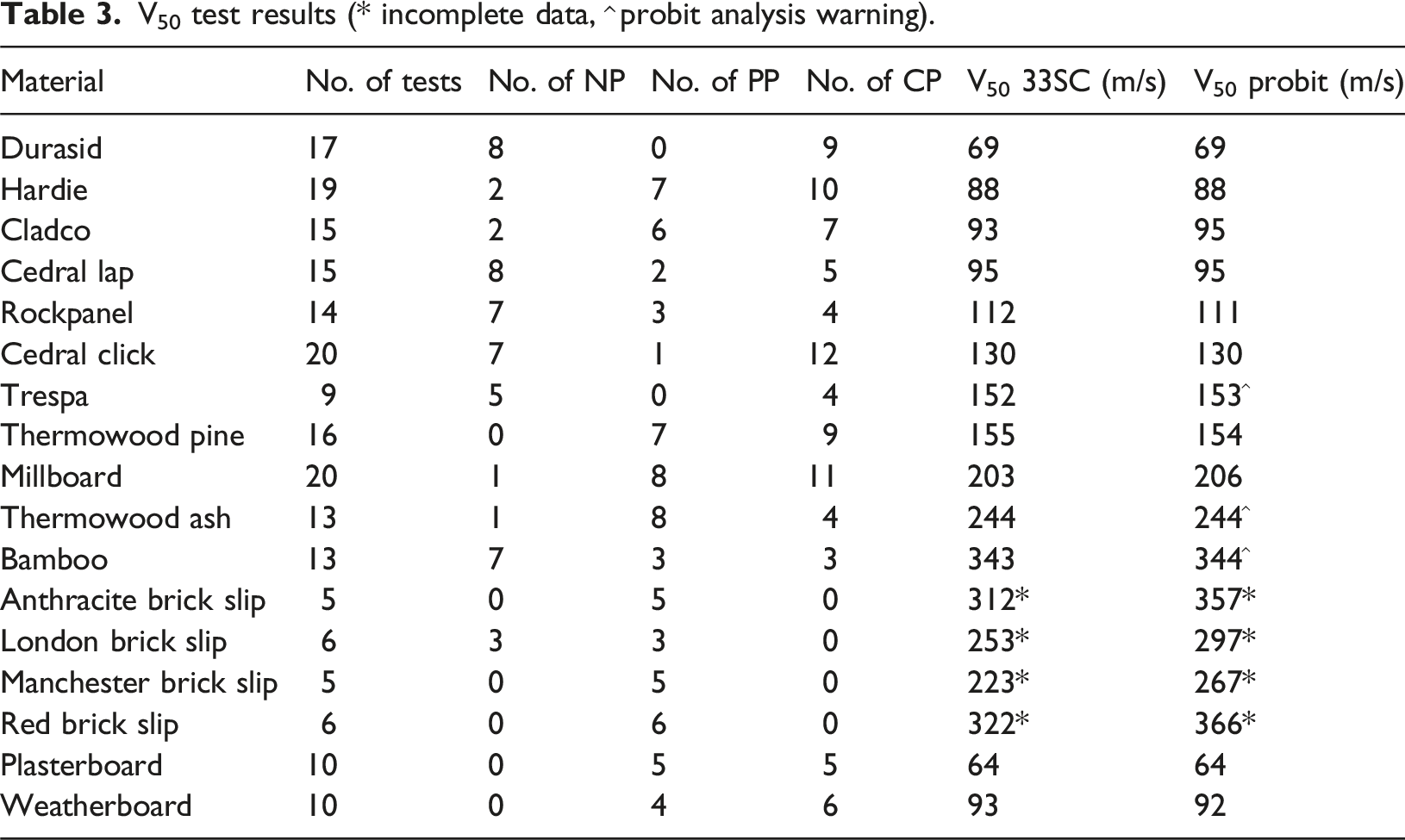
V50 test results (* incomplete data, ^ probit analysis warning).
Failure mechanisms
Front face damage
For the majority of targets, the front face damage was a circular hole with a diameter up to the ball bearing size. Evidence of radial cracking around the hole was seen with the Durasid targets, and the two thermowood products had cracking and splitting along the grain originating from the penetration. The hole at the front of the Millboard targets closed up behind the ball bearing to between 3 and 6 mm in diameter even on complete penetration. The bamboo targets were the only ones to produce front face fragmentation.
For most non-penetrations, spherical indentations were observed caused by local compression of the front face. For most partial penetrations, the ball bearing could be seen protruding from the rear face with the exception of Millboard and the Thermowoods where the ball bearing could be completely embedded without being visible. The ceramic brick slips all suffered from brittle radial failures with the cut brick slips (London and Red) having a larger front face hole (7 mm diameter) than the pressed clay tiles (Anthracite and Manchester) which typically cracked in half with only an indentation. The failure pictures of targets which were completely penetrated are shown by group in Figure 6. Front face failure pictures split into fibrous, non-fibrous and ceramic groups.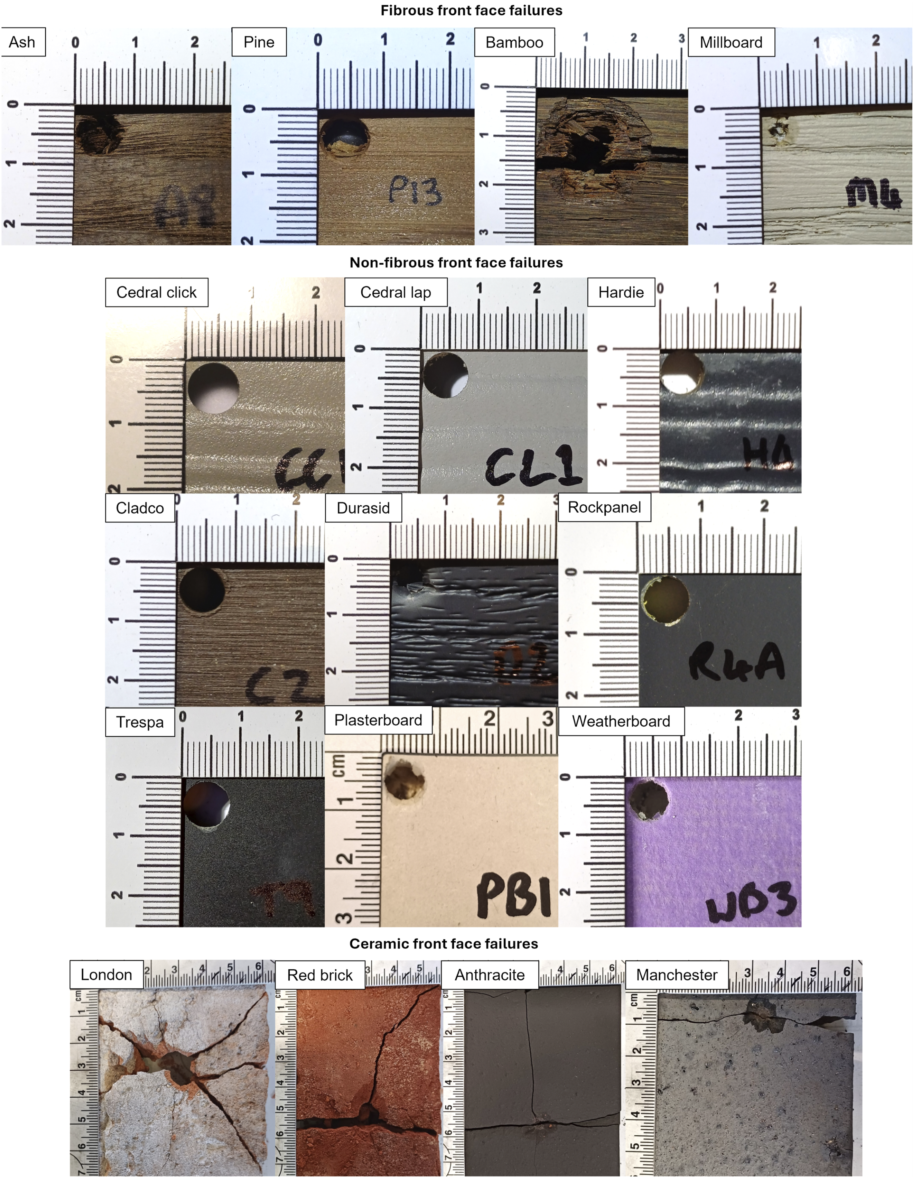
Rear face damage
The rear face damage varied between target types and often showed more than one of the failure mechanisms described in Figure 5. The fibrous products all showed a combination of petaling and fragmentation of fibres. This is most apparent with the Millboard targets where the rear fibres petaled outwards and the matrix fragmented, shown in the bottom left of Figure 7. The natural fibre products showed a form of petaling along the grain of the fibres, this could be classed as splitting, however, that terminology was not found in ballistic failure literature. Figure 7 shows CP failures for the fibrous products which were consistent for all CPs. Petaling and fragmentation failure of the fibrous targets.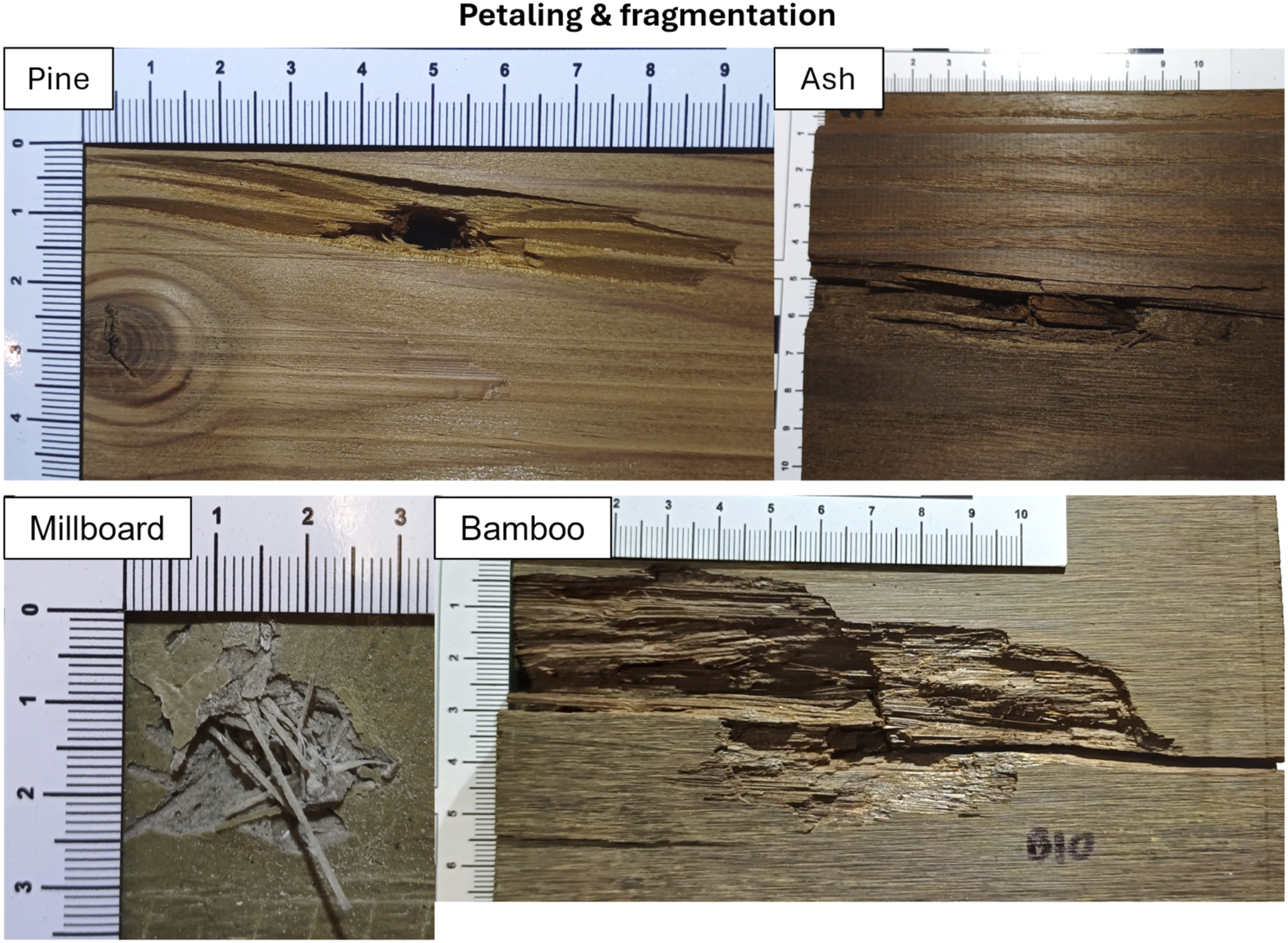
The most common failure mode was a combination of fragmentation and plugging, where small conical plugs with a spherical indentation were found on the floor of the target chamber. This mechanism was seen for all fibre cement board products and the Cladco composite. All plugs were conical in shape with a spherical indentation at the contact face and wider base. Plug weights were in the range of 0.6 to 0.7 g for full thickness plugs. For fibre cement board (Cedral click, Cedral lap and Hardie) PPs the failure can be seen as radial cracking which caused rear face petaling before the projection of the central plug, as shown in the centre of Figure 8. For CPs, this left a conical shaped crater as shown in the other pictures in Figure 8. Typical fragmentation and plugging failures of Cedral lap, Cedral click, Cladco and Hardie targets.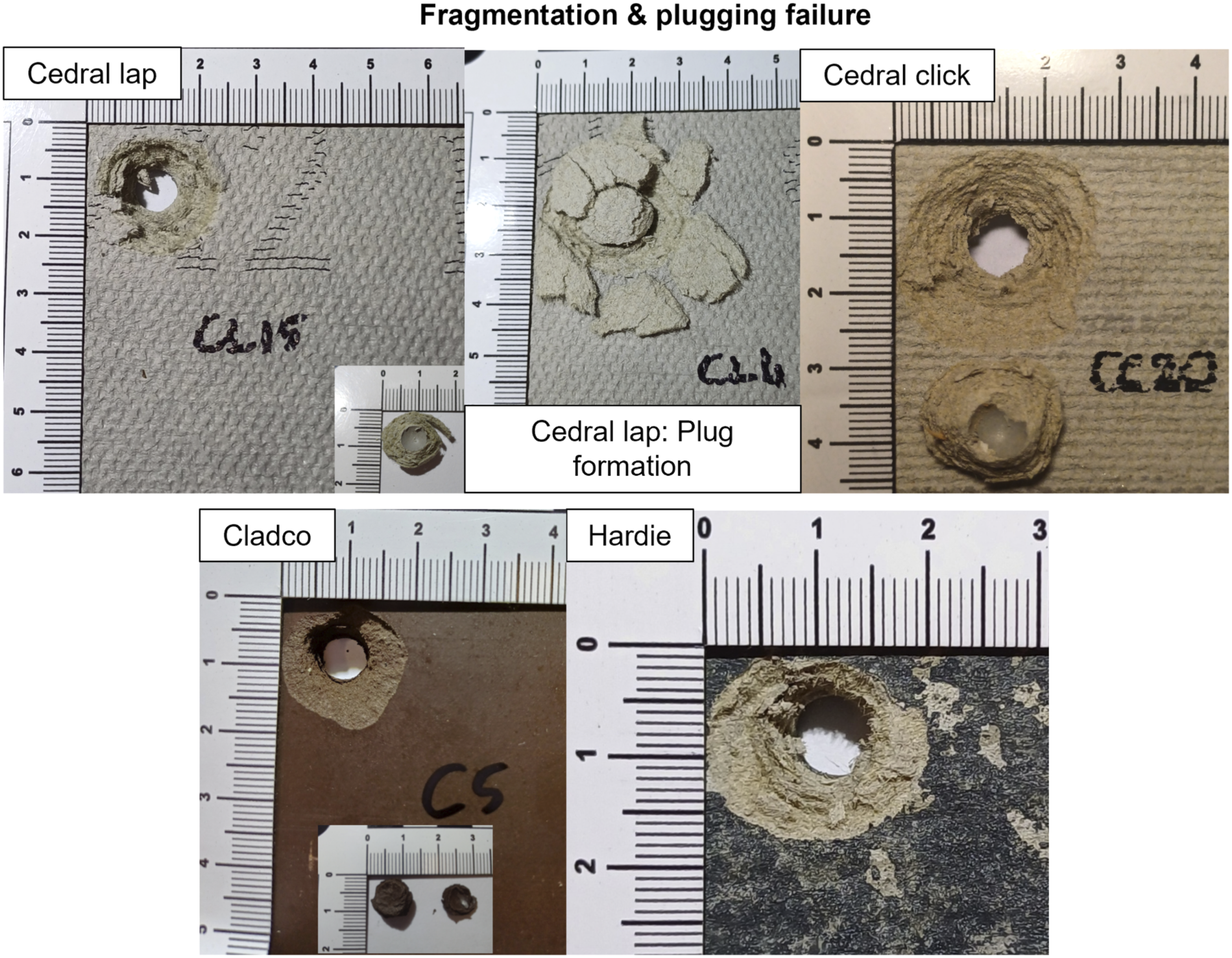
The ceramic products all suffered from brittle, radial failures. The cut bricks (London and Red) cracked into 5 or 6 pieces and rear face craters formed as fragments were projected from the back. The pressed clay tiles (Anthracite and Manchester) typically cracked in half producing fewer fragments as shown in Figure 9. Failure mechanisms for ceramic brick slip products.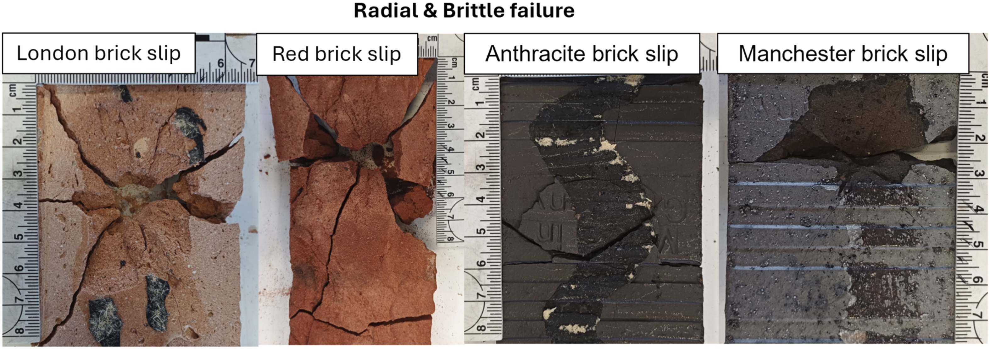
The thinner products of Durasid and Trespa both demonstrated radial cracking with rear face fragmentation and full width cracking in the case of Durasid. The Trespa showed the formation of central fragments which could potentially be the formation of a plug, shown on the right of Figure 10 on a target that was only partially penetrated. Rockpanel showed fragmentation failure leaving a small conical crater. Petaling was seen with the plasterboard and weatherboard where the rear paper was torn and peeled back, sometimes leaving a cone of gypsum on the paper. Other failure mechanisms observed: radial, fragmentation and petaling.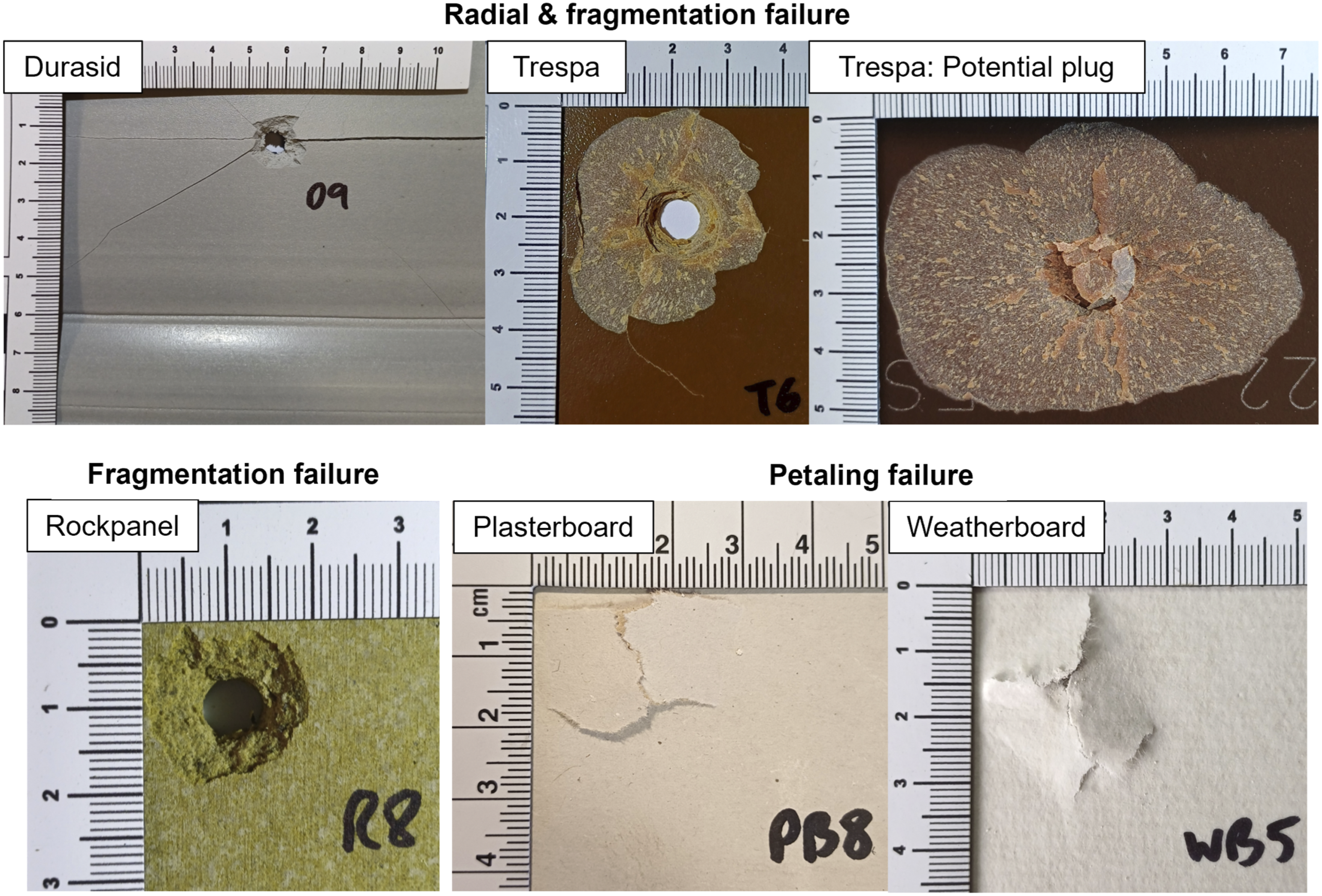
Summary of failure mechanisms by material grouping.
Target thickness effects
In ballistics, targets can be classified by thickness as: semi-infinite, intermediate or thin (Rosenberg and Dekel, 2016). Semi-infinite requires there to be no lateral or rear face influence on the penetration process but since all targets suffered rear face damage, none of them can be classified as semi-infinite (Rosenberg and Dekel, 2016). Intermediate targets are described as having rear face damage and the rear surface exerts influence during the majority of the penetrator motion (Backman and Goldsmith, 1978). Thin targets do not have stress and deformation gradients throughout the thickness and are perforated by the projectile but can induce damage to it (Rosenberg and Dekel, 2016). Backman and Goldsmith (1978) also defined ‘thick’ targets that are influenced by the distal boundary, but only after substantial travel into the target. Using the above definitions, the cladding targets tested fell within the intermediate target range description with rear face influence during most of the penetrator motion. It is noted that ballistic target thickness classification can be established by stress wave rates as described by Backman and Goldsmith (1978) but this was out of scope for this study.
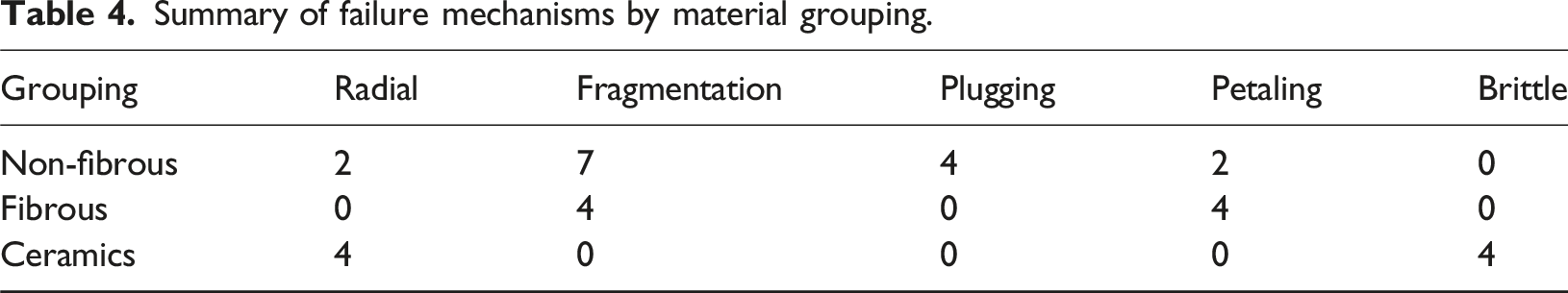
A linear regression model was produced for Probit V50 against target thickness to identify if this simple property could be used to predict the V50. A positive linear fit yields an R2 of 50% as shown in Figure 11, but there are some significant outliers, typically from the ceramic and fibrous groups. The brick slips are outliers on the thickness versus V50 as the V50 values are underestimates due to the lack of CPs achieved. These ceramics also failed radially due to low tensile strength compared to compressive strength (Backman and Goldsmith, 1978; Chiquito et al., 2021). The non-fibrous targets that failed by plugging (Cedral click, Cedral lap, Hardie and Cladco) suggest a relationship with shear strength as material shears around the slug (Backman and Goldsmith, 1978). V50 increased with thickness for the three fibre cement board products (Cedral click, Cedral lap and Hardie) supporting the shear failure theory as more material would provide increased resistance. Linear regression model for V50 against thickness.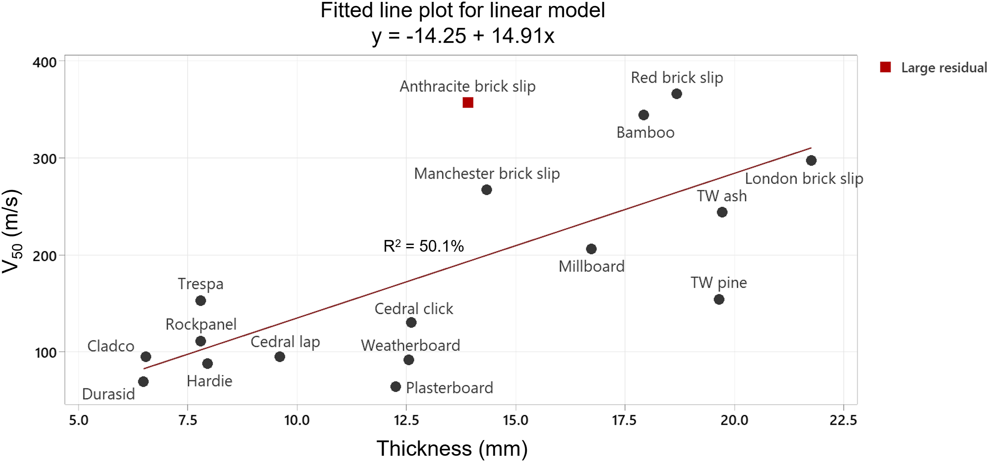
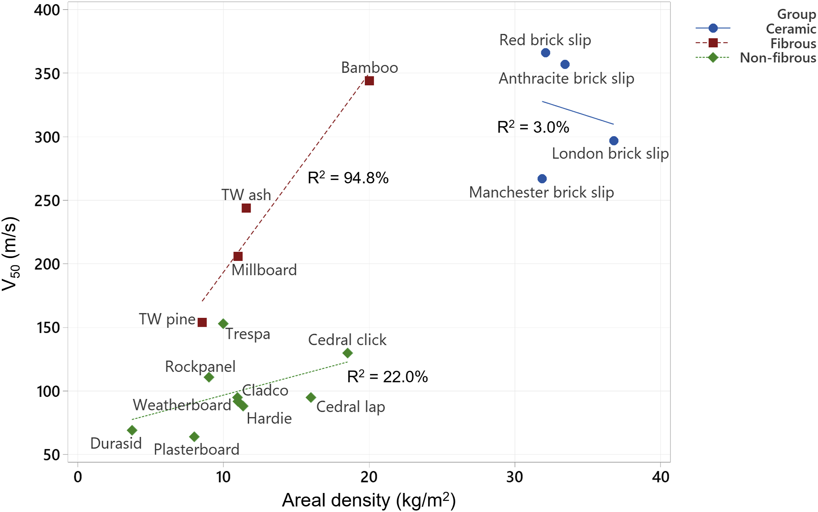
The property of areal density can also be used to compare the resistance of target materials, it is calculated by multiplying the target density by thickness (Ballistic Analysis Laboratory, 1961; Smith and Hetherington, 1994). Figure 12 shows V50 versus areal density with groupings overlayed showing three significant clusters. There is a general linear relationship with an R2 of 65% for all materials but when groupings are applied a stronger linear relationship is apparent for the fibrous group. This is shown in Figure 13 where the line of best fit for the fibrous group returns an R2 of 94.8%. This supports the work by Weaver et al. (2020) who also documented a linear relationship with the testing of cross laminated timber when comparing it to other materials. Linear regression model for V50 against areal density. Scatterplot of V50 versus areal density with lines of best fit for material groupings.
Target penetration depths
An observation was made with respect to the variance in penetration depth or ratio of penetration (P) into the thickness (T) of the target (P/T). Each target showed a maximum penetration thickness and if this was exceeded, then a CP occurred. This concept is shown in Figures 14 and 15 where P/T is plotted against initial velocity for each material. The blue marks show NP or PPs, where the ball bearings either left an indentation or were embedded in the target. The red marks are CPs where the ball bearing exited the rear face of the target, and the V50 is shown by a dashed red line. Where the linear regression line meets the V50 line, the value of P/T is shown. If the P/T value is greater than 1, then the ball bearing is still embedded but is protruding from the rear of the target. The value of P/T at the V50 can be described as the perforation limit (National Defence Research Committee, 1946). P/T versus initial velocity for combined petaling, fragmentation & plugging failures with PP shown in blue and CP shown in red. P/T versus initial velocity for other failure mechanisms with PP shown in blue and CP shown in red.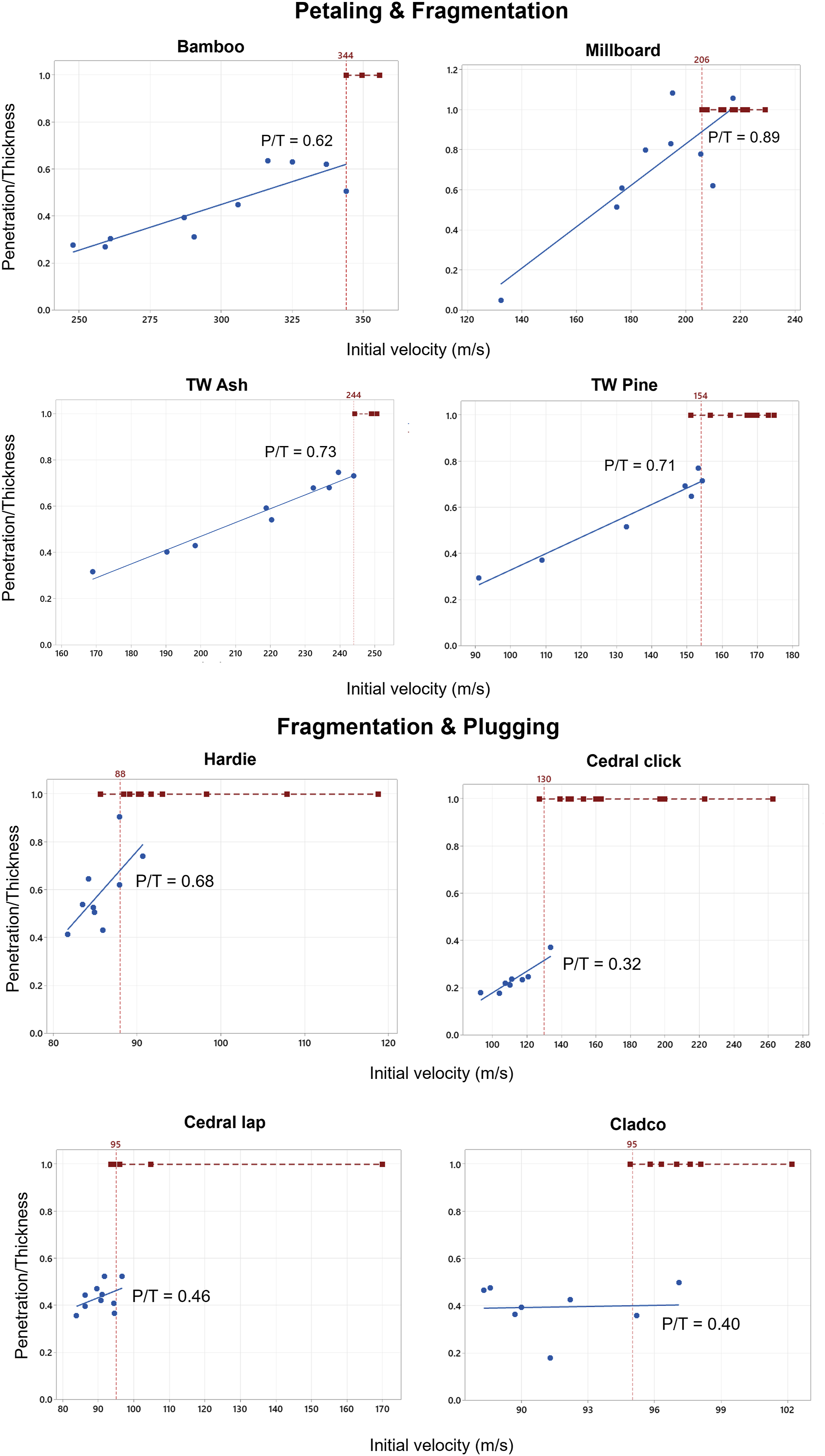
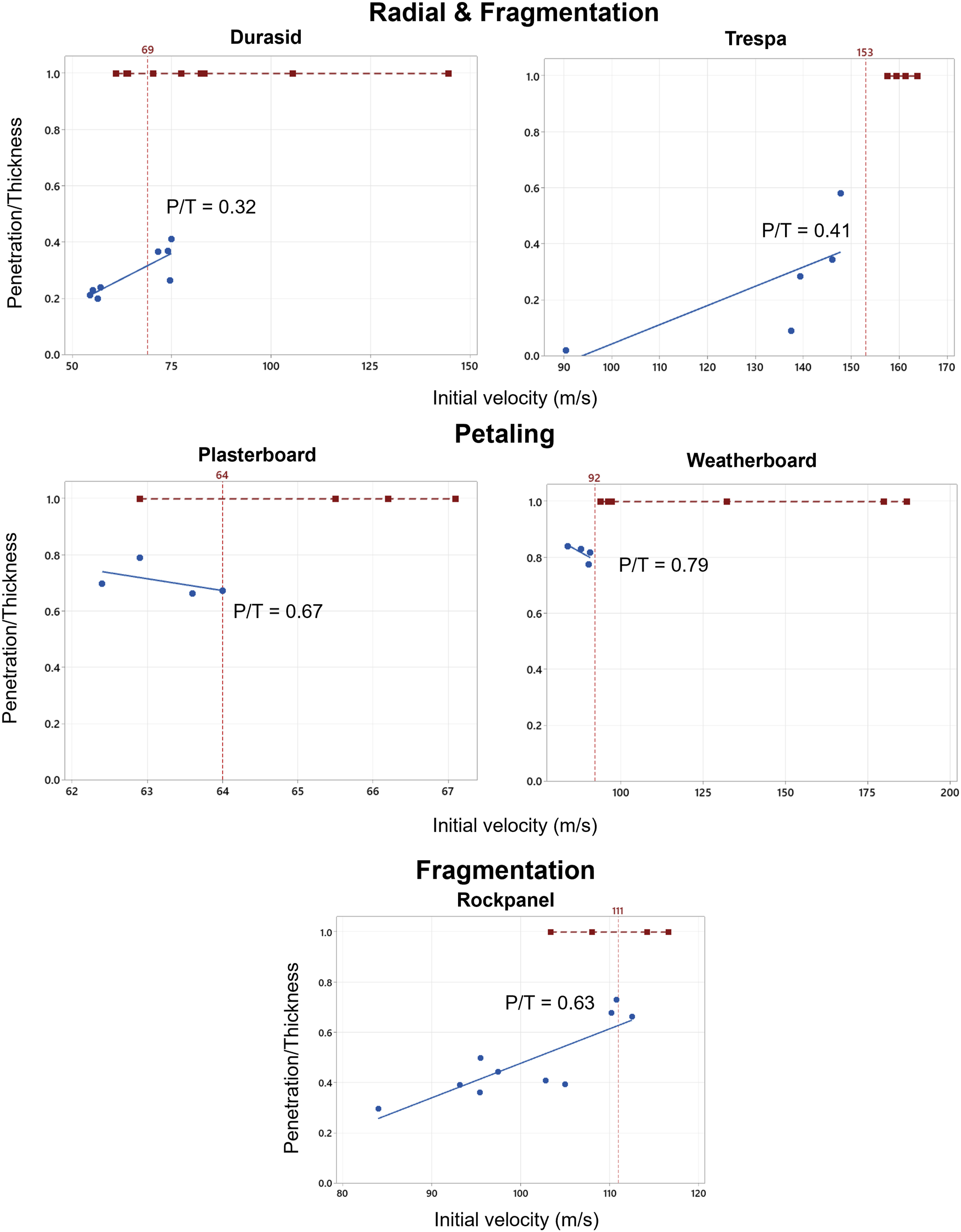
The values of P/T at the perforation limit range from 0.32 for Durasid and Cedral click to 0.89 for Millboard. Typically, if the projectile travels more than the P/T limit found for each material, then it will continue through the full thickness and result in a complete penetration. The two Thermowood products had a similar P/T of 0.73 for the ash and 0.71 for the pine. The more brittle and thin products of Durasid and Trespa were both quite low at 0.32 and 0.41 respectively. Since the fibre cement board products showed increased penetration resistance with thickness, it was expected that the P/T for these products would be similar since a certain proportion would need to shear before the plug is formed and released. However, they ranged from 0.32 for Cedral click (the thickest at 12 mm) to 0.68 for Hardie (the thinnest at 8 mm) suggesting a more complex relationship involving the thickness, density and the calibre of the ball bearing. The fibrous and gypsum products tended to have the highest P/T intercept due to their ability to absorb the ball bearing between the fibres or paper and maintain embedment compared to other materials.
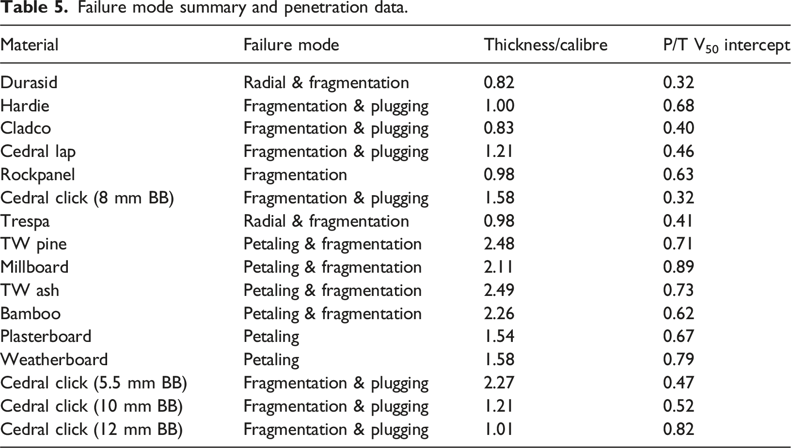
Failure mode summary and penetration data.
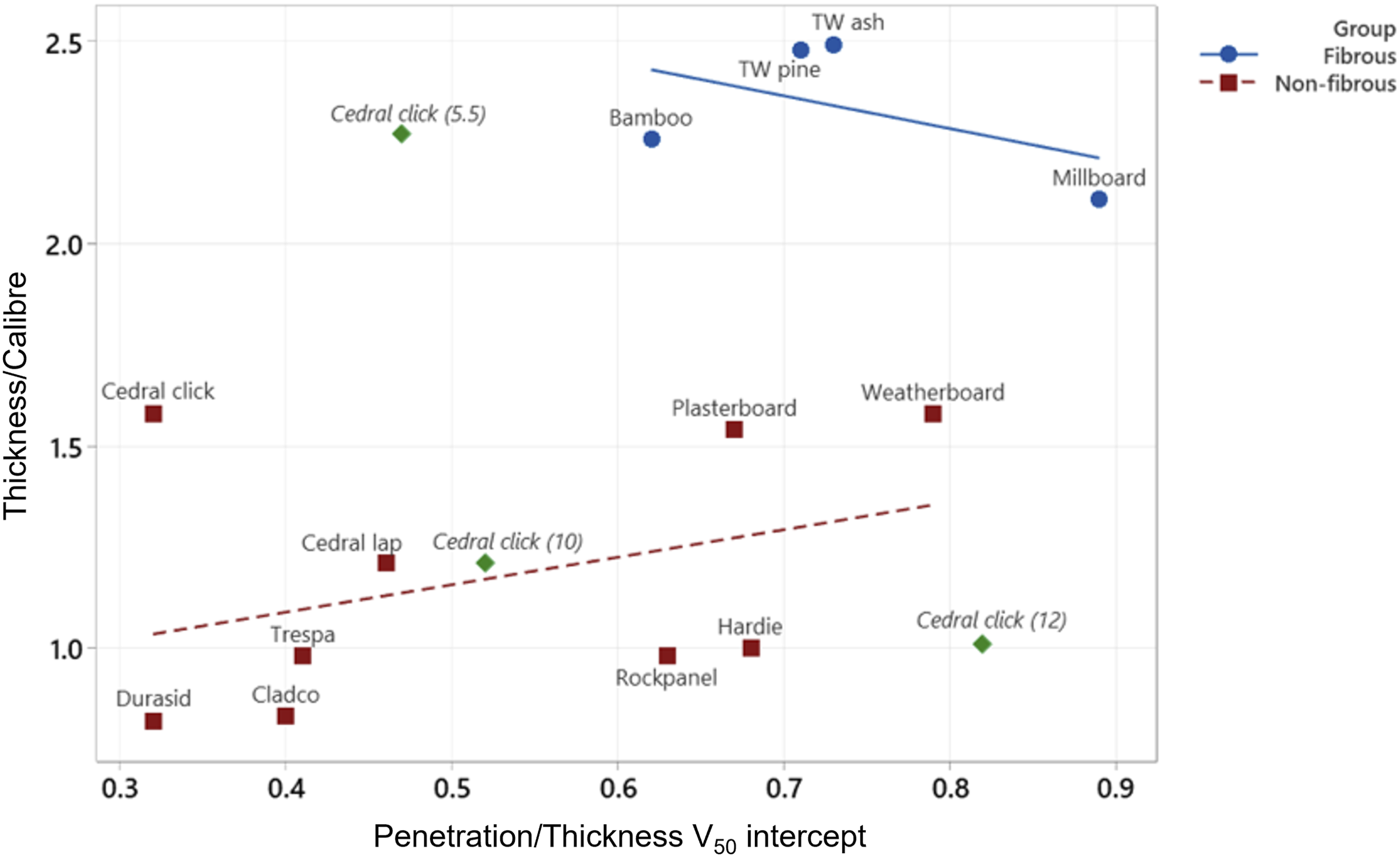
Target thickness/BB calibre against P/T V50 intercept in groupings with additional Cedral click ball bearing sizes added (in green, BB diameter in brackets).
The P/T intercept also changes if the ball bearing size is increased, as shown with the green icons for Cedral click in Figure 16. There is no obvious pattern to the distribution, so ball bearing size effects are discussed in more detail.
Ball bearing size effects
Test data for multiple ball bearing sizes against Cedral click.
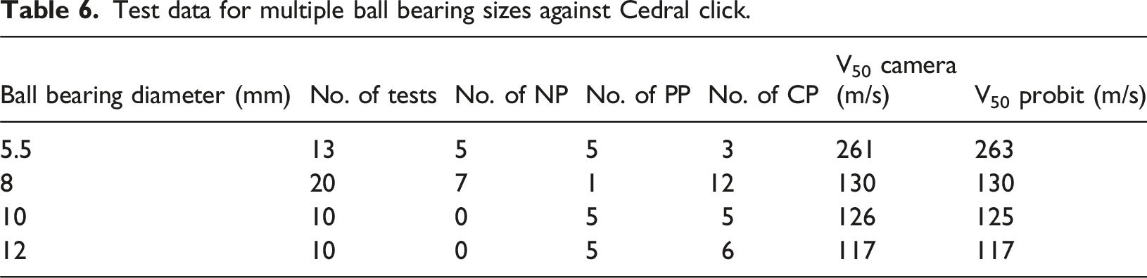
The failure mechanism did not change with ball bearing size and fragmentation with plugging failures were still observed. There were more partial penetrations with the 10 mm and 12 mm ball bearings becoming embedded, and some horizontal full width cracks were seen with the 12 mm ball bearings. The average rear face crater sizes increased slightly from 26 mm for the 5.5 mm ball bearing to 29 mm for the 12 mm ball bearing. Some of the additional ball bearing size failures are shown in Figure 17 with the rear of a CP on the left, front of a PP in the centre and rear of a PP on the right. Cedral click failures using different ball bearing sizes (CP on left, PP centre and rear of PP on right).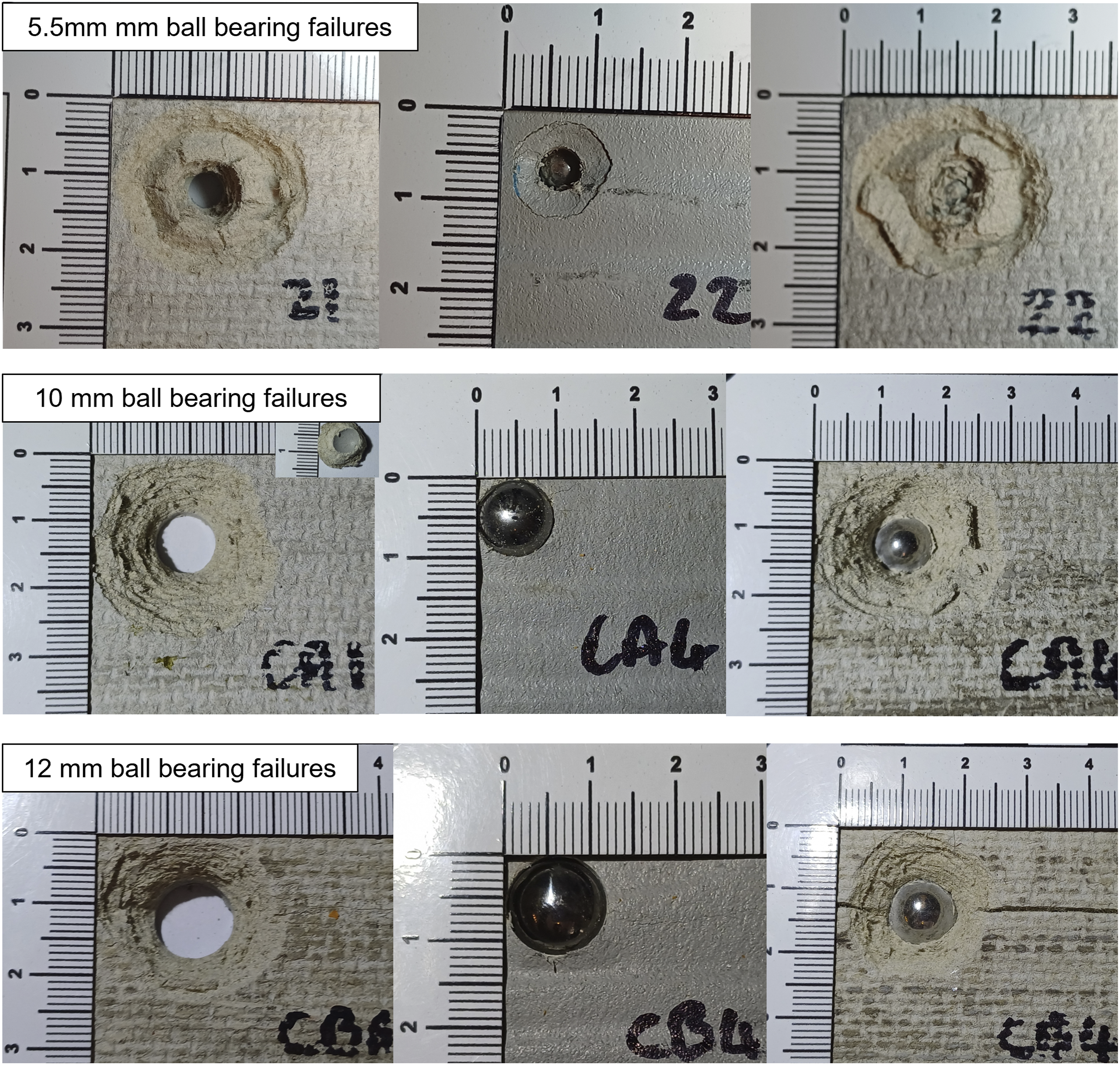
To assess the effect of ball bearing size on V50, the V50 data was plotted against thickness/calibre (T/D), and a non-linear regression analysis was performed to establish a line of best fit. A number of convex non-linear regression equations were tested, and the following exponential equation and parameters provided the line of best fit:
The graph in Figure 18 shows the gradual plateauing of the curve suggesting that ball bearings over 8 mm diameter are nearing the lowest V50. All of the V50 results are lower than the predicted velocities of blast driven ball bearings from explosive charges reported in literature. These velocities ranged from 200 m/s to 800 m/s (Kang and Chung Kim Yuen, 2020; Langdon et al., 2022; Qi et al., 2020) suggesting that blast driven ball bearings will easily the perforate exterior cladding tested in this study. Whilst the 10 mm and 12 mm ball bearings had slightly lower V50 limits, their greater mass would require a larger explosive charge to drive them at this velocity and less fragments could be fitted into a device. The 8 mm ball bearing is also comparable to the F6 fragment simulating projectile (FSP) with diameter of 7.49 mm ± 0.02 and mass of 2.79 g ± 0.02) (Barbillon et al., 2021). FSPs are used for classifying armour for protection against bullet and fragmentation threat (NATO Standardization Office, 2016a). Since terrorist actors are more likely to use easily obtainable fragmentation, an 8 mm ball bearing is potentially an optimum size to represent a worst case of blast driven fragmentation causing multiple perforations of the building cladding and potentially harming people inside. Non-linear regression of V50 versus T/C for Cedral click with ball bearing diameters (mm) in brackets.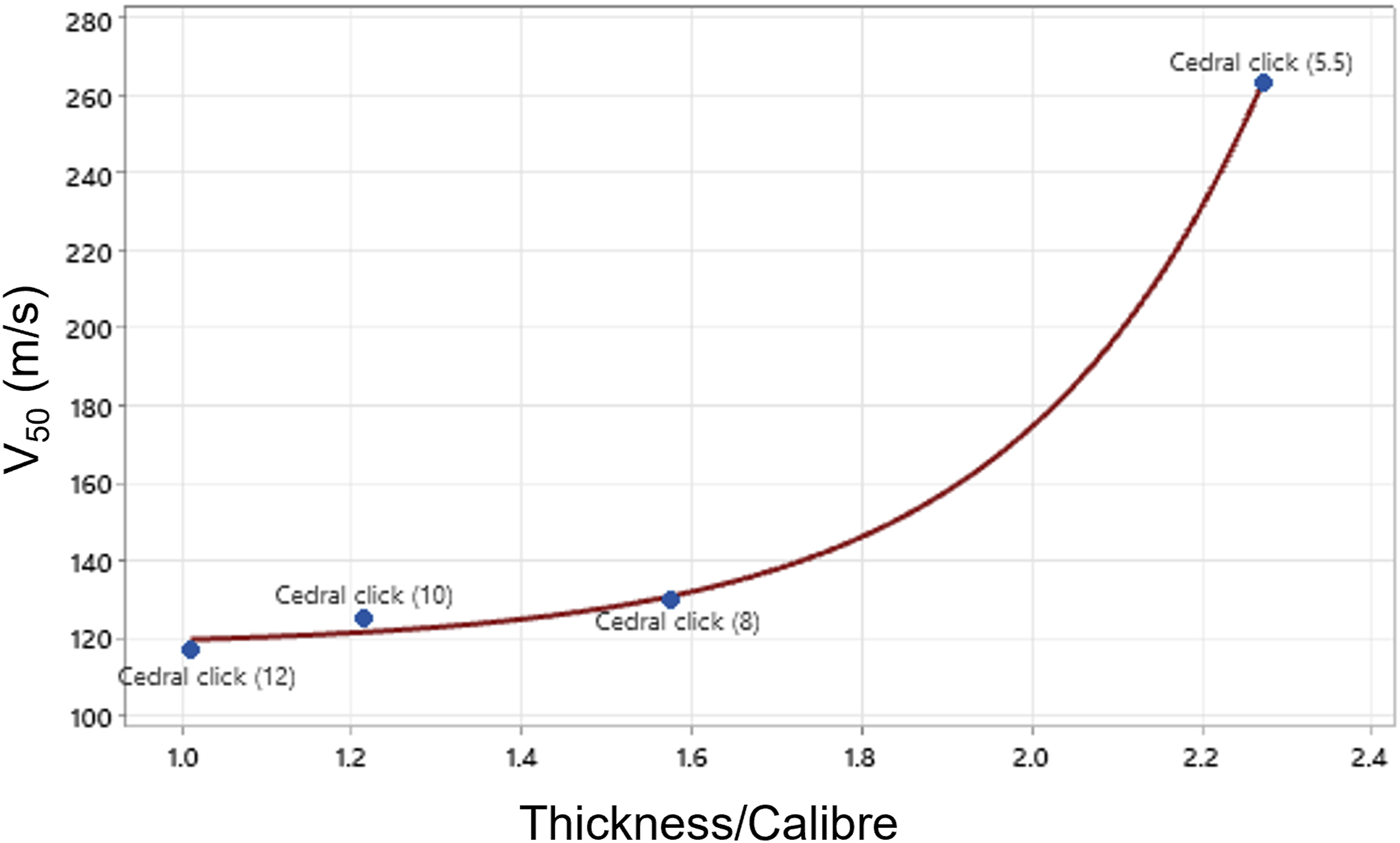
Deep penetration models
Penetration of a rigid projectile into semi-infinite targets can be modelled by looking at the deceleration of the projectile as it moves through the target. Penetration depth is given by equation (2) where V0 is the impact velocity (full derivation in (Rosenberg and Dekel, 2016)).
The general expression for deceleration depends on impact velocity as is given in equation (3) (Backman and Goldsmith, 1978; Rosenberg and Dekel, 2016).
Constants A, B and C are then determined empirically for each experiment. Forms of this equation suggested by Euler-Robins, Poncelet and Resal have recently been used to good effect in research of penetration of wooden and engineered wood targets (Koene and Broekhuis, 2017, 2019; Koene and van der Worp, 2022; Koene and Willemsen, 2023; Sanborn, 2018).
The Euler-Robins penetration equation uses just one constant which is related to the cohesive resistance of the target (Backman and Goldsmith, 1978). Assuming the mass of the penetrator does not change, integration of equation (3) as shown by Rosenberg and Dekel (2016) gives equation (4).

The non-linear regression analysis function was used in Minitab (Minitab, 2025) to obtain the value for C for each material. The constant C ranged from 231 for plasterboard to 5588 for bamboo showing a significant difference in regression models for each product. No relationship was found between the constant C and basic target properties such as thickness and density. Therefore, further material property testing is recommended to identify potential predictors of the constant. The standard deviation (S) ranged from 0.29 (Durasid) to 3.05 (Millboard) with an average of 0.96.
Deep penetration models are used in design guidance to calculate the thickness required to prevent perforation for various materials including wood and steel (Department of Defense, 2017). Sanborn (2018) successfully recalibrated this and other models to fit experimental data for penetration depths into cross laminated timber. Whilst the Euler-Robins equations have some utility in predicting penetration distance in the first part of the impact, they do not consider the maximum penetration thickness limit discussed in Section 4.4. If equation (5) is rearranged to calculate V50 using the material thickness then a significant over-prediction would occur, especially in materials with low P/T ratios. This was also highlighted by Swinea et al. (2024) during research on enhanced cross laminated timber where a reduction factor, R, was required as a calibrated factor to account for the reduced resistance near the rear face. Since P/T is also influenced by the calibre of projectile and no relationships were found between P/T and thickness/calibre it is unlikely that a model or reduction factor can be found for each material and all projectile sizes. Due to the huge range of potential projectile, shapes, sizes and velocities that may be found in terrorist devices it is unlikely that an accurate calibrated model can be achieved without vast datasets. Therefore, deep penetration models are not recommended for use in predicting perforation resistance of cladding materials due to the rear face effects that influence the failure of the material.
Carbon versus protection
To investigate the impact of embodied carbon on V50, a material property bubble chart was plotted of GWP taken from Table 1 against the Probit V50 results in Table 3. The bubble sizes illustrate the cost/m2 of the material (not including fixings or accessories) as shown in Figure 19. Bubble chart of GWP and Probit V50 with bubble size indicating cost/m2.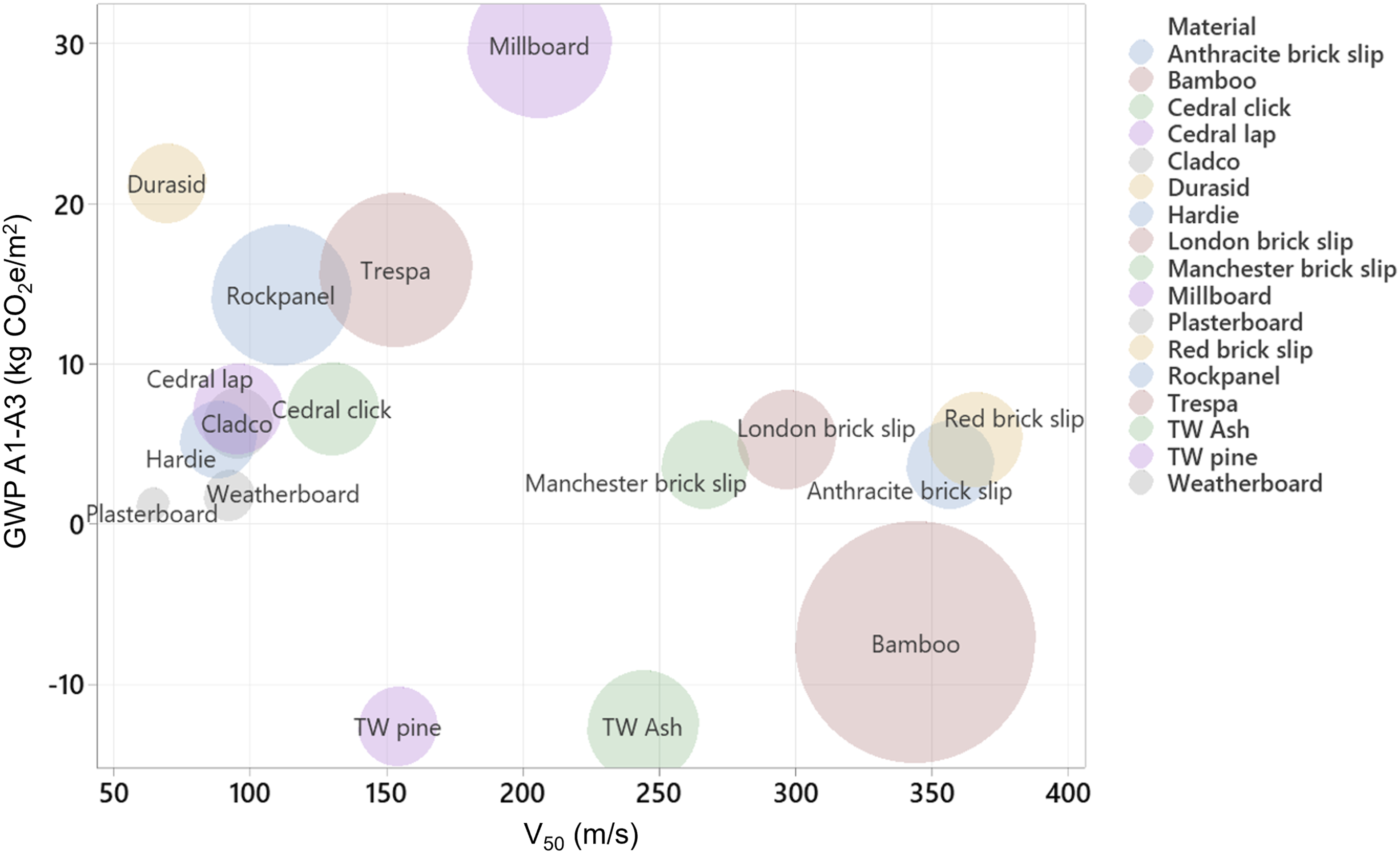
From Figure 19 it is evident that lower embodied carbon materials offer comparable impact resistance and decreasing GWP does not decrease protection level. For reference, the traditional single skin brick outer wall would have a GWP of 27.2 kgCO2e/m2 calculated from The Brick Development Association (2019). The bubble size can be used to compare cost between materials and if designers have a cost constraint or an affordability issue, materials with smaller bubbles can be selected.
The brick slips provide a good balance of protection, low GWP and relatively low cost shown in Table 1 and by the bubble size in Figure 19. The method of fixing the brick slips may increase the GWP especially if they are mechanically fixed with aluminium rails, however, this is also likely to provide additional protection from both blast and fragmentation. The bamboo composite provides the greatest protection for a low GWP, but costing over four times as much as the Thermowood ash it is likely to be prohibitively expensive for large scale use in many projects.
For many years the Ashby Material Selection Charts (Ashby, 2009) have been useful tools for designers, engineers and specifiers to identify suitable materials for a range of applications. They have also been updated to include sustainability and environmental impact metrics (Ashby, 2021; Stichting Sustainability Impact Metrics, n.d). It is possible to apply material groupings to the GWP versus V50 test data to understand where various types of materials may fall and therefore select one with the appropriate fragmentation protection and carbon cost. This is shown in Figure 20. Bubble plot of GWP versus V50 with material groupings.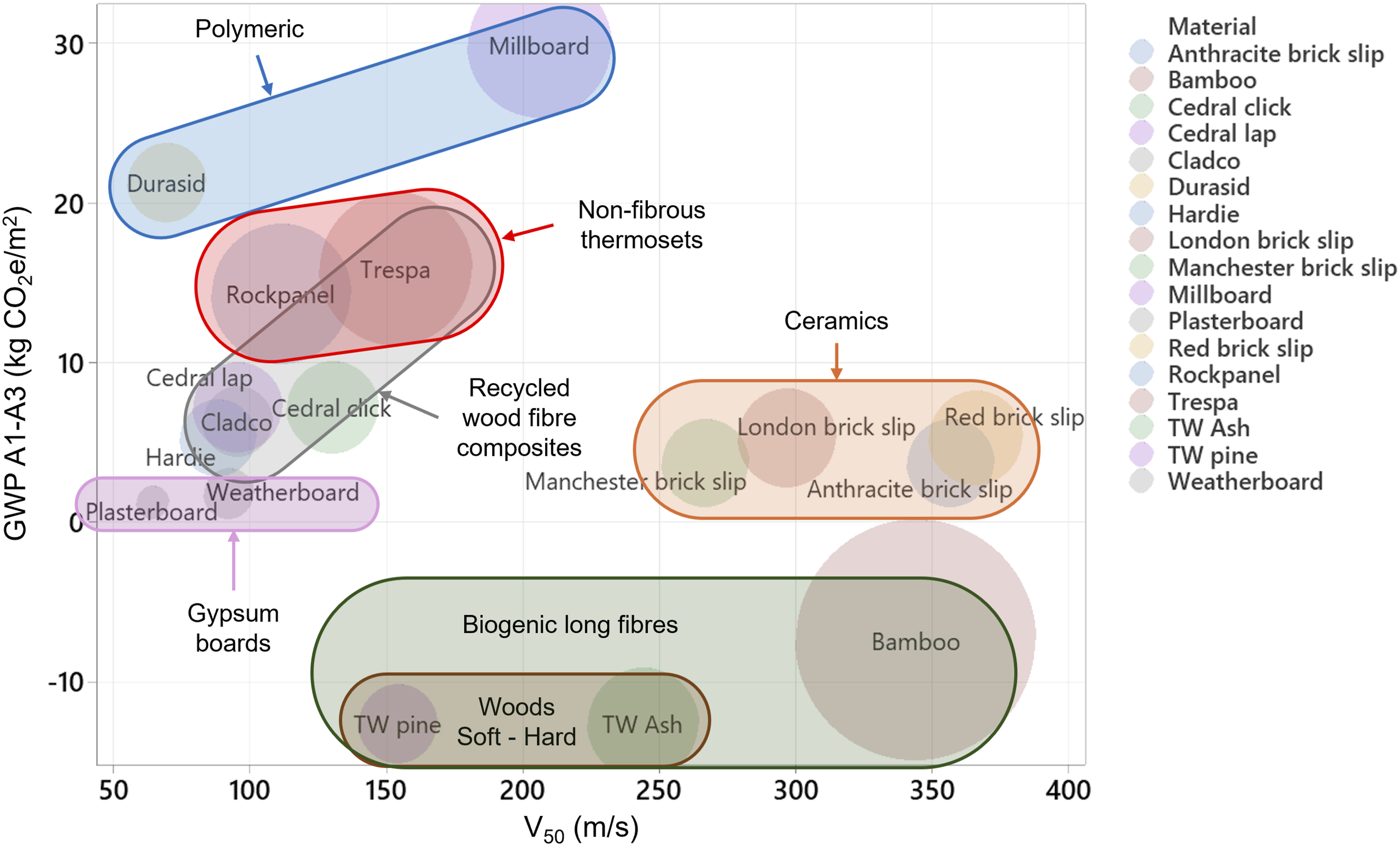
The plot shows that the GWP is highly dependent on how much processing is involved and how natural the raw materials are. The most natural being the woods which provide a medium level of protection. The processing and addition of a resin makes the bamboo composite GWP slightly higher, but it also significantly increases the protection level. The polymeric based products range from low protection from Durasid to medium protection from Millboard due to the addition of the fibres. The recycled wood fibre composites span the low to medium V50 and GWP range. The chart shows that the ceramics are a good compromise between protection and GWP at a price comparable to other materials. This type of chart is a useful tool for material selection if protection and GWP are important to the client, and it may also enable the prediction of fragmentation impact performance against GWP for similar materials within these groups.
Limitations
This study identified the V50 of a variety of materials, to an accuracy which enabled the comparison of products. The main limitation was around the testing of the ceramics where no CPs were obtained testing the brick slips. In construction, the slips that were tested are designed to be adhered to a cement board backing panel (e.g. The Brick Tile Company (2025)). The panel is likely to prevent the bricks shattering by maintaining fragments after the radial cracking occurs and will provide an additional 12 mm thickness of material to be penetrated. Brick slips can also be mounted on metal support rails which would also provide another layer to resist penetration, increasing the V50 considerably. Therefore, it is recommended that the slips are mounted on a backing product to establish an accurate V50. It must also be noted that a fragment could penetrate the mortar between the brick slips. A complete test would include the full brick/mortar/backing combination striking both the bricks and the mortar joints. The dimensions of the samples were limited to 150 mm or the actual product size and introducing longer lengths and realistic support conditions for cladding would improve fidelity. Where convergence warnings were issued to calculate the Probit V50, further samples would improve accuracy and at least 15 tests are recommended.
Conclusions
As the construction industry strives to reduce carbon in infrastructure, the use of lower embodied carbon materials is becoming more widespread. This study has demonstrated that different external cladding materials exhibit a wide range of fragment penetration resistance, which is crucial for evaluating their protective capabilities. By investigating the dynamic impact of ball bearings, the V50 ballistic limit could be established for each material allowing a comparison of performance. Materials could be grouped as fibrous, non-fibrous and ceramics with each category displaying similar failure mechanisms. The dominant mechanisms observed were: petaling and fragmentation for fibrous materials; fragmentation and petaling for non-fibrous; and radial/brittle failures for ceramics. Plug formation was observed for all fibre cement board targets and one composite.
When considering predicting protection levels, target thickness and areal density showed a weak positive correlation with V50, and material groupings can be used to further refine linear correlations. It is recommended that future research explores additional material properties and testing methods to achieve stronger correlations and enhance the understanding of protective performance. The critical penetration depth ratio varied considerably between materials and with ball bearing diameter. This implies that rear face effects play a dominant role in the penetration process and therefore the protection level. Ball bearing size also affected the V50, plateauing with diameters over 8 mm. This suggests that 8 mm ball bearings can represent a dangerous IED fragment size which balances penetration speed and fragment quantity. Deep penetration models are not recommended for use to predict the V50 due to the omission of the critical thickness parameter P/T. Since ball bearing size also influences P/T further empirical testing with a variety of projectile sizes for each material would be required to establish the relationship.
Protection levels varied considerably across the tested materials, but they were not dependent on the GWP of the product. Importantly, materials with lower embodied carbon levels (shown by GWP) did not necessarily compromise protection levels. The novel material selection chart developed during this study provides a visual representation of fragment protection, carbon content and cost. By comparing these factors designers can make informed decisions when selecting materials that meet both embodied carbon and protection requirements. However, it should be noted that the highest V50 results were below those expected from blast driven ball bearings implying that wall perforation remains a risk. This emphasises the need for further work on full wall buildups to ascertain whether core and internal layers provide sufficient resistance to prevent injury from blast-driven fragmentation that fully penetrates a wall.
Footnotes
Acknowledgements
This work was supported by the British Army [External Placements (Academic) Full-time Programme] and Cranfield Forensics Institute. The authors also wish to acknowledge the support of the workshop staff: Andy Crocker, Andy Roberts, and Xander Hadgkiss and for their assistance with preparing materials and operating the gas gun, and to the Cranfield Learning Enhancement and Design team for graphic design support.
Ethical considerations
Ethical approval was obtained under reference: CURES/21215/2024 Project ID: 23908.
Author contributions
Funding
The authors disclosed receipt of the following financial support for the research, authorship, and/or publication of this article: this work was supported by the British Army External (Academic) Placements Scheme.
Declaration of conflicting interests
The authors declared no potential conflicts of interest with respect to the research, authorship, and/or publication of this article.