
Abstract
Ensuring blast protection for existing buildings, especially addressing the vulnerability of conventional windows, is a significant challenge. Such unprotected windows can shatter even with moderate blast loads, posing a substantial risk of injury to occupants. This article discusses experimental research on enhancing the blast protection of single casement windows with insulating glass units and frames made of unplasticized polyvinyl chloride (uPVC). A retrofit concept using anti-shatter films, metallic sash reinforcements, adhesive bonding of the glazing to the sash frame, and a burglary resistance fitting-system was developed and tested in an explosion-driven shock-tube. Moreover, novel patches made of glass fiber-reinforced polymer applied to the corners of the window frames have been tested and proven effective in providing additional strength to the window. The study concludes that the tested combination of retrofit measures can significantly reduce hazards from window fragments without compromising functionality or aesthetics.
Keywords
Introduction
Several ongoing security challenges require a reassessment of the need for structural protection against explosive events. Major bomb attacks, such as in Oslo in 2011 or Brussels in 2016, underscore the vulnerability of public spaces, while explosion accidents, such as in the port of Beirut in August 2020, lead to discussions about safety requirements of exposed areas. Since the beginning of 2022, in the light of the war in Ukraine, the protection of critical infrastructure has come to even greater prominence.
Previous test series have shown that conventional windows with window frames made of flexible materials such as unplasticized polyvinyl chloride (uPVC) or wood are particularly vulnerable to blast loads (Andrae et al., 2024). Annealed glass, which is primarily used in conventional windows, can shatter into sharp shards that may cause lacerations (Fletcher et al., 1980; Solomos et al., 2020). Besides glass breakage, the shock wave has the potential to detach the window frame from its mounting (Andrae et al., 2024). The resulting heavy fragments of the frame can result in blunt trauma if they hit individuals (Fletcher et al., 1974).
In order to subsequently increase the safety of building occupants during explosion events, three protection concepts for windows are possible: • • •
Many buildings, especially those with historic significance or limited budgets, may not have the flexibility for extensive window replacement. Simply closing existing window openings can be very disruptive to the comfort of building occupants.
This article addresses the concept of retrofitting a window to reduce the risk of injury in the event of an explosion. Retrofitting existing windows to resist blast loads is often a practical compromise that allows for a relatively simple and quick process compared to window replacement. The goal of this method is to preserve the original structure of the window while providing maximum safety.
Over the past two decades,
The brochures (NPSA, 2013a, 2013b, 2013c) of the UK National Protective Security Authority (NPSA), offer insights into the essential characteristics of ASFs concerning blast protection. The total film thickness typically required for blast protection ranges from 0.1 mm to 0.5 mm, depending on factors such as the level of protection needed and the size of the glazing. It is important to highlight that the long-term durability of ASFs has yet to be definitively evaluated (Mattei et al., 2022).
ASF-retrofitted glazing that has undergone blast testing currently meets resistance class ER1 according to EN 13541:2012. This classification indicates the ability to withstand a blast load with a reflected peak overpressure
As demonstrated in (Andrae et al., 2024), ASF-reinforced glass units installed in conventional uPVC windows do not achieve the expected explosion resistance (ER1) as observed in the certification test. Figure 1 displays a high-speed video recording of the respective test series. After approximately 20 ms, the ER1 blast-load tore the entire window sash from the window frame. Secondary debris was propelled at a velocity of up to 15 m/s into the interior of the building. A post-test risk assessment reveals a predominantly substantial risk of injury, indicating low effectiveness of the protective measure. Conventional uPVC window with an ASF-reinforced glass unit in a ER1 shock-tube test at the Fraunhofer EMI, from (Andrae et al., 2024).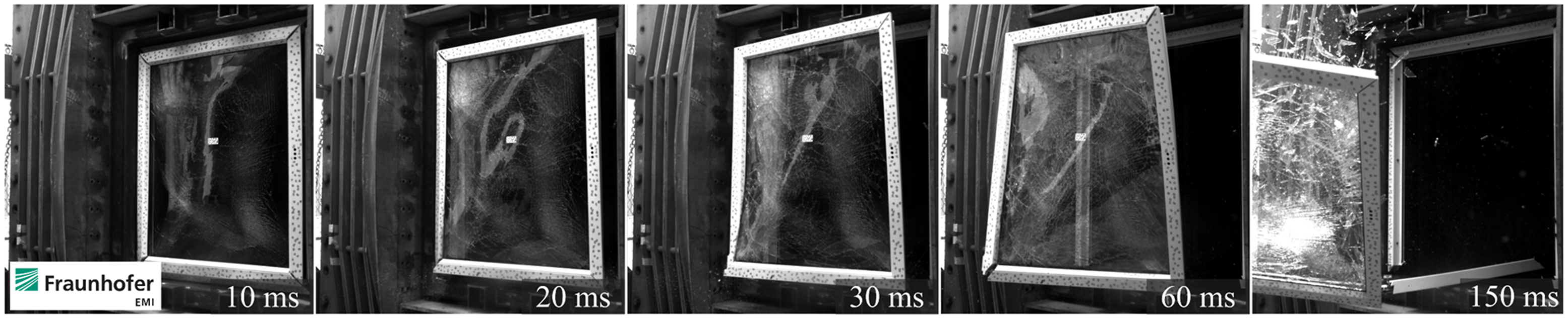
If it is anticipated that window fragments are torn off during an explosion, • Catcher-cables or catcher-bars may cut impacting ASFs, making them ineffective in catching fragments. • ASFs impacted can be torn off from the window frame and become wrapped around catcher-cables or catcher-bars. This may result in detached glass fragments being propelled into protected areas. • Blast curtains need to remain closed at all times, which could potentially disrupt comfort inside the building.
In summary, ASFs and catcher systems are frequently utilized as retrofit measures, with a primary focus on mitigating the risk posed by glass fragments and, when necessary, catching fragments from shattered windows. The retrofitting measures that are commonly used often do not provide the same level of protection as a blast-resistant window. Propelled fragments of the window can still cause secondary explosion injuries (lacerations, blunt traumata, etc.).
These limitations underscore the importance of careful design and implementation of new retrofit systems. The existing literature shows a notable lack of studies that specifically address methods for strengthening vulnerable components of conventional windows. For uPVC windows, possible weak points are the frame corners (torsional failure), the fitting system (tear-off failure), and the attachment of the ASF to the frame in post-fracture behavior (Andrae et al., 2024).
This article discusses new experimental research on the protection of conventional single casement windows with insulating glass units (double-paned) and uPVC window frames. To harden the windows, various retrofit configurations are being tested in an explosion-driven shock-tube. The windows are retrofitted by using anti-shatter films, metallic sash reinforcements, and an RC3 burglar-resistant fitting system. The glazing is bonded to the sash frame by using an adhesive. In addition, novel patches made of glass fiber-reinforced polymer are tested which enhance the resistance of the frame corners of the window. The proposed configurations are designed to avoid significant disruption to building occupants (non-invasive retrofitting).
Experimental setup
In the following, an overview of the test configurations, including the number of repetitions, is given. A total of five shock-tube tests are performed at the same blast load intensity: • Basic configuration V0 represents an unprotected window, with an installed fitting-system for burglary-resistance class RC3 (EN 1627:2021). One test is performed. • Configuration V1 is a retrofitted version of the basic configuration V0; it is retrofitted with anti-shatter films, metallic sash reinforcements, and by bonding the glazing to the sash frame with an adhesive. One test is performed. • Configuration V2 is an updated version of configuration V1; in addition to all retrofit measures used for configuration V1, it is retrofitted with patches made of glass fiber-reinforced polymer, that are bonded and bolted to the frame corners of the window. Three tests are performed.
Basic configuration V0 – unprotected
Figure 2 shows the basic configuration which is a conventional single casement window with an insulating glass unit (IGU) and window frames made of uPVC. Basic configuration of the tested uPVC-window, (a) top view (b) cross-section.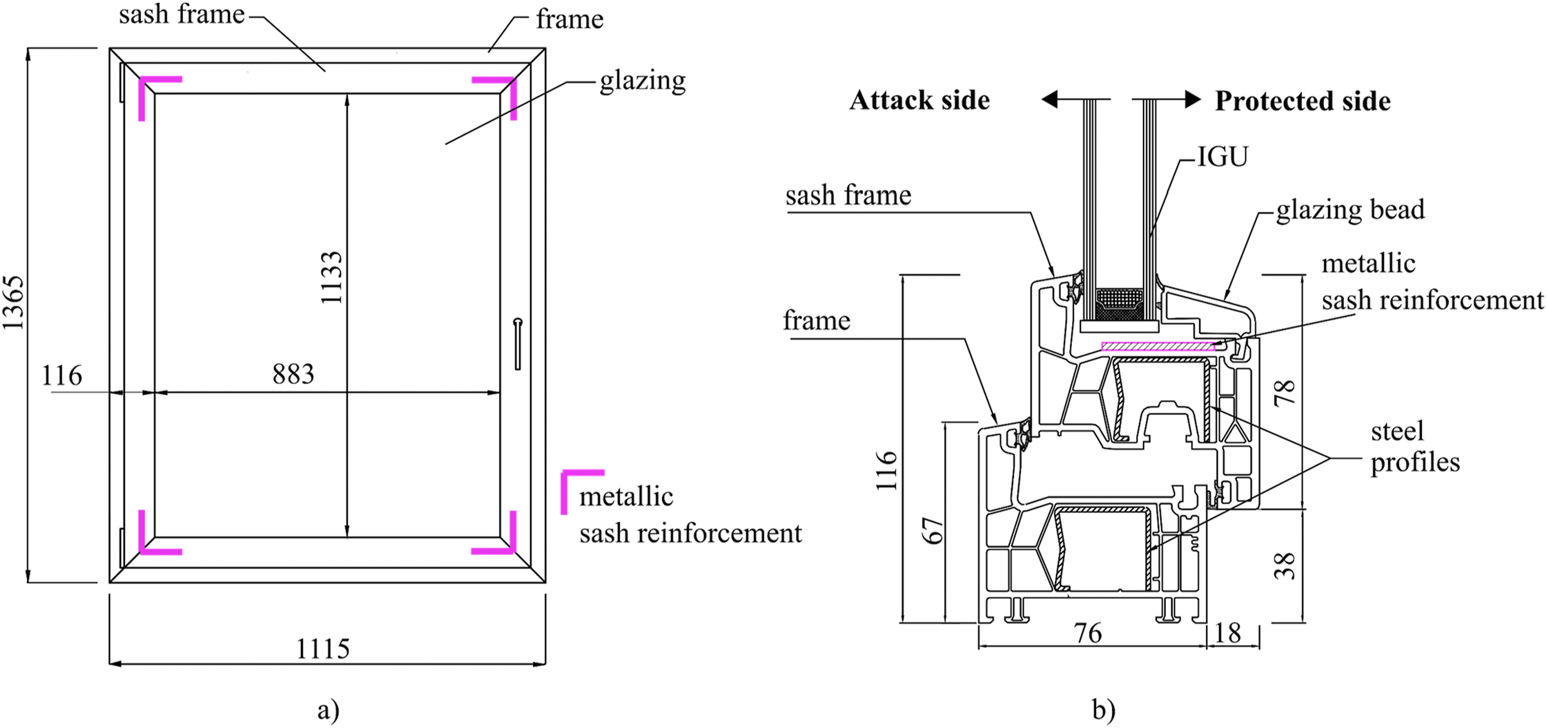
The installed IGU consists of an outer pane of annealed float glass, 4 mm thick, a 16 mm wide cavity filled with an argon gas mixture, and an inner pane of annealed float glass, also 4 mm thick. The external IGU dimensions of 917 × 1167 mm (width x height, Figure 2(a)) are selected to correspond to the required dimensions of the EN 13541:2012 method for testing blast-resistant glazing (900 mm × 1100 mm). The IGU is embedded in the glazing rebate by 17 mm on all sides.
As it is standard practice, steel profiles are placed in the largest thin-walled hollow chambers of the frames to provide additional strength and stability to the uPVC frames (Figure 2(b)). In the tested configuration, the steel profiles do not connect the corner joints of the frames but end approximately 4 cm from the joints. Additionally, thin metallic sash reinforcements are placed in the glass rebate and are attached to the sash frame (Figure 2(a)). They provide minimum restraint in the event that the corners of the sash frame fracture.
The fittings of a casement window provide the mechanical load-bearing connection between the sash (the moveable part of the window) and the frame (the stationary part of the window). In the tested configuration, the window is equipped with a burglary-resistance fitting-system. The types and arrangement of the strike plates are depicted in Figure 3(a). The fitting system consists of 16 security strike plates, one security tilt strike plate and two corner bearings. According to the manufacturer, the installed fitting-system is suitable for achieving resistance class RC3 against burglary (EN 1627:2011). It is designed to protect against forced entry with simple tools such as screwdrivers, pliers, wedges, and crowbars. (a) Arrangement of the fitting system, (b) arrangement of the anchors.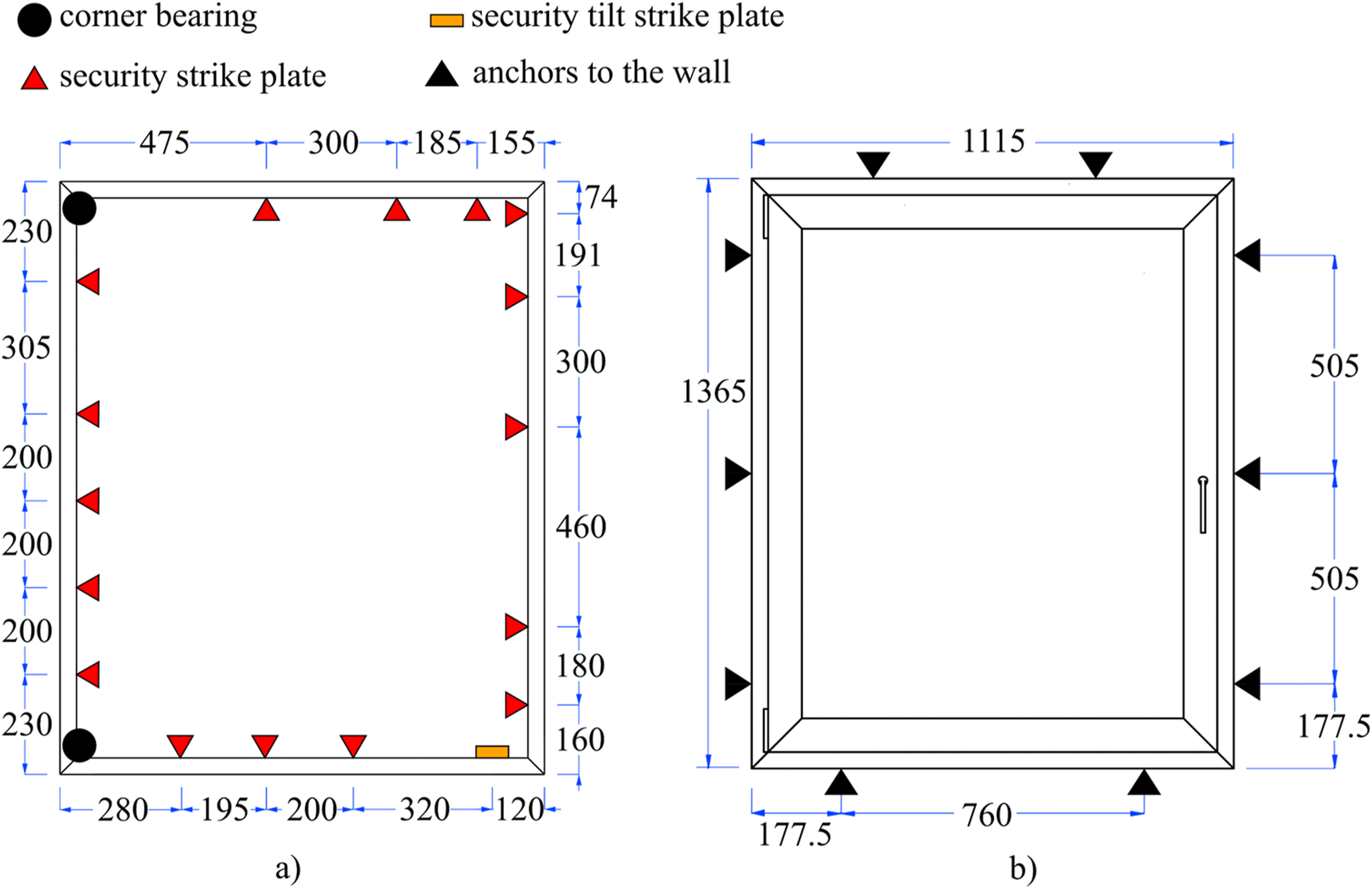
Eight M8 stainless steel screws are used to anchor the uPVC window in the module box of the shock-tube. The positions of the anchors are indicated in Figure 3(b).
Configuration V1 – without patches
Configuration V1 is a retrofitted version of the basic configuration V0. Details of the additional retrofit measures implemented (Figure 4) are discussed below. Retrofit concept for the glass unit and the sash frame.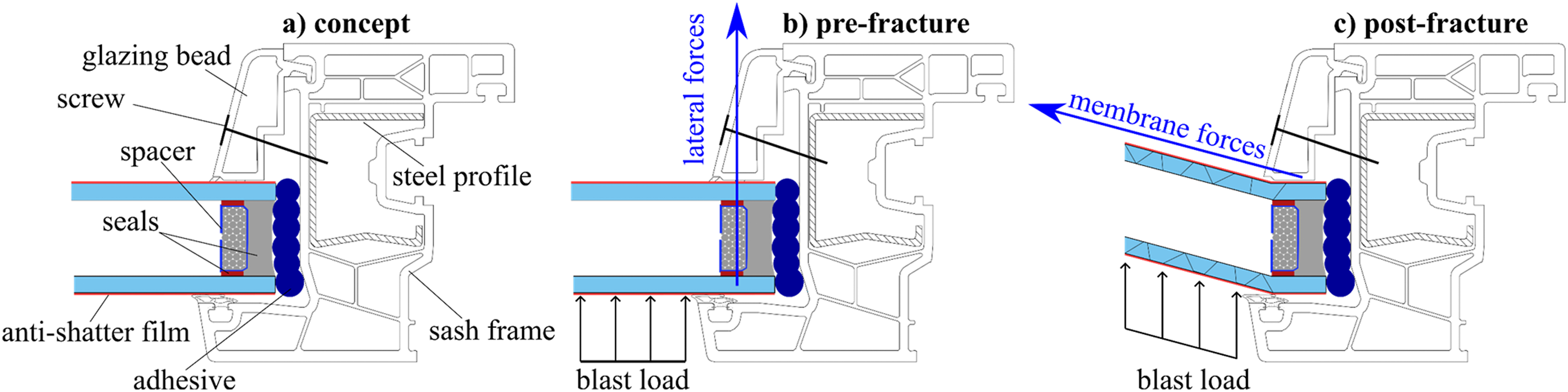
The IGU is retrofitted with ASFs
In the tested configuration, ASFs are applied on both glass panes of the IGU (Figure 4(a)). As tested and verified by the manufacturer in the EN 13541:2012 test procedure, the application of the ASF to an IGU would achieve resistance class ER1. If the glass panes shatter (post-fracture, Figure 4(c)), the fragments still adhere to the ASFs and the protective mechanism is engaged.
The IGU is bonded to the sash frame
In the post-fracture mode (Figure 4(c)), the used ASF creates a web-like pattern that keeps the shattered glass in place, reducing the risk of injury from glass shards. However, if the ASF is not securely attached to the sash frame, the ASF including the adhered glass fragments are propelled into the protected area (Remennikov et al., 2008).
In this test series, a novel approach is investigated that utilizes the effect of shattered glass still adhering to the primary and secondary seals of the glazing spacer. This protective concept involves adhesive bonding of the glazing to the sash frame (Figure 4(a)). Sikaflex-553 is injected into the glazing rebate between the spacer of the glazing and the sash frame. The bonding is intended to bridge the gap in the glazing rebate and enable the membrane effect of the ASF after glass breakage (Figure 4(c)).
The glazing beads are attached to the sash frame with self-tapping screws
During blast loading, high lateral forces are transferred from the glazing to the glazing beads (Figure 4(b)). To prevent the glazing beads from tearing out of the sash frame, they are secured in the tested configuration with self-tapping screws. The used screws are anchored in the steel profiles of the sash frame, spaced 350 mm apart along the glazing beads.
Configuration V2 – with FRP patches
Configuration V2 is a revised retrofitted version of configuration V1. In addition to the retrofit measures described above, novel patches made of glass fiber-reinforced polymer (GFRP) are employed to strengthen the corner joints of the window frames. As the frame corners are anticipated to be vulnerable parts of the window frame (Andrae et al., 2024), the patches are designed to provide additional support in the event of failure.
GFRP is known for its high strength-to-weight ratio and durability, making it attractive for many structural and industrial applications (Bohmann et al., 2018). It is a composite material made by combining glass fibers with a polymer matrix. The polymer matrix keeps the fibers in place for load introduction and load transfer between individual fibers, provides resistance to fiber buckling under compressive loads, and protects against environmental influences.
Material parameters of the GFRP-prepregs (Gebhardt et al., 2023).
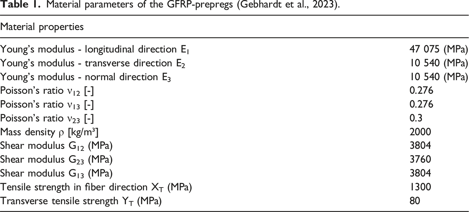
The produced laminate has a quasi-isotropic layered structure [0°/45°/90°/−45°]2s. Each individual layer has a nominal thickness of 0.1875 mm. The GFRP-patches consist in total of 16 layers, thus the total thickness of the patch is 3 mm. The laminate is fabricated in a hot air autoclave process as specified by the prepreg manufacturer.
Figure 5(a) shows the window sash with all applied retrofit measures. Since the glazing beads are removed, the adhesive bonding between the glazing and the sash frame, as well as the metallic sash reinforcement are visible. Figure 5(b) shows two of the applied patches at the frame corners. (a) Frame corner of a retrofitted sash frame including GFRP patches (here: glazing bead are removed), (b) GFRP patches applied at the frame corners.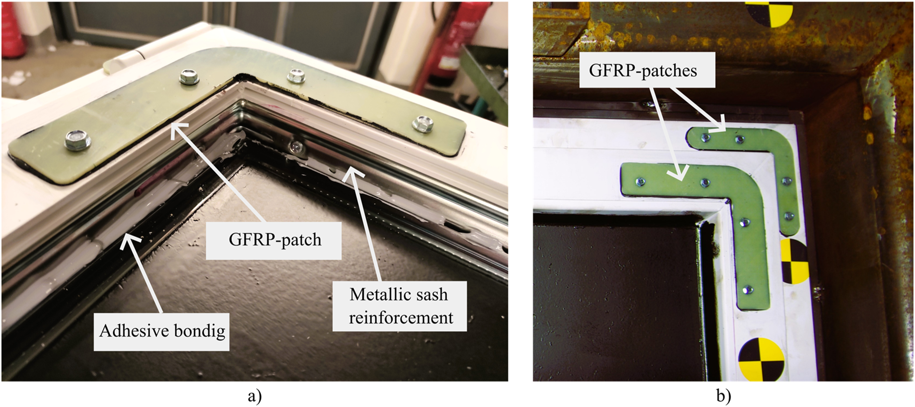
To attach the GRP-patches on the window frames, recesses of 1.5 mm depth are milled. Subsequently, the surfaces on the uPVC-frames and on the GFRP-patches are pre-treated with sandpaper and cleaned with isopropanol. Bonding is accomplished using GP49, a 2-component adhesive. Each of the GFRP-patches are positioned in the recesses promptly after the application of the adhesive and pressed on manually. Next, four self-tapping screws are placed for each GFRP-patch (Figure 5(b)). By tightening the screws, contact pressure is created during the curing of the adhesive.
Shock-tube facility
The experimental investigations are carried out in the explosion-driven shock-tube of the Bundeswehr Technical Center for Protective and Special Technologies (Figure 6, WTD 52). More detailed descriptions of the shock-tube can be found in (Millon and Haberacker, 2017). Basic configuration of the tested uPVC-window, (a) top view (b) cross-section.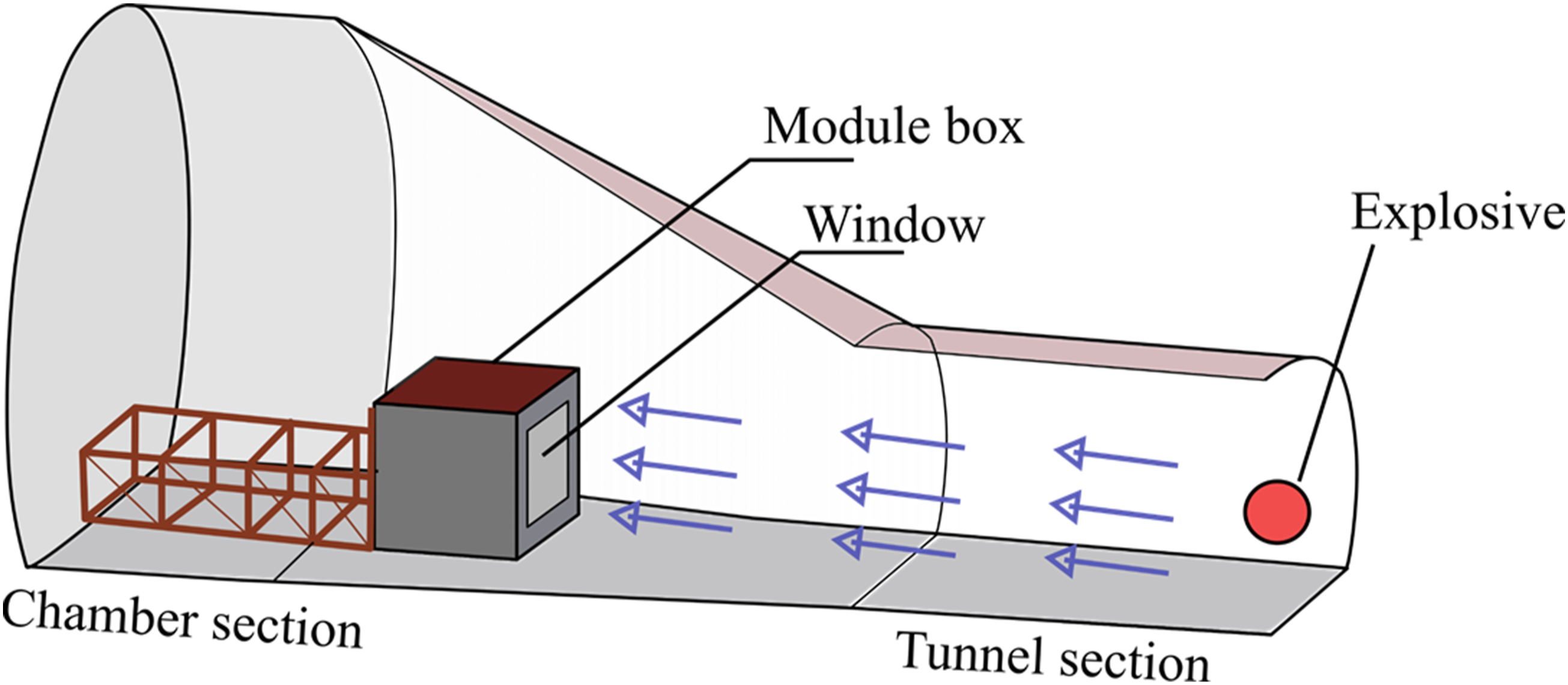
The shock-tube is composed of two parts: a tunnel section and a chamber section. The detonation of the explosive (PETN) takes place in the tunnel section of the shock-tube. A walk-in module box is installed in the chamber section. The dimensions of the module box are 3.6 m × 4.5 m × 7.35 m (height × width × length). The tested windows are mounted at the wall facing the explosive charge. Due to the adequate length of the tunnel section, a planar shock front is subjected to the module box.
Instrumentation and documentation
Several measuring systems are used to obtain test data.
Prior to the tests, the ambient air temperature, the surface temperature of the glazing, the ambient pressure and the relative humidity are measured.
During the tests, the reflected blast loads subjected to the window are measured using six pressure gauges (Figure 7(a)), which are arranged at the wall of the module box facing the explosion (Figure 6). The pressure gauges used are Kulite XT-190 (M), which can measure up to 105 kPa of overpressure with a maximum error of 0.5% (Kulite 2014). The pressure data is recorded at a sampling rate of 50 kHz in order to capture all high-dynamic effects. (a) Arrangement of the pressure measurement sensors and the high-speed video cameras at the module box, (b) arrangement of markers at the window surface.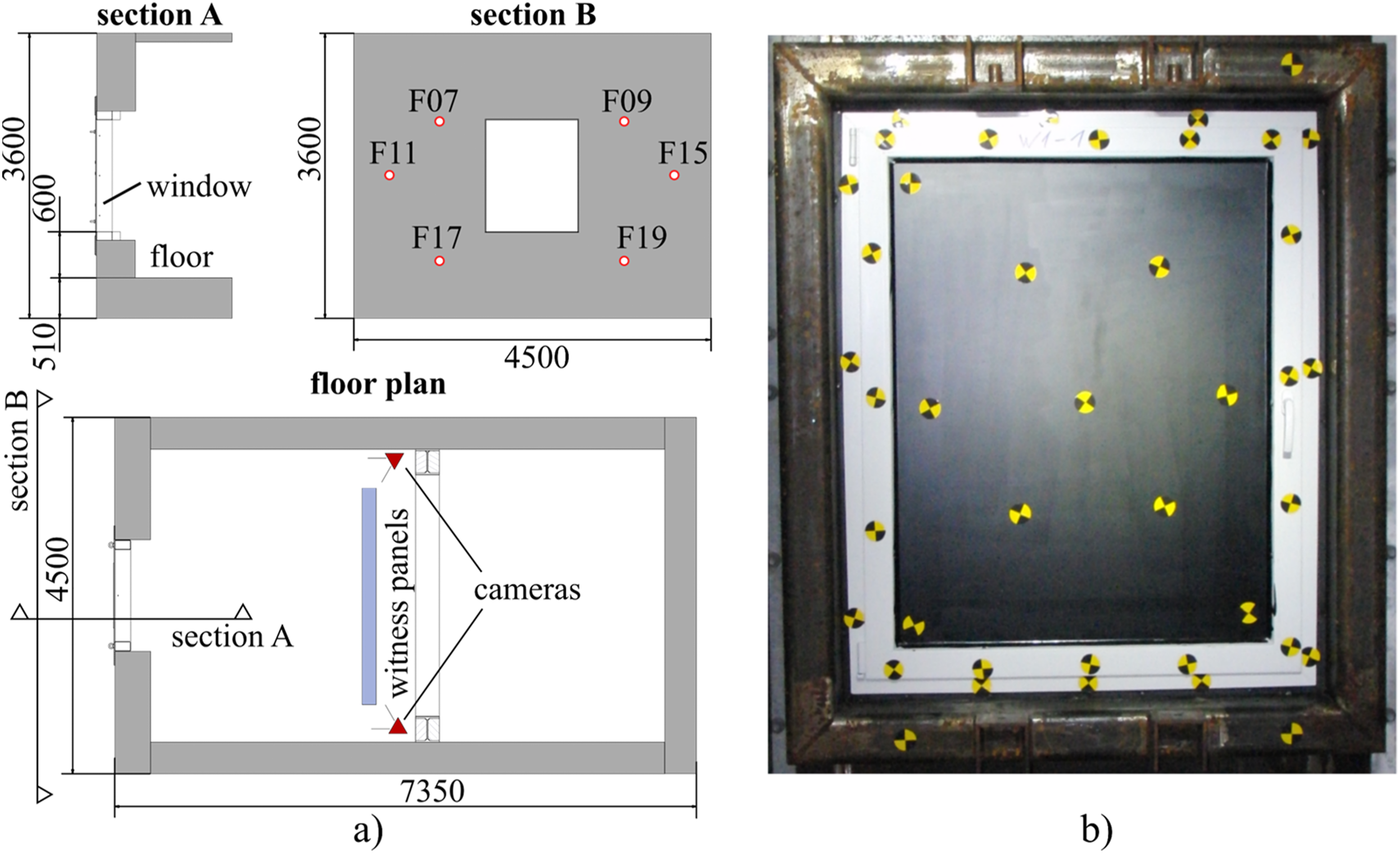
Moreover, during the tests, the displacements of the tested window are recorded using an optical measurement system that is arranged inside the module box. Figure 7(a) shows the experimental setup in the floor plan with the positioning of the two high-speed video cameras. The cameras are positioned at an angle of 35° to the front wall and focused on the center of the window. The kinematic data is obtained using the Digital Image Correlation (DIC) method. Spatial displacements of markers placed on the glazing and frames (Figure 7(b)) are analyzed in the direction perpendicular to the glass panes. Using a new set of markers, the cameras were calibrated prior to each test. The recorded videos have a resolution of 1280 × 800 pixels at a frame rate of 5000 frames per second. The spatial positions of the measuring markers are therefore determined every 0.2 ms.
After the tests, the damage to the window is analyzed in detail and any fragments that may have been torn off are recorded.
Hazard assessment
To evaluate the hazards posed by window fragments, the procedure given in GSA-TS01-2003 is adopted. The protected area is sub-divided into six zones (Figure 8), each associated with specific protection and hazard levels, summarized in Table 2. To capture the impact of fragments in zones four and 5, witness panels are positioned at a distance of 3.0 m from the tested window. Protected area sub-divided into six zones for hazard assessment and acceptability of hazards according to (UNDSS, 2021). Performance conditions according to GSA-TS01-2003.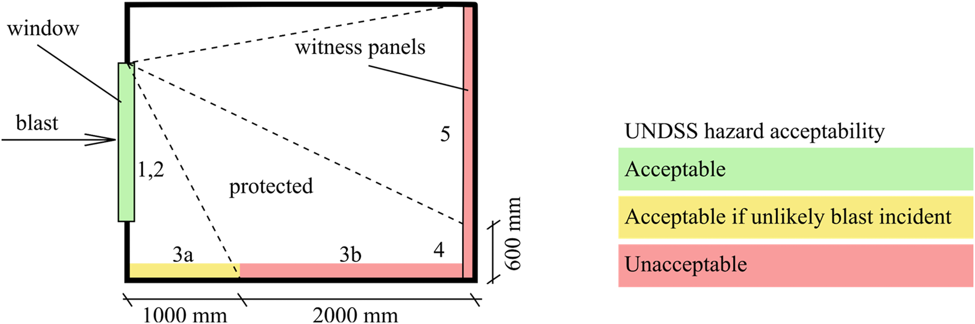
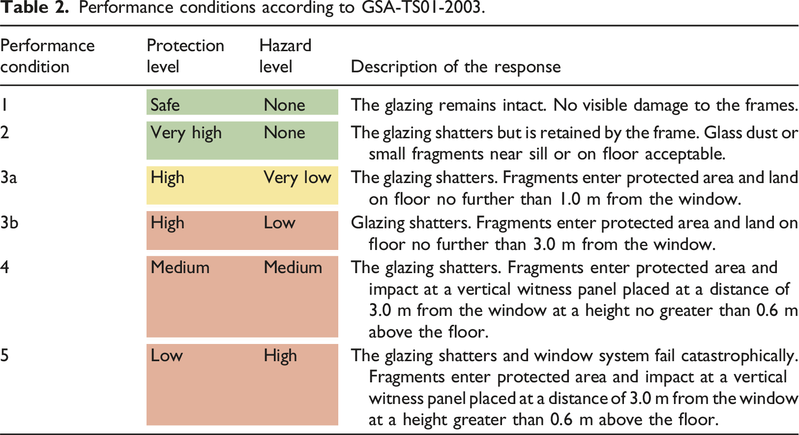
The United Nations Department of Safety and Security (UNDSS) defines the hazard acceptability based on the performance conditions of GSA-TS01-2003 (UNDSS, 2021). According to the bulletin, performance conditions one through 3a are considered acceptable for UN buildings (Figure 8). Performance condition 3b would be accepted if the blast incident is an unlikely event. Performance conditions four and five are not acceptable. The defined hazard acceptability is considered in the evaluation of the shock-tube tests.
Note that the methodology of the UNDSS bulletin does not quantify the probability of explosion events. In general, the risk of fatalities from explosion events is often low (Stewart and Netherton, 2019). Consequently, identifying an “unlikely blast incident” is not straightforward. Ultimately, residual risks must be acceptable.
Test results
In the following, the measured blast loads are analyzed, and the results of the five shock-tube tests are presented and discussed.
Blast load
Figure 9 shows the 30 measured reflected overpressure-time histories of all five shock-tube tests. The average reflected overpressure time-history is calculated by interpolating the pressure for each time step. The corresponding reflected impulse-time history was derived by numerical integration of the average reflected overpressure-time history. Measured overpressure-time histories.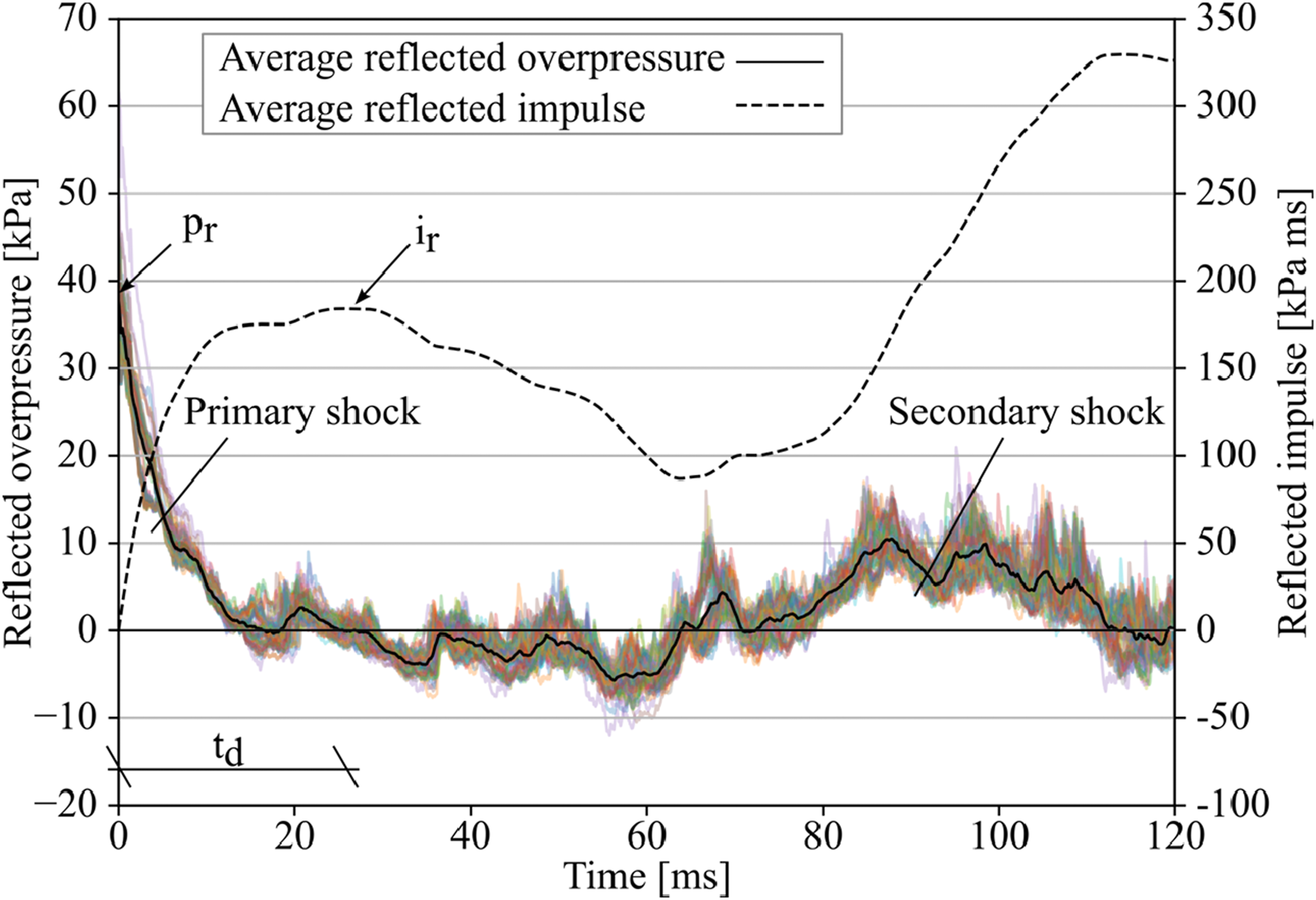
Based on Figure 9, some specific characteristics of the blast loads in the shock-tube tests and the consequences for the evaluation of the test series can be discussed. The initial rapid increase in overpressure marks the arrival of the primary shock on the specimen (Figure 9). After reaching the peak reflected overpressure
It is well known for shock-tube tests that secondary shock waves can occur due to insufficient venting and multiple reflections within the tube (Gan et al., 2020). In the conducted tests the exposure of the specimens to a secondary shock can be observed starting at about 65 ms (Figure 9). The secondary shock reaches a reflected overpressure that is about 1/4 of the peak reflected overpressure
It can be deduced that the results of the shock-tube tests may not be directly comparable to the results of free-field blast tests, as the nature of the blast loads produced in these two types of experiments can be quite different. The most significant difference is that in shock-tube tests, secondary shocks act on the test specimen, whereas in free-field blast tests, usually only one distinct primary shock acts. However, this phenomenon is well known, it is often neglected in recognized test methods for the certification of glazing, windows, and facades, i.e., EN 13541:2012, EN 13124-1:2001-10, and ISO 16934:2007. According to these standards, the reflected peak overpressure
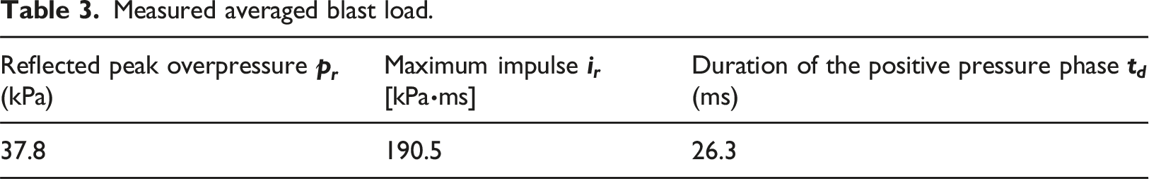
Measured averaged blast load.
In the test series presented here, high-speed video recordings are assessed to examine if the primary shock caused failure. This approach enables to anticipate the possible outcome of free-field blast tests.
Unprotected window - configuration V0
Figure 10(a) shows a high-speed video capture of the basic configuration V0 taken 33 ms after the arrival of the primary shock. The unprotected window sustained severe damage during the primary shock (time <65 ms). The glazing was shattered, and the glazing beads were torn off the sash frame. Configuration V0 (a) High-speed video capture at 33 ms, (b) deformation-time histories measured at the sash frame, (c) protected area after the shock-tube test.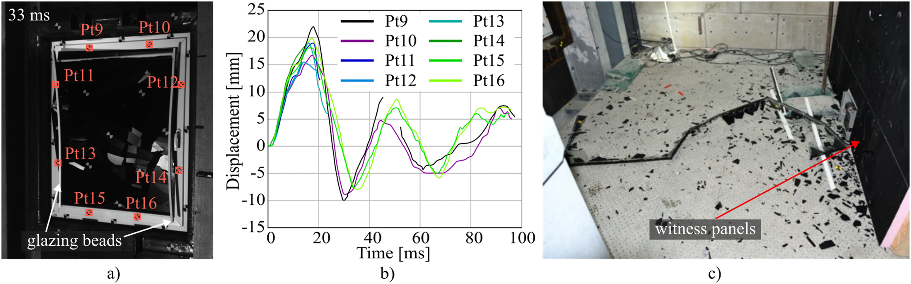
Figure 10(b) depicts the measured displacement-time histories of the sash frame at the marker points Pt9 to Pt16. The high-speed videos and the deformation-time histories reveal the following failure mechanism: • The frame profiles are deformed mainly by torsion along their longitudinal axis. As a result, after about 5 ms, separation cracks were initiated at all eight frame corners. • During the primary shock, the sash frame displaces approximately 23 mm (Figure 10(b)) but remains still attached to the frame. It rebounds rapidly at about 19 ms. The burglar-resistant fitting system was able to effectively secure the sash frame. • The glazing shatters after about 23 ms. Large glass fragments are propelled into the protected area. The glass fragments impacted at zone 5 (Figure 8) of the witness wall.
In summary, the test with an unprotected window resulted in the unacceptable
Retrofitted window without GFRP-patches - configuration V1
Configuration V1 is a retrofitted version of the basic configuration V0. In this configuration, ASFs were applied, the IGU was bonded to the sash frame, and the glazing beads were attached to the sash frame with self-tapping screws.
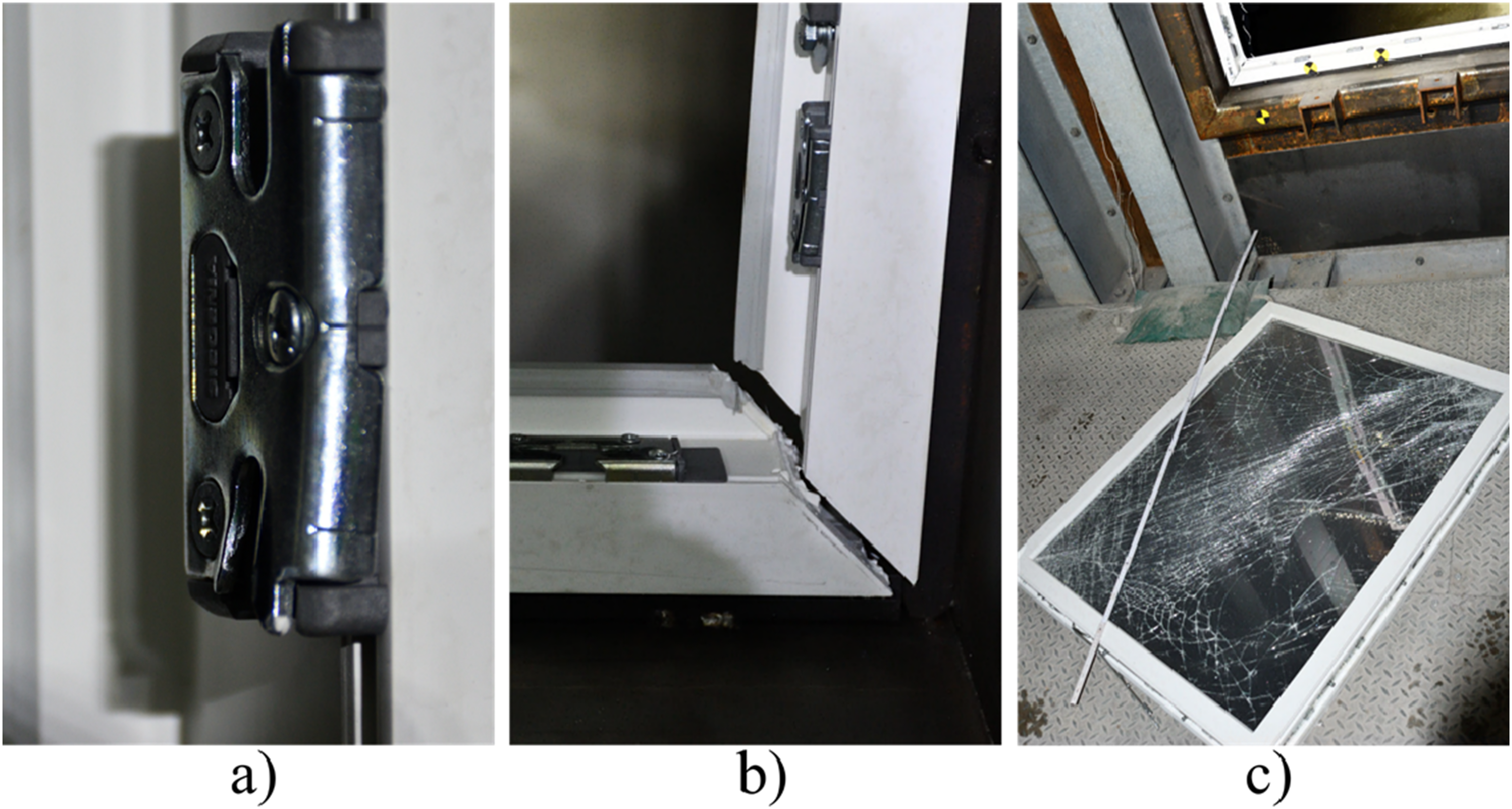
Figure 11(a) shows a high-speed video capture of configuration V1 that was taken at the end of the primary shock at 65 ms. The window appears mainly intact. During the exposure to the primary shock (time <65 ms), a maximum displacement of 59 mm was reached at the window lintel (Pt10, Figure 11(b)). The window sash remained securely attached to the frame and the glazing remained attached to the window sash. The active triggering of the fitting system is indicated by the strongly deformed strike plates (Figure 12(a)). The glazing was not shattered during the primary shock. Configuration V1 (a) high-speed video capture at 65 ms, (b) torn off window sash in the protected area. Configuration V1, (a) deformed strike plate, (b) separation cracks at a frame corner, (c) torn off window sash in the protected area.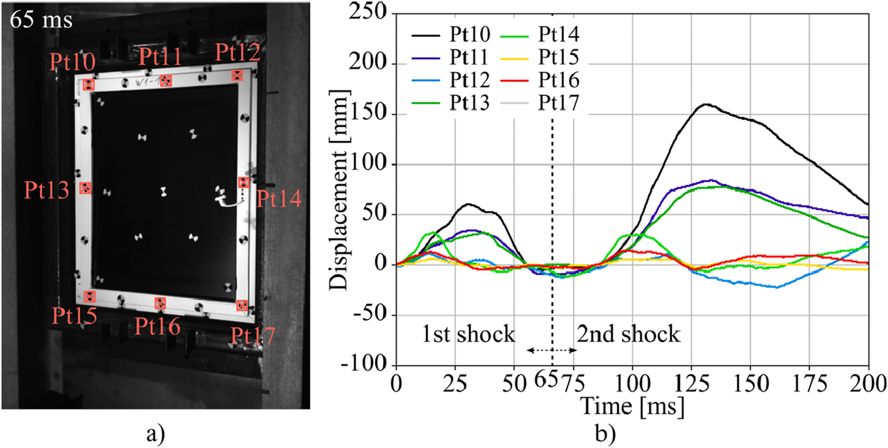
From the high-speed video recordings, it was observed that all eight frame corners of the window sustained severe damage during the primary shock. Similarly to the test in configuration V0, separation cracks at all eight corner joints of the frames began to be initiated starting at about 5 ms.
Figure 12(b) shows a respective separated corner joint after the test. The separation crack extends along the welded joint of the frame. At the sash frame (Figure 12(c)), the cracks also fully separated the uPVC profiles but extensive separation was prevented by the attached metal sash reinforcements placed under the glass rebate (Figure 2(a)).
Eventually, during the exposure to the secondary shock (time >65 ms), the fitting system of the pre-damaged window gradually loosened, most likely due to the fractured frame corners, which facilitated the sliding out of the window sash. The maximum displacement reached during the secondary shock was 160 mm (Figure 11(b)).
As a consequence of the failure of the fitting system, the window sash fell in one piece about 2.4 m into the protected area. Figure 12(b) shows the torn off window sash after the shock-tube test. The anti-shatter films (ASFs) were still attached to the sash frame. No glass fragments were observed in the protected area.
In summary, the test with a retrofitted window resulted in
Retrofitted window with GFRP-patches - configuration V2
Configuration V2 is a retrofitted version of Configuration V1. Additionally, GFRP-patches are bonded and bolted to the frame corners to close the observed weak point of Configuration V1 (separation cracks).
Figure 13 shows the three tested windows during and after the shock-tube tests. In all three tests, similar as in the test with Configuration V1, the window sashes remained attached to the frames during the exposure of the primary shock (time <65 ms). Configuration V2, high-speed video capture at 65 ms and post-test documentations of (a) Test V2.1, (b) Test V2.2 and (c) Test V2.3.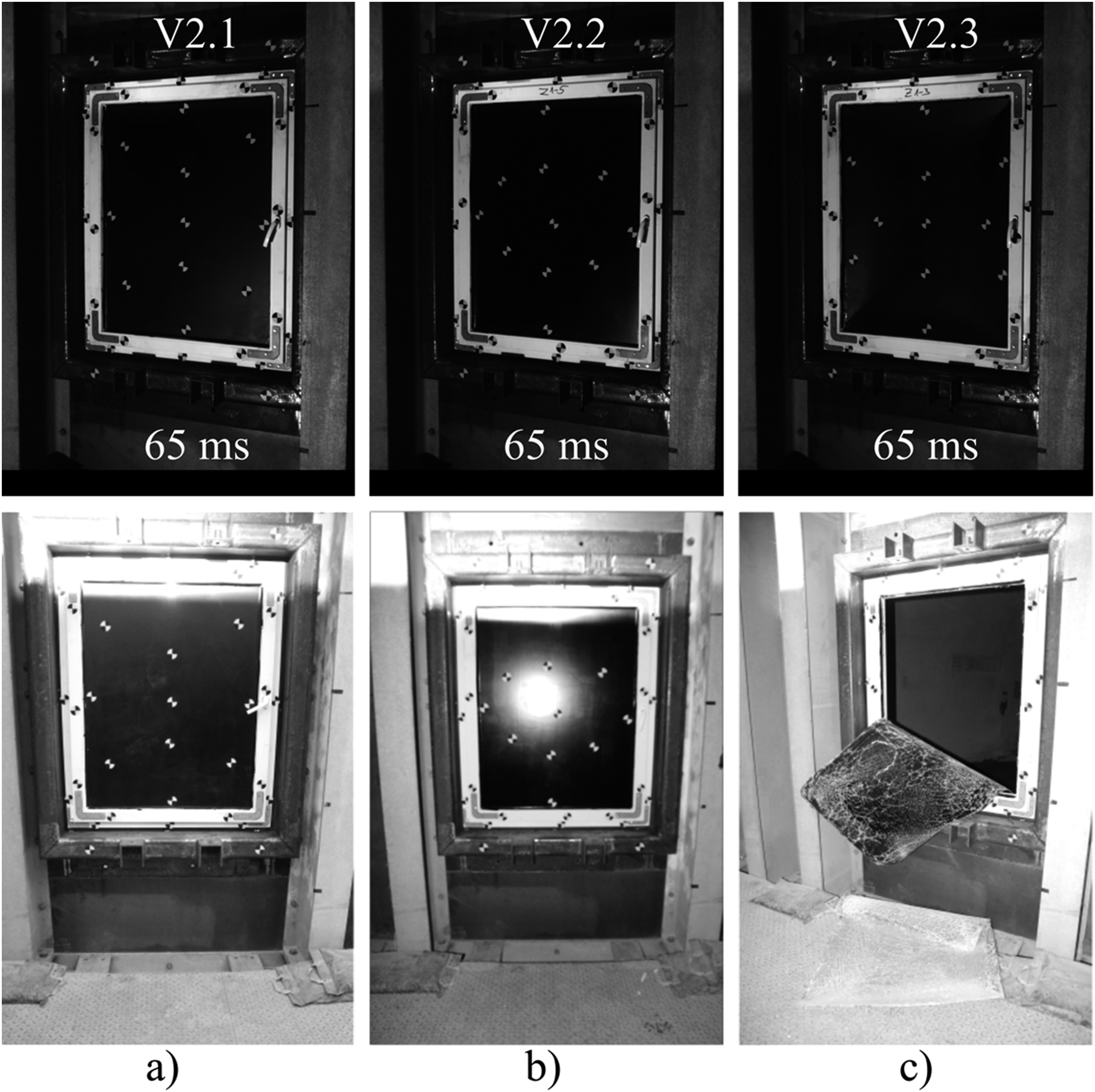
Test V2.1 and test V2.2 proved the effectiveness of the retrofit measures applied. Throughout both shock-tube tests, the sash still remained attached to the frame and the glazing remained attached to the sash frame (Figure 13(a) and (b)). In test V2.1 the glazing shattered under the effect of the secondary shock, while in test V2.2 the glazing was undamaged throughout the entire test. In summary,
In contrast to these positive results, a significantly lower level of protection was achieved in test V2.3 (Figure 13(c)). In this test, the glazing shattered during the primary shock after 14 ms. Although the anti-shatter films (ASFs) remained attached to the sash frame throughout the entire primary shock, the secondary shock finally caused the ASFs to be torn off after about 106 ms. The detached ASF came to rest in front of the window sill (Figure 13(c)). Smaller glass fragments were detached from the ASF and propelled into the protective area. Test V2.3 resulted in
In summary, the tests demonstrated the effectiveness of the adehesive bonded and bolted GFRP-patches. To illustrate the protective effect, Figure 14shows a fractured frame corner after shock-tube test V2.1. Here, the GFRP-patch bypasses the separation crack and holds the two frame pieces together. Extensive crack widths as shown in Figure 12(c) are prevented. In this way, the GFRP-patches can prevent severe deformation of the frame and thus possible unlocking of the fitting system. Fractured frame corner secured by the GFRP-patch.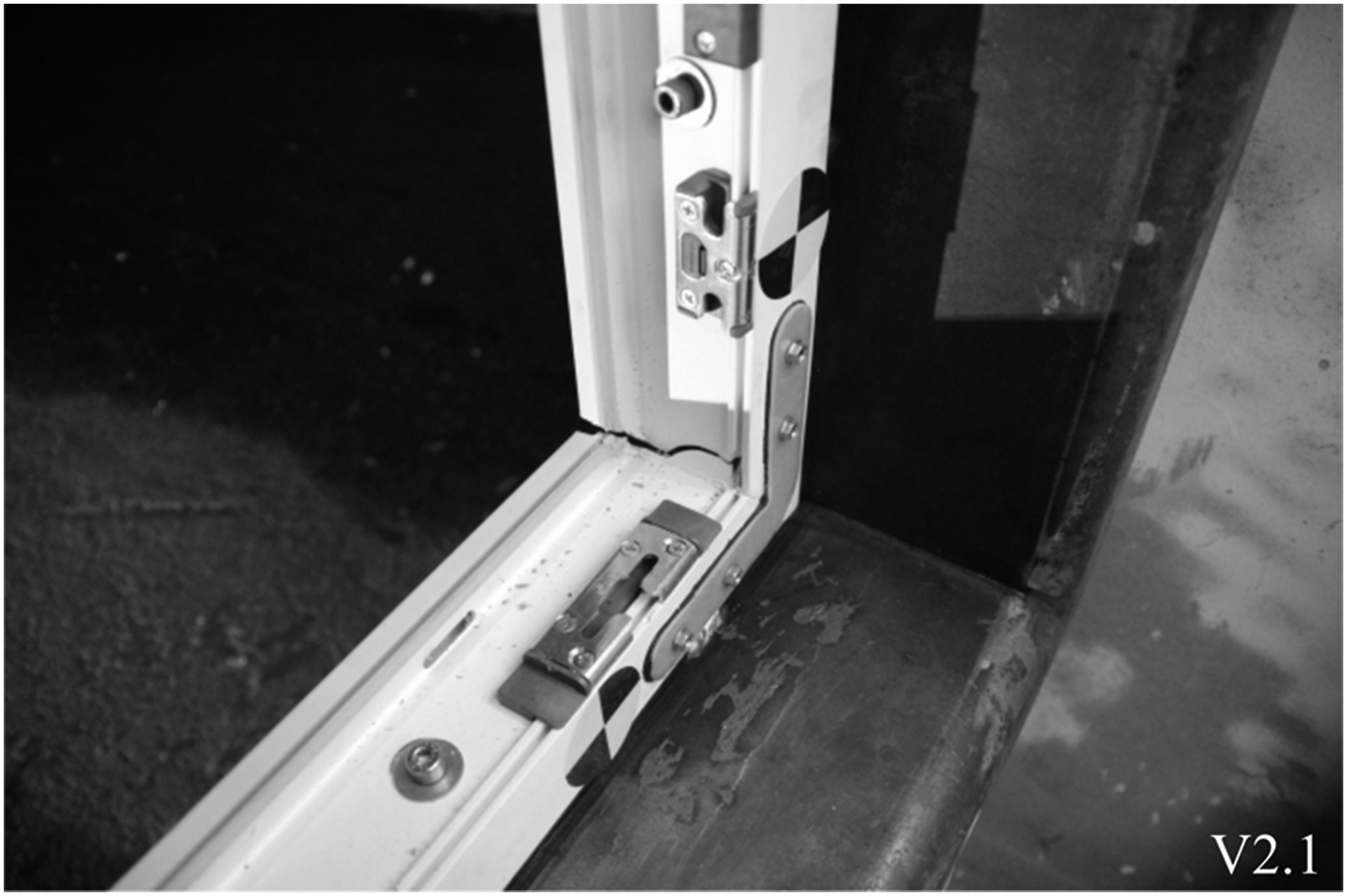
Although the ASF withstood in all three tests the primary shock, the attachment of the ASF to the window sash can be identified as a weak point during the exposure of the secondary shock. In order to increase the level of protection in these situations, there is still potential for further development in the attachment of the ASF to the sash frame, e.g., developing mechanical attachments as suggested in (Remennikov et al., 2008).
Discussion on the effectiveness of the retrofit measures
The test with configuration V0 - unprotected window - demonstrated that a conventional uPVC single casement window fails catastrophically under blast loads with a reflected peak overpressure of 37.8 kPa and a reflected maximum impulse of 190.5 kPa∙ms.
The findings for the effectiveness of each of the tested retrofit measures are summarized below.
Anti-shatter films
The hazards associated with glass fragments were successfully mitigated in all four tests (configuration V1 and V2) by installing ASFs on both sides of the IGU. Bonding the IGU to the sash frame ensured the protective effect of the ASFs. This was done by injecting an adhesive into the glazing rebate between the spacer of the glazing and the sash frame. In all four tests the ASF remained attached to the sash frame throughout the primary shock, in three of the four tests the ASF remained also attached to the sash frame during the secondary shock. Future quasi-static tests may clarify measures to increase the resistance of enhanced attachment systems.
It should be stressed that the use of ASFs does not contribute to the load-bearing capacity of the remaining components of a window. The window frames, the fittings, or the anchors in the wall opening can still fail. Therefore, without additional protective measures, there is a residual risk that the entire window sash will be thrown into the protected area.
Attaching the glazing beads
The retrofit measure of attaching the glazing beads to the sash frame with self-tapping screws proved to be effective. In none of the four tests the glazing beads were torn off from the sash frame. In the test with an unprotected window such failure mode was observed.
Burglar-resistant fitting system
The installation of a burglar-resistant fitting system resulted in a robust connection of the window sash to the frame. This possible retrofit measure can be implemented with relatively low effort by installing security strike plates and mushroom head pins.
Reinforcing the frame corners
Throughout the tests, it was observed that the window frames deform mainly by torsion about their longitudinal axis, which, when overloaded, results in smooth separation cracks along the joint surfaces of the window frames. Generally, if the frame corners are fractured, the stability of the frame can be lost. As a result, large deformations are possible, which can lead to failure of the fitting system and, consequently, detachment of the window sash from the frame.
In all configurations tested, thin metallic sash reinforcements were attached to the glass rebate of the sash frame. This provides a minimum level of restraint in the event of frame corner fracture. Crack widths in the corners of the sash frame can be limited, thus reducing deformation. Nevertheless, in configuration V1 the frame (the stationary part of the window) was not equipped with thin metallic sash reinforcements. Here, separation cracks with remarkably large crack widths occurred. This caused the failure of the fitting system and the detachment of the windows sash during the secondary shock.
All eight frame corners of Configuration V2 were equipped with GFRP-patches that were adhesive bonded and bolted to the uPVC frame. Three shock-tube tests confirmed that the external patches enabled a robust connection between the fractured frame pieces. The patch bypassed the separation cracks. In three tests, the detachment of the windows sash during the secondary shock was successfully prevented.
Summary of the performance conditions
Figure 15 summarizes the determined performance conditions for the tested configurations. Performance conditions for the configurations V0, V1, and V2.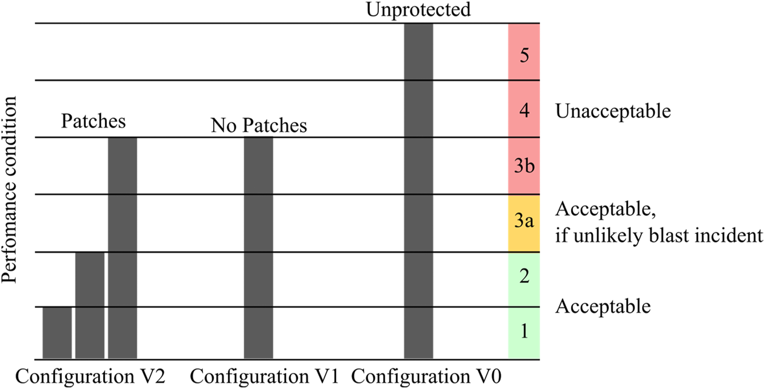
The unprotected window (Configuration V0) posed an unacceptably high level of hazard. The glazing shattered within the first 25 ms of the blast exposure, which suggests that the damage was caused by the primary shock. The cloud of glass fragments was propelled on to the witness panels, arranged at a distance of 3.0 m from the window. The performance condition is 5 (Figure 15), which is unacceptable according to the UNDSS hazard acceptability (Figure 8).
Note that due to the limited number of tests performed with configuration V0, no statistical assessment can be made regarding the repeatability or variability of the results. However, the observed catastrophic failure vividly illustrates the vulnerability of conventional windows at the blast load intensity tested. (pr = 37.8 kPa and ir = 190.5 kPa∙ms). The test result indicated that blast protection measures are necessary to ensure safety.
A slightly higher level of protection was achieved by the retrofitted Configuration V1. In this configuration, all tested retrofit measures were installed, except the GFRP-patches. As the window sash has been torn off in this test and fell about 2.4 m into the protected area, the retrofitted window is rated with the performance condition 3b (Figure 15). Since also just one test was performed with configuration V2, conducting further tests with a larger sample size could provide more comprehensive insights into its performance under blast loads.
It is important to stress that the failure of the retrofitted Configuration V1 occurred during the effect of the secondary shock, a typical phenomenon well known for shock-tube tests. In the conducted shock-tube tests, the secondary shock had a reflected impulse that is in the same order of magnitude as the reflected impulse of the primary shock. From the high-speed videos, however, it was observed that the retrofitted configuration V1 was able to withstand the effect of the primary shock. This indicates that the window may perform better in a free-field blast test, and in real blast scenarios, respectively. Note that secondary shocks can also occur in urban blast scenarios (Smith and Rose, 2006), but the magnitude is usually much less pronounced than in shock-tube tests.
The highest level of protection was achieved with configuration V2 that was equipped with GFRP-patches. The average achieved performance condition 3a is acceptable according to the requirements of the UN Department of Safety and Security (Figure 15). In all three tests the patches successfully prevented the failure of the fitting system during the secondary shock, by preventing large frame deformations at the cracked frame corners. While this performance is promising, the detachment of the ASF in one of the three tests indicated the need for further development of the attachment mechanism of the ASF to the sash frame.
In particular, three tests were conducted for configuration V2. This number is in line with the requirements of EN 13541:2012 for the certification of blast resistant glazing.
Temperature considerations
It is well known, that temperature can play a crucial role, specifically for polymers which can exhibit a pronounced temperature dependence of their mechanical properties (Bergstrom, 2015). The mechanical properties are usually considered separately for the temperature range below and above the glass transition temperature. Temperatures near or above the glass transition temperature can cause softening. Polymers typically become brittle and stiff at low temperatures.
The measured average surface temperature during the conducted tests was about 7°C. The glass transition temperature of the involved polymers uPVC, GFRP, and PET as well as the adhesive is at least 50°C higher than the prevailing temperature. From this, it can generally be assumed that the test temperature has little influence on the material behavior.
From this starting point future material tests of the applied retrofit measures should be conducted to reveal the material behavior at higher and lower temperatures, e.g., in the typical service temperature of uPVC windows between −20°C and +50°C.
Cost-effectiveness, durability, and invasiveness of the tested retrofits
Generally, the functionality of the window is not affected by the applied retrofit measures, allowing it to be opened and closed as usual. This can be an advantage over retrofit systems such as catcher-cables, which usually block the opening mechanism of the window. Moreover, the costs for retrofitting a window are comparably lower than for replacing it with a blast resistant security window.
One area that remains largely unresolved is the durability of the retrofit measures tested here. ASF for example, can suffer from weathering, UV radiation and improper handling (Bedon and Mattei, 2021). Cormie et al. (2019) therefore describe the application of anti-shatter films as a temporary remedy.
Summary
This article addressed experimental research on the protection of conventional single casement windows with insulating glass units (double-paned), and window frames made of unplasticized polyvinyl chloride (uPVC) against blast loads. The outcomes of five blast tests conducted in an explosion-driven shock-tube were presented and discussed. Various retrofit configurations for conventional windows were examined, including the use of anti-shatter films, metallic reinforcements for the window sash, adhesive bonding of the glazing to the sash frames, and fittings to enhance the window’s burglary-resistance (class RC3). Additionally, the effectiveness of innovative patches made of fiber-reinforced polymer was assessed which are supporting the corner joints of the window frames.
The experimental study showed that the tested retrofit measures can greatly reduce the hazard from fragments of conventional uPVC-windows without any significant functional or aesthetic degradation. Sustainable and cost-effective solutions for protecting windows against blast loads were developed, as the replacement of an existing window can be avoided for the tested scenario.
Footnotes
Acknowledgements
The authors would like to thank the Federal office for infrastructure, environmental protection and services of the German armed forces (BAIUDBw), for their financial support to carry out this research work. The authors would also like to thank the Bundeswehr Technical Center for Protective and Special Technologies (WTD 52) in Germany for conducting the experiments.
Declaration of conflicting interests
The author(s) declared no potential conflicts of interest with respect to the research, authorship, and/or publication of this article.
Funding
The author(s) disclosed receipt of the following financial support for the research, authorship, and/or publication of this article: This work was supported by the Federal office for infrastructure, environmental protection and services of the German armed forces (BA 3431).