
Abstract
Reinforced concrete (RC) is commonly used for protectives structures subjected to impulse loading and in the design of such structures, knowledge gained from static load conditions is often used. However, the response of an impulse loaded structural member may be very different compared to a statically loaded one, and hence it is not for sure that the observations made at static loading are also valid when subjected to impulse loading. The aim of this study is to address this uncertainty and compare the residual capacity, in terms of strength and internal work, in RC beams subjected to a combination of impulse and static loads or static load only. The impulse load was generated using a drop weight impact in which tests of 12 beams were carried out, and the residual capacity was subsequently tested statically. In addition, six beams were subjected to static loading only as references. The beams were simply supported with a span length of 1.3 m, cross section of 0.1 × 0.1 m and 2 + 2 ϕ6 reinforcement bars of various ductility. Two sets of bars were used: regular bars and prestretched bars; the latter being cold-worked regular bars with increased yield strength but decreased ductility. The drop weight (10 kg or 20 kg) was dropped from a height of 5.0 m and a high-speed camera used to record the beams’ response. From the images obtained, Digital Image Correlation technique was used to measure deformations and crack propagation. For pure static loading and mild impact loading (10 kg) combined with static loading, beams with regular bars obtained higher internal work than beams with prestretched bars. However, for severe impact loading (20 kg) combined with static loading, the difference in internal work was negligible. Regardless of bar type, the internal work increased with increased severity of the impact loading.
Introduction
Reinforced concrete (RC) is commonly used for protective structures subjected to impulse loading. This is due to its high mass and potential high energy absorption, in which the latter is thanks to the structure’s ability to withstand large plastic deformations with remaining load capacity. In the design of such structures, knowledge gained from static loading is often used. However, the response of an impulse loaded structure may be very different compared to a statically loaded one (Magnusson et al., 2014), and hence it is not for sure that the observations made at static loading are also valid for impulse loading.
The reasons for difference in response at impulse- and static loading are due to a combination of inertia, strain rate and wave propagation effects that may appear in the former. Inertia resists the change in motion and thus provide extra resistance to the structure while strain rate effects make the material stronger, stiffer and less ductile (Bischoff and Perry, 1991; Malvar and Ross, 1998). Further, wave propagation effects, that is, the transformation of information within the loaded structure, may cause the structure to respond differently both locally and globally (Cotsovos et al., 2008; Isaac et al., 2017; Pham and Hao, 2017). Even so, it is common to base the design of impulse loaded structures on knowledge gained from static loading, for example, the bending moment capacity or plastic deformation capacity (DOD, 2008; Fortifikationsverket, 2011; Johansson and Rempling, 2016).
Generally, impulse loading is caused by the blast wave from an explosion, or an impact caused by an object striking into the structure at a given velocity. The loading characteristics of such events may differ considerably, but the structural response of the affected structure is in many ways still similar. Hence, when studying the structural response of an impulse loaded structure it is often possible to use a more simplified test set-up, consisting of a drop weight impact, rather than that necessary to simulate the blast load generated by an explosion.
The design of impulse loaded structures often relies upon large plastic deformation capacities, that is, the internal work of the structure is provided by large deformations rather than large load capacity. Hence, it is essential that the internal work assumed in the design is also relevant for the actual load case. However, since the structural response of an impulse loaded structure may be different compared to when statically loaded, the plastic deformation capacity and failure modes of the structure may also be different when subjected to impulse loading. Consequently, it is of interest to make sure that the observations obtained from static loading, regarding internal work, are also valid for dynamic loading. The ductility properties of the steel reinforcement, that is, ratio f t /f y between the ultimate strength and the yield strength, and strain ε u at ultimate strength, are important parameters to obtain large plastic deformation capacity (CEB, 1998), and thus internal work, in concrete structures.
The aim of this study is to examine how the internal work of reinforced concrete beams is affected by impulse loading and mechanical properties of reinforcement. To simplify, drop weight impact tests were used to simulate the impulse loading. Similar conceptual studies have been carried out by several researchers, for example, Saatchi et al. (2009), Fujikake et al. (2009), Ulzurrun and Zanuy (2017), Peterson and Ansell (2022), to study the dynamic structural response of concrete structures. Here, though, the impact loading was also combined with static loading applied after the impact tests, investigating the residual capacity of the damaged beams. Similar studies have been done by for example, Fujikake et al. (2006) and Adhikary et al. (2015), but there the focus has not been on the residual static capacity and the number of static follow-up tests have been limited.
Drop weight impact and static tests
Test series and test set-up
Test series.
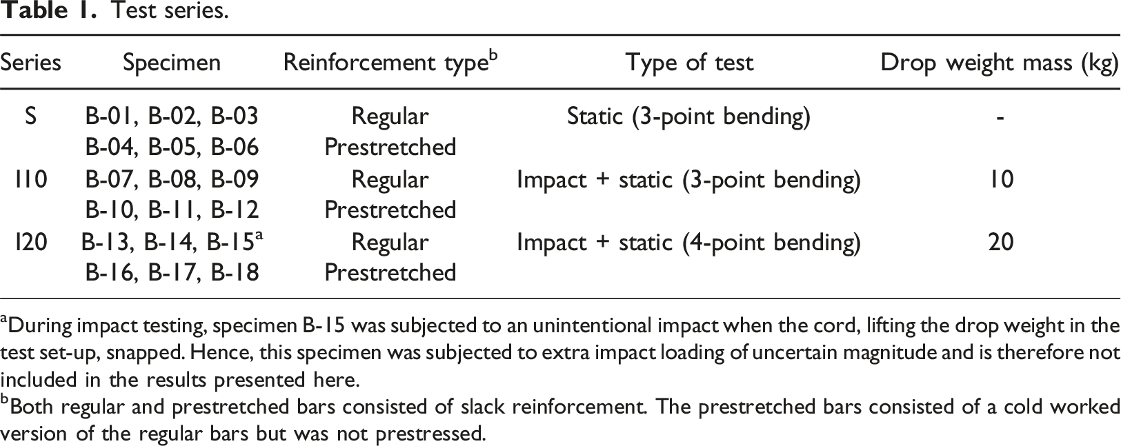
aDuring impact testing, specimen B-15 was subjected to an unintentional impact when the cord, lifting the drop weight in the test set-up, snapped. Hence, this specimen was subjected to extra impact loading of uncertain magnitude and is therefore not included in the results presented here.
bBoth regular and prestretched bars consisted of slack reinforcement. The prestretched bars consisted of a cold worked version of the regular bars but was not prestressed.
Drop weight impact tests were conducted on 12 beams and static tests on 12 + 6 beams with test set-ups according to Figure 1. The beam length was 1 400 mm with a span length of 1 300 mm, and a cross-sectional area of 100 x 100 mm. All beams were reinforced with 2 + 2 longitudinal ribbed bars of steel class K500C-T with a nominal diameter of 6 mm, located with a distance of 20 mm from the centre of the bars to the concrete surface. The beams in the impact tests were supported on fixed half-cylindrical supports with a diameter of 70 mm. The aim in these tests was to use boundary conditions that were as well defined as possible, and hence no restraint for upward movement was used. The drop weight consisted of a non-solid steel cylinder with mass 10 or 20 kg (length: 260 mm or 510 mm, diameter 80 mm, radius at contact surface 200 mm). For further details of the experiments, see Andersson and Pettersson (2019) and Leppänen (2024). Test setup for (a) drop weight impact tests, and (b) deformation controlled static tests in three-point bending (Series S and Series I10) and four-point bending (Series I20).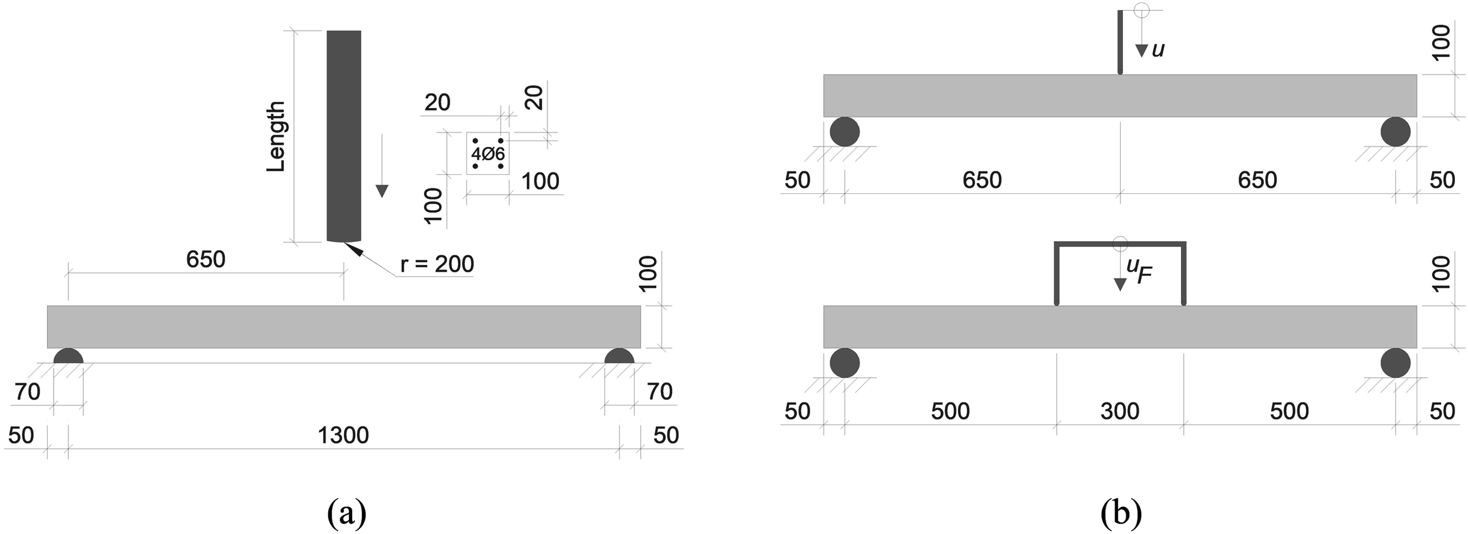
For the concrete, the compressive strength and fracture energy were tested using cubes and wedge splitting tests, respectively. The resulting average values for (recalculated) cylinder strength was f c = 41 MPa and fracture energy was G F = 113 N/m at an age of 27 days (day of impact testing) and 36 days, respectively.
For the steel reinforcement, coiled bars of class B500C-T were used. To study the influence of the reinforcement ductility, two different types of slacked reinforcement were used: one consisting of regular bars and one of what is here denoted as prestretched bars. The latter was manufactured by stretching 6.0 m long regular bars until a plastic strain ε
pl
≈ 3.0 % was obtained. Thereby, a cold worked version of the regular bars with increased proof strength f
0.2
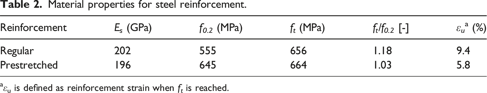
but decreased ductility was created. After stretching, the prestretched bars were unloaded and cut in lengths of about 1.38 m before being cast (without any external stress applied) into the concrete beams. Six bars of each type were tested and in Figure 2 the stress-strain curves of a representative bar of each type are compared; the average values of the mechanical properties from all bars tested are presented in Table 2. Further details of the reinforcement bars and the material tests are given in Andersson and Pettersson (2019) and Leppänen (2024). Stress-strain curve of representative reinforcement bars used in tests. Material properties for steel reinforcement. aεu is defined as reinforcement strain when f
t
is reached.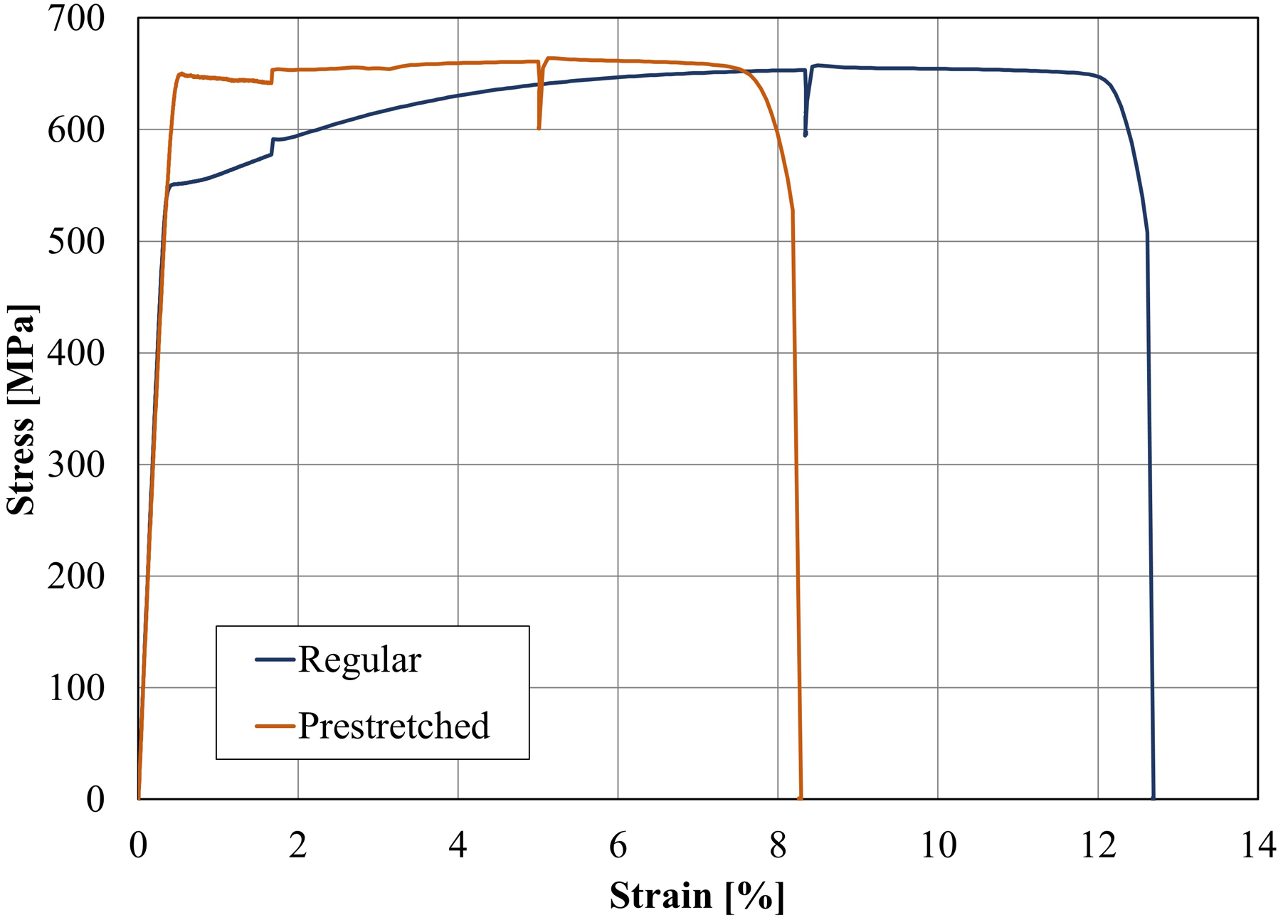
High-speed camera and DIC
The structural response of all beams was analysed using Digital Image Correlation (DIC). The basic idea behind DIC is to measure the deformation of a specimen during testing by analysing the deformation of a surface provided with a speckle pattern in a series of digital images acquired during loading. This is accomplished by tracking the position of discrete pixel subsets of the speckle pattern within the images. The deformations of the specimens are then calculated by correlating the positions and displacements of subsets in the undeformed reference image and the deformed images to produce a deformation vector field. A comprehensive description of this technique can be found in for example Sutton et al. (2009).
The impact tests of the beams were investigated using 2D-DIC technique with a Photron FASTCAM SA4 high-speed camera provided with a Tamron AF 28-75/2.8 lens, set to 50. The camera was placed at a perpendicular distance of approximately 1 980 mm from the surface of the tested beam and a camera resolution and image acquisition rate of 1024 × 400 pixels and 5 000 frames per second (FPS), respectively, were used, corresponding to a time resolution of 0.2 ms. The camera configuration corresponded to a field of view of approximately 767 x 300 mm, that is, somewhat more than half the beam length. The images from the high-speed camera were analysed by DIC technique using the software GOM Correlate (n. d). The dimensions of each subset were 15 x 15 pixels, and the subset step was five pixels, which corresponds to a subset size and data point spacing of approximately 11.3 mm and 3.8 mm, respectively.
In the static loading tests, 3D-DIC measurements with a stereoscopic camera set-up were performed with the system ARAMIS 12M by GOM Correlate (n. d). The images were captured with a frequency of 0.5 FPS and the dimensions of each subset were 17 x 17 pixels and the subset step was 14 pixels. This corresponds to a subset size and a data point spacing of approximately 4.4 mm and 3.6 mm, respectively, at the surface of the beam.
Results
Response at impact loading
The initial response of a beam subjected to impact loading may be very different compared to that obtained in a beam subjected to static loading. In Figure 3, the deformed shape at different stages of an impact loaded beam is schematically illustrated (Leppänen et al., 2020). This type of response was also obtained in the impact tests presented herein, see Figure 4. Here, the relative deformation Schematic illustration of the initial dynamic response of an impact loaded beam not vertically restrained at the supports, based on Leppänen et al. (2020). Ratio deformation/mid deflection of beam B-07 at different times after impact.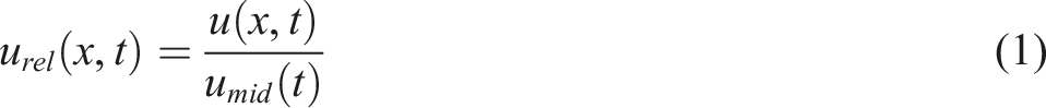
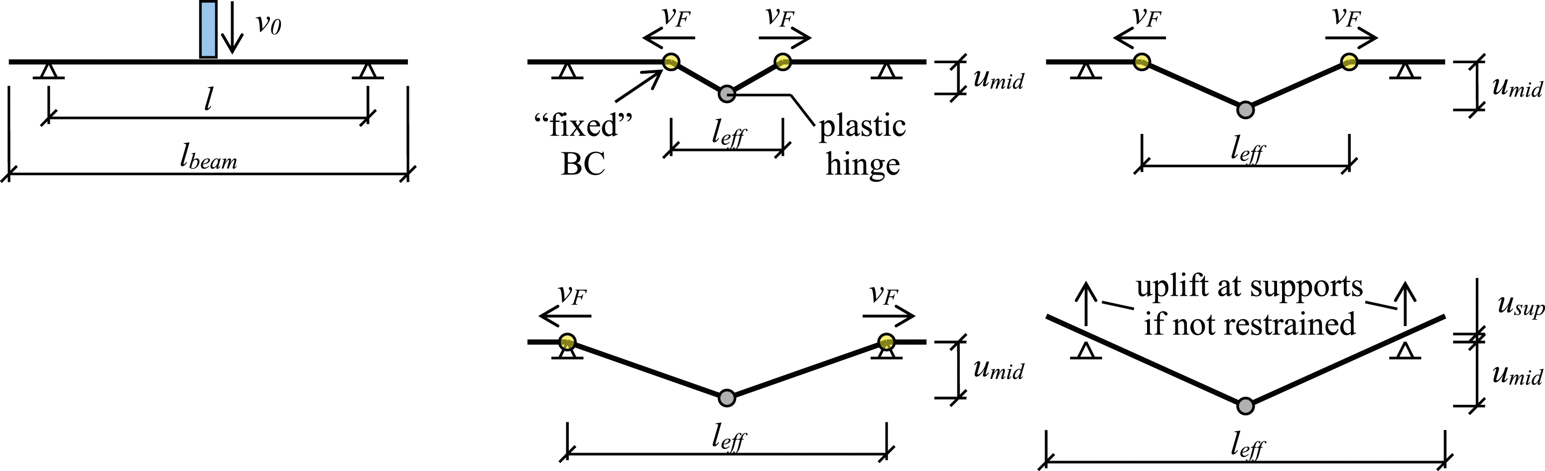
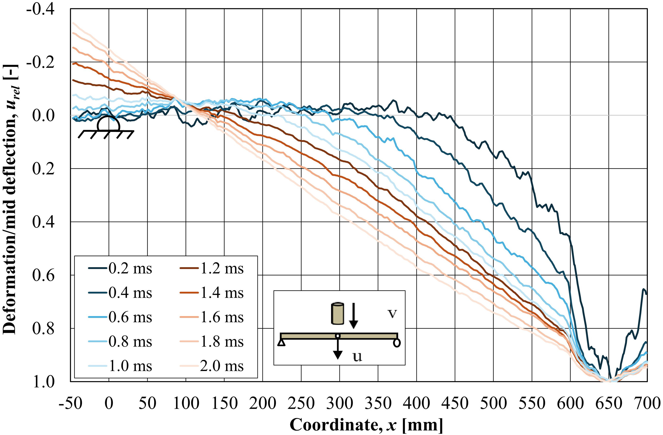
of beam B-07 is shown for the initial 2.0 ms after impact (a similar response was observed for all impact loaded beams). From this it is evident that the impact loaded beam initially does not obtain the typical triangular deformation shape expected for a statically loaded beam that exhibit a plastic hinge in the middle of the beam. Instead, the beam parts close to the supports are initially unaffected by the applied impact load, resulting in just the middle part of the beam deforming. At time t = 0.2 ms, this generates a local negative curvature next to the impact zone, approximately halfway to the support, and with time, this region with negative curvature moves towards the support. When the negative curvature reaches the support, uplift of the beam occurs since it is not vertically restrained. This phenomenon can be looked upon as the effect of time dependent boundary conditions, that is, the boundary conditions can approximately be regarded as fixed with the location of the fixity moving closer to the real support with time. Eventually, the beam becomes fully “aware” of its boundary conditions and the response then changes to something more like that of a statically loaded beam. For the beam in Figure 4 this change is completed after about 2 ms.
Using DIC, the resulting crack pattern in the beams can be indicated by showing the maximum principal strain field. In Figure 5 this is done, whereby the change in crack pattern during the initial response (t = 0.4-2.0 ms) after impact are shown for all beams subjected to impact loading. The negative curvature obtained in the beam during the first millisecond, see Figure 4, results in tensile stresses which may cause cracking in the top of the beam. For times t = 0.4-0.8 ms, such cracks are also seen in Figure 5. However, at time t = 2.0 ms, the top cracks have closed again and cracks in the bottom of the beam have developed instead. In addition to the initial response, the resulting crack pattern at u
max
is shown together with time of occurrence. Initial crack pattern of all beams subjected to impact loading (red colour = crack, blue colour = uncracked concrete).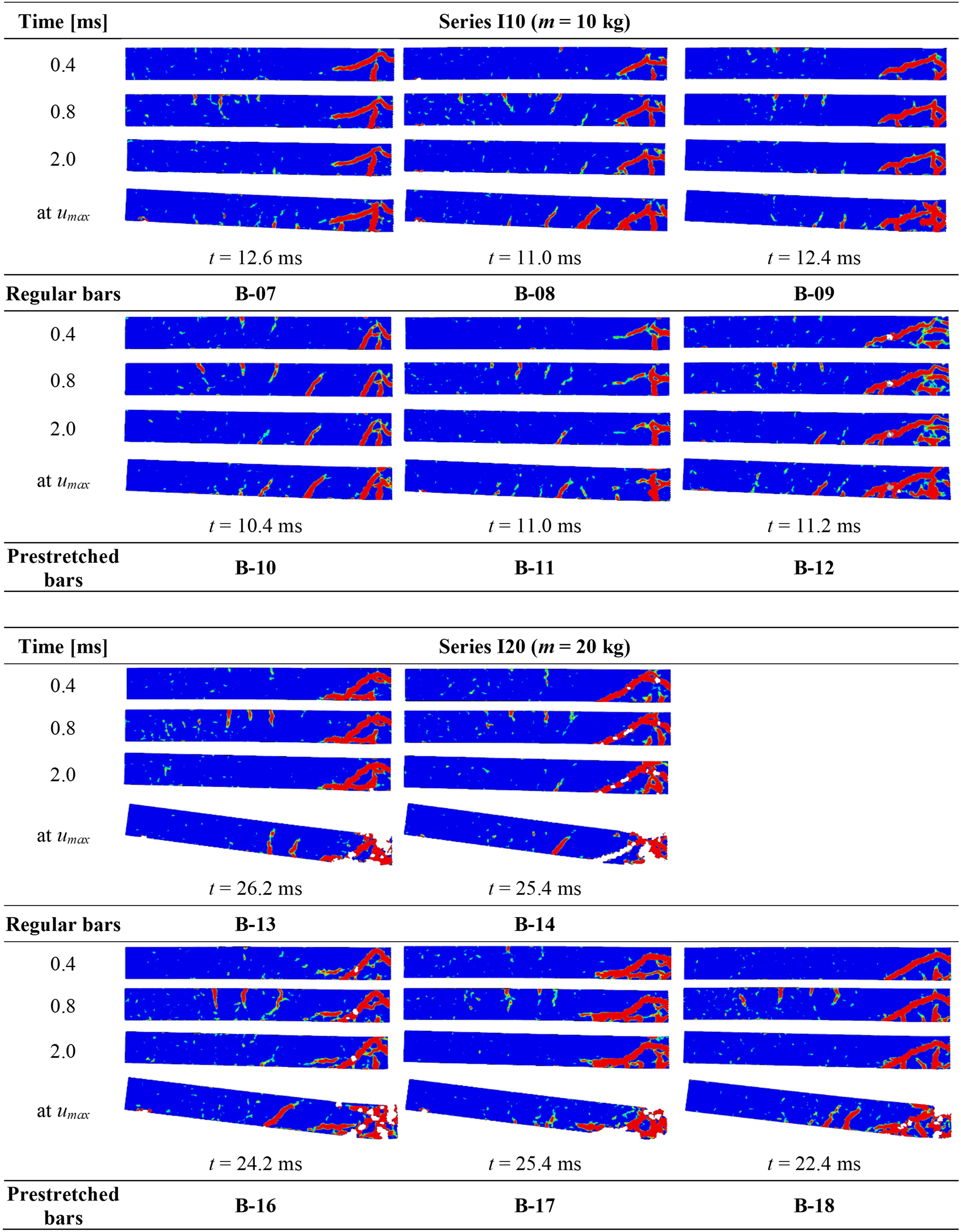
In Figure 4, it is shown that there is an initial uplift of the beam at the support. However, this uplift is only temporary, and the beam is soon pressed down in contact with the support again. In Figure 6, the uplift u
sup
(t) at the support is presented together with the midpoint deflection u
mid
(t) for beams B-07 and B-13. Further, the modified midpoint deflection over time u(t), determined as Deflection-time curves showing support uplift, midpoint deflection and modified midpoint deflection for beams B-07 and B-13 when subjected to impact loading. Summary of results from impact and static tests. u
max
= maximum deflection due to impact, u
pl
= plastic deflection due to impact, W
i,imp
= internal work of beam due to impact, u
fail
= deflection at failure at static loading, F
max
= maximum load at static loading, W
i,sta
= internal work of beam at static loading (total internal work for Series S, plastic internal work for Series I10 and I20), u
fail,tot
= u
pl
+ u
fail
= total deflection due to impact and static loading, W
i,tot
= W
i,imp
+ W
i,sta
= total internal work from impact and static loading.
In Leppänen et al. (2020), it was shown using nonlinear FE analyses, that the lack of support preventing uplift had negligible effect on both the u(t) response and the resulting crack pattern of impact loaded beams of similar geometry and load as that used in the tests presented here. Hence, it is judged that the influence of uplift did not have any major influence on the response of the tests carried out. However, the temporary uplift at the support caused the modified midpoint deflection u(t) to obtain a local leap in the curve, see Figure 6. This type of response was obtained for all the beams in the study subjected to impact loading.
In Figure 7, the modified midpoint deflection over time u(t) for the impact loaded beams are shown for all beams. The scatter of the results was generally small until the maximum deflection was reached but increased somewhat after that. Failure was not reached in any of the beams due to impact loading. It can be noted that the deflections obtained in the beams with prestretched bars were smaller than that obtained in beams with regular bars. This is an effect of beams with prestretched bars reaching a higher load capacity at a lower deflection, see more of this below in Section “Response at static loading”, which means that for the impact loads used in these tests, the beams with prestretched reinforcement were more “effective” than beams with regular reinforcement. However, it does not mean that prestretched bars generally is a better solution than using regular bars. Modified midpoint deflection-time curves from impact tests of beams with (a) regular bars, and (b) prestretched bars.
From the impact loaded tests, it was not possible to predict how close a certain beam was to final failure. To investigate this, static tests were used to determine the residual capacity of the previously impact loaded beams, i.e., the residual capacity producing internal work that could balance the increased external work from a potentially more severe impact load.
Response at static loading
The beams that were subjected to an impact load were subsequently statically loaded to evaluate their residual response, i.e., stiffness, load capacity and plastic internal work. For comparison, 3 + 3 undamaged reference beams (i.e., beams that was not previously subjected to impact loading) were tested and the response, shown as load-deflection F(u) curves, of these tests are shown in Figure 8. The maximal load, F
max
, was somewhat higher in the beams with prestretched bars than in the beams with regular bars, and this load was also obtained at less deflection of the beams. However, the maximum deflection at failure, u
fail
, was considerably higher in the beams with regular bars than in beams with prestretched bars. Consequently, this indicates that the beams with prestretched bars produce a more effective resistance against less severe impact loads; that is, impacts that only cause a deflection u
mid
of about 30 mm. For more severe impact loads, though, higher deflection will be obtained in the beam to withstand the load, and for such cases, the static response indicates that beams with regular bars would be more effective than beams with prestretched bars. Load-deflection curves (static loading in three-point bending) for reference beams (regular bars: B-01 to B-03, prestretched bars: B-04 to B-06).
In Figure 9, the residual response F(u), due to static loading, of the impact loaded beams in Series I10 are compared with the response of the corresponding reference beams in Series S. For the beams in Series I10, an initial plastic deflection already existed due to previous impact loading and in the graphs, this is indicated as an initial deflection at zero static load. The initial elastic stiffness of the impact loaded beams was very similar to that obtained in the cracked reference beams. When reaching a load level approximately corresponding to that of the load-deflection curves of the reference beams, reinforcement yielding occurred. This indicates that the initial residual response of the beams previously subjected to impact loading “tuned in” to the response of the statically loaded reference beams. This was true for all beams, regardless of type of bar used. In the beams with regular bars, though, the residual response showed an almost constant load plateau with substantially increased deflection at final failure (about 30-40 mm) compared to that obtained in the reference beams, see Figure 9(a). However, for the beams with prestretched bars, the residual response was more similar to that of the reference beams, even though the deflection at final failure increased (about 10-15 mm) here as well, see Figure 9(b). Final failure was in all these beams obtained due to reinforcement rupture. From Figure 9 it can be concluded that in these tests, previous impact loading had a positive effect on the residual response of the beams: the load capacity at a given deflection was similar or higher than in the reference beams, while the deflection u
fail
increased significantly (some) for beams with regular bars (prestretched bars). This indicates that there is a beneficial effect to the beam’s structural response when subjected to impact loading compared to static loading. Comparison of load-deflection curves (static loading in three-point bending) for reference beams and beams first subjected to drop weight impact of mass 10 kg (Series I10): (a) regular bars, and (b) prestretched bars.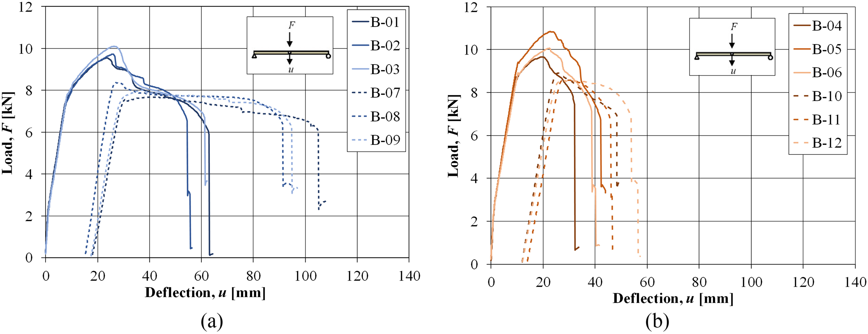
In Figure 10, the residual response F(u), due to static loading, of the impact loaded beams in Series I20 are shown. When subjected to impact loading, these beams obtained large plastic deformations, and because of this, considerable concrete damage also developed in the mid part of the beam. This damage made it unsuitable to apply a point load in the middle of the beam, and instead four-point loading was used as shown in Figure 1(b). The different test set-ups used make a direct comparison with the reference beams difficult and here only a comparison of the residual response with regular and prestretched bars are made. In the beams with the regular bars, the residual response was very similar; both initial stiffness, maximum load, and total deflection at final failure. In the beams with prestretched bars, larger deviations in the response were obtained; however, the final failure was obtained at almost the same total deflection. Final failure was in beams B-16 and B-18 due to reinforcement rupture of at least one bar. However, in beams B-13, B14 and B-17, considerable load decrease was obtained due to a combination of large diagonal shear cracks and partial loss of the concrete compressive zone, resulting in a weak residual response at increased deflection, without reaching a distinct failure. The tests of these beams were instead stopped when the load capacity had decreased to about 2 kN. Load-deflection curves (static loading in four-point bending) for beams first subjected to drop weight impact of mass 20 kg (Series I20) (initial deflection when F = 0 kN shows plastic deflection u
mid
from impact loading).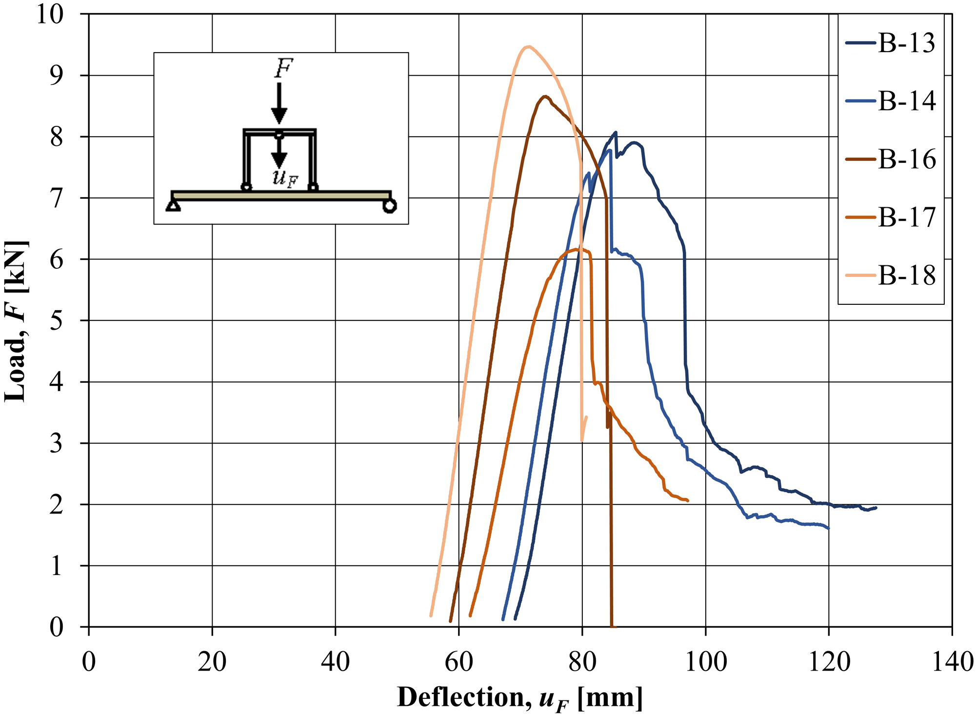
Crack patterns from all the static tests are shown in Figure 11. For Series S and I10, the crack pattern shown are given at a deflection u
mid
= 30 mm (load level F
30mm
listed in table) for the corresponding test. For Series I20, though, the crack pattern shown is given for a deflection when load F
max
was obtained in the residual static tests (deflection u
Fmax
listed in table). White regions in the crack pattern indicate loss of data due to spalling of the concrete cover, thus losing the speckle pattern on the concrete surface used in DIC. Crack patterns obtained in static tests (red colour = crack, blue colour = uncracked concrete).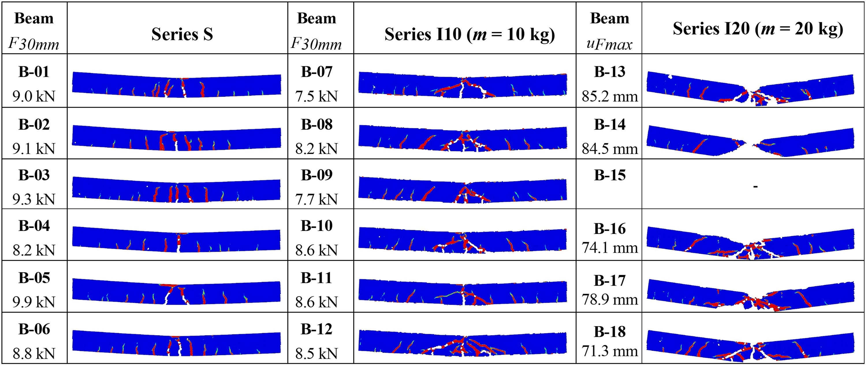
For the statically loaded reference beams (Series S), typical vertical flexural cracks can be observed in Figure 11. For the beams previously subjected to impact loading (Series I10 and I20), though, diagonal shear cracks are seen in the middle of the beam originating from the point of impact and the flexural cracks generally have a more skewed shape. This is because the crack patterns observed were originally created during the impact loading and during the following static loading the existing cracks re-opened again and continued to grow. Hence, for these beams, the crack pattern obtained by static loading is very similar to that obtained from the impact loading, compare with crack patterns at u max in Figure 5.
Summary of results
In Table 3, some key results from the impact and static tests are summarised. Apart from modified deflections u and maximum static load F max , also the internal work W i (i.e., the energy absorption) is listed in the table. In the static tests, W i,sta 1 was determined as the area under the F(u) curves in Figures 8 to 10. For Series S, this was done for the full F(u) curve up to a deflection u corresponding to when the post-peak load capacity had reached a load capacity F = F max /2 ≈ 5 kN 2 . Consequently, the contribution to the internal work W i,sta beyond this deflection was neglected. For Series I10 and I20, a similar concept was used for the static loading, but here the elastic part of the F(u) curve (i.e., up to the deflection at which reinforcement yielding was obtained) was not included in W i,sta . This elastic contribution to the total internal work was not accounted for since it is already included in the internal work W i,imp made when the beam was subjected to impact loading.
To estimate the internal work during impact loading, the same method as for static loading cannot be used. Instead, a simplified method based on energy equilibrium, theory of plastic impact and an equivalent single degree of freedom system (SDOF) as described in for example, Johansson and Laine (2012), was used to estimate the internal work W i,imp .
The kinetic energy of the drop weight just prior to impact can be determined as
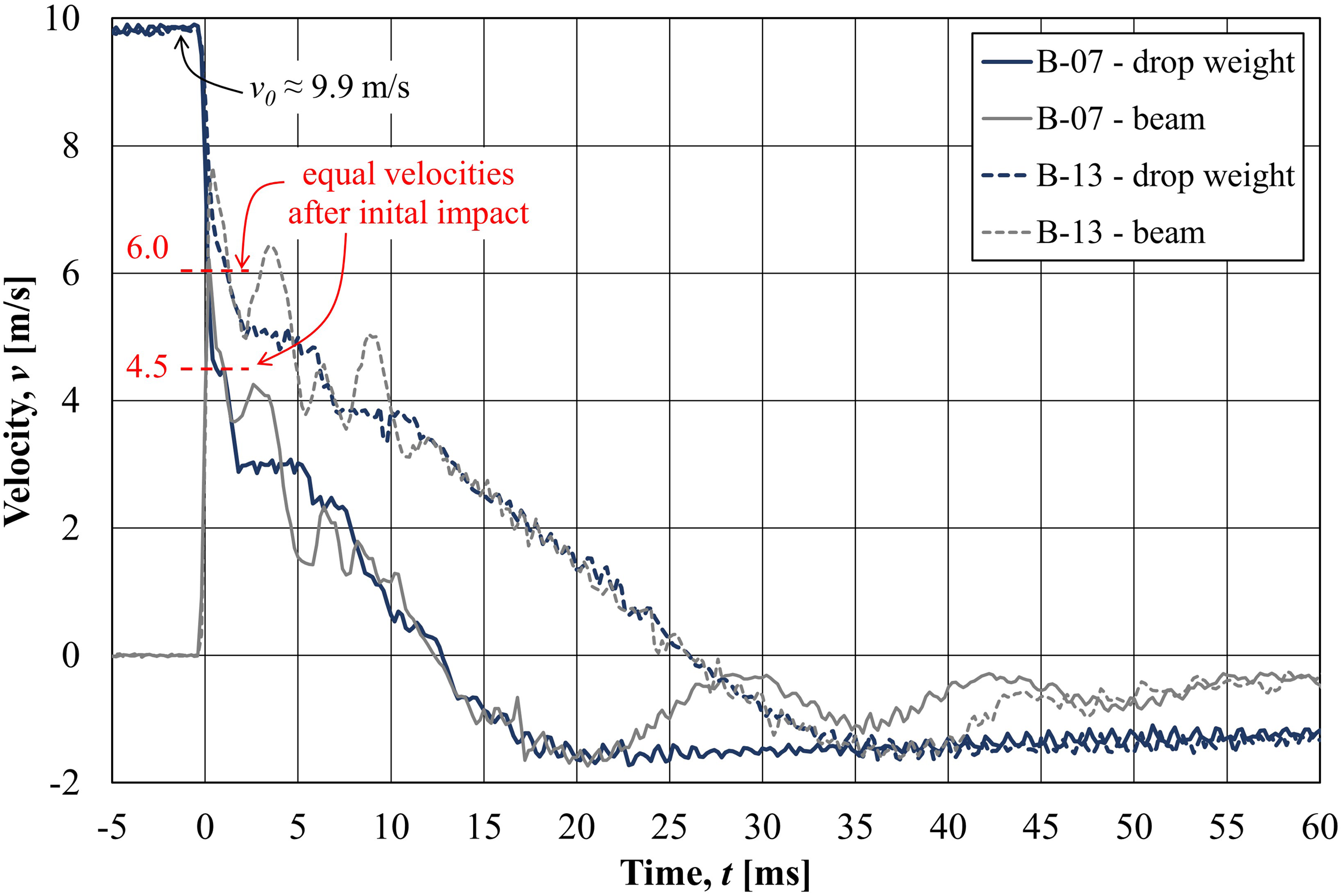
In Figure 12, the velocities of the drop weight and beam midpoint (i.e., point of impact in beam) are shown for beams B-07 and B-13. From this, it can be seen that there are some variations in the velocities in the initial impact stage; for both tests there are at least three local impacts during the first 10 ms. However, the average velocities of drop weight and beam were similar in both tests until the beam rebounded, that is, after maximum deflection was obtained. This indicates that the assumption of plastic impact between drop weight and beam is reasonable. Therefore, plastic impact between the drop weight (mass m
w
) and beam (mass m
b
) was assumed and using conservation of momentum, the joint velocity v
wb
of the mass and beam midpoint after impact can be expressed as Velocities of drop weight and beam for beams B-07 and B13.
Here, m
b
= κ
LM
· m
beam
is the effective mass of the beam, in which κ
LM
is a load-mass factor used to transform the beam to an equivalent SDOF system, see for example Biggs (1964). For the actual load case, a plastic response of the beam was obtained, giving κ
LM
= 0.333, which together with m
beam
= 32.5 kg for the 1.3 m long beam part between the supports, gives m
b
= 10.8 kg. Using equation (4), the velocity after impact may be estimated as 4.8 m/s (6.4 m/s) för beams in Series I10 (I20). These estimates may also be compared with the velocities obtained after the first impact of beam B-07 (B-13) which were about 4.5 m/s (6.0 m/s), see Figure 12. Hence, even though clearly not an ideal plastic impact, this assumption is still deemed to be sufficient for the purpose of estimating the internal work obtained in the beams due to impact loading.


In Figure 13, the total internal work W
i,tot
in Table 3 are compared. For Series S it can be concluded that the reinforcement ductility had high influence on W
i,tot
when the beam was subjected to static loading only; here W
i,tot
was in average a factor 1.51 higher when using regular bars compared to when using prestretched bars. This is also well in line with previous experience from static loading (CEB, 1998) and thus as expected. For beams in Series I10 it can be concluded that W
i,tot
increased compared with that obtained in static loading only, but that the difference obtained due to reinforcement ductility remained similar to a factor 1.49. Comparison of total internal work.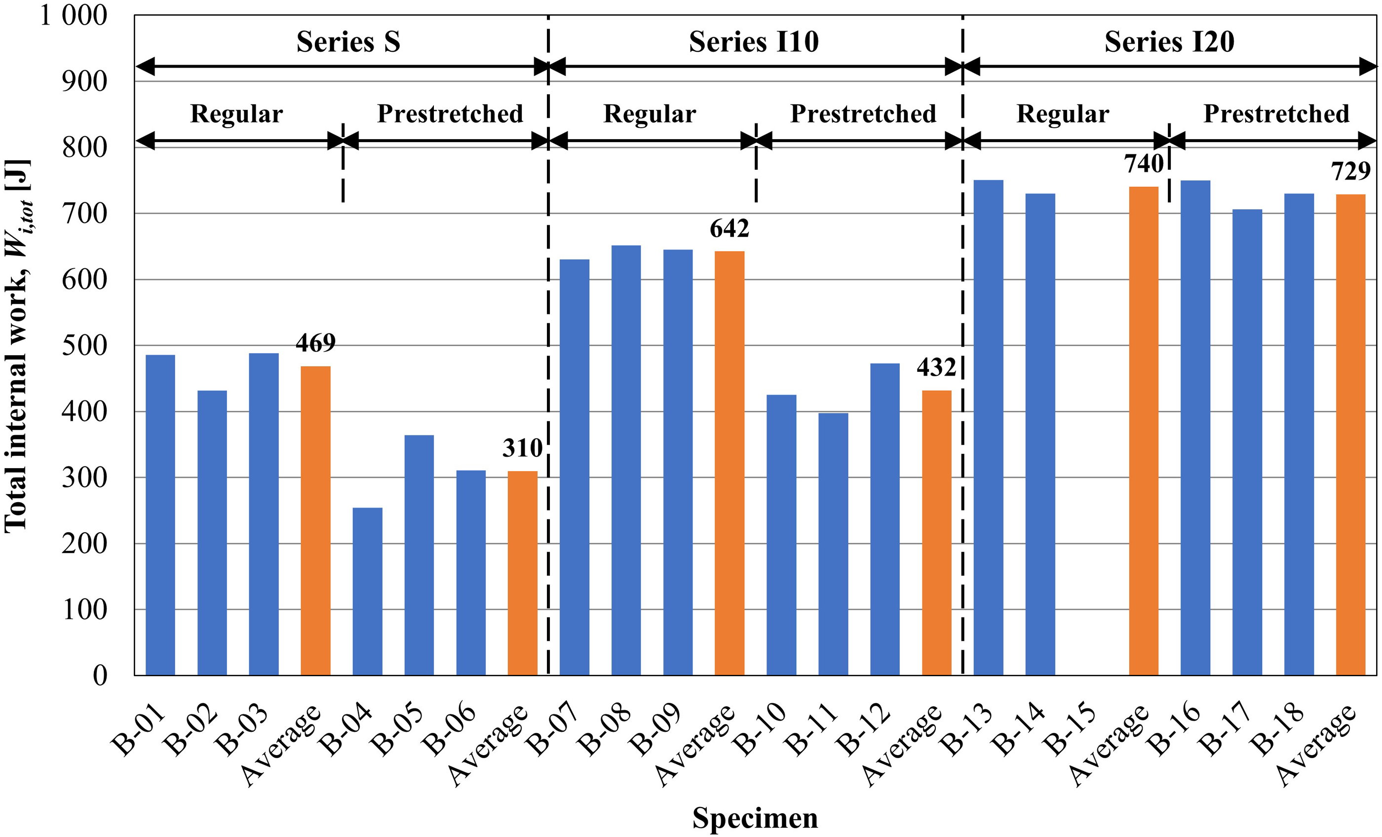
However, for beams in Series I20, there was still an increase in W i,tot compared to Series S and I10 but the difference in W i,tot due to reinforcement ductility was negligible. That is, for these beams, in which the impact loading caused severe damage, there was insignificant difference of whether using regular bars or less ductile prestretched bars. Consequently, this response differs much to that observed in beams subjected to static load only. It also further indicates that the structural response obtained at impact loading may differ much compared to that of static loading. In all tests carried out here, though, the response obtained was improved due to impact loading; that is, the internal work increased with increased impact loading. In average, W i,tot increased with a factor 1.37 (1.39) and 1.58 (2.35) in Series I10 and Series I20, respectively, in beams with regular (prestretched) bars. Consequently, it would have been conservative to use guidelines based on static loading for the estimation of internal work when designing the impact loaded beams studied here.
It is believed that the increased plastic deflection, and hence the internal work, obtained in beams first subjected to impact loading, was mainly due to positive effects related to the appearance of diagonal shear cracks close to the impact zone. Thereby, the bond between reinforcement and concrete was weakened in this region, which meant that a larger part of the reinforcement could reach yielding prior to final failure. Consequently, the length of the plastic hinge increased, which resulted in larger plastic deflections and thus also increased internal work.
However, this hypothesis does not explain why there was negligible difference in W i,tot for beams in Series I20 when using regular or prestretched bars. In beams with regular bars (beams B-13 and B-14), though, the load capacity at large deflection was limited by concrete crushing in the compressive zone, and hence the contribution to W i,sta , due to still intact reinforcement, was small. Consequently, it is believed that if concrete crushing in these beams could have been further postponed (e.g., by using stronger concrete), regular bars would also have resulted in an increased amount of total internal work W i,tot .
Conclusions
The aim of this study was to examine the effect of various ductility of reinforcement bars used in concrete beams subjected to impact loading. Impact tests, using a steel drop weight with mass 10 kg or 20 kg and a drop height of 5.0 m, were carried out. To examine the residual response after impact loading, the beams were subjected to static loading until failure and from this, the total internal work in the beams was determined.
The following conclusions can be drawn: • In all cases, previous impact loading had a positive effect on the residual response of the beams studied; that is, the internal work of the beams increased with increased impact loading. • For pure static loading, and combination of mild impact loading (mass 10 kg) and static loading, the total internal work was about 50 % higher in beams with regular bars compared to beams with less ductile prestretched bars. • For beams first subjected to severe impact loading (mass 20 kg), the total internal work increased further but the effect of various reinforcement ductility was negligible. However, it is believed that if concrete crushing in the compressive zone could have been further postponed, for example, by increasing the concrete strength, the beams with regular bars would have resulted in higher increased total internal work than the beams with prestretched bars. • The response observed for beams subjected to severe impact loading differs from that obtained in static loading and is a further proof that the structural response obtained at impact loading may differ much compared to that obtained at static loading. Still, it can be concluded that it would have been conservative to use guidelines based on static loading for the estimation of internal work when designing the impact loaded beams studied here. • High-speed camera in combination with Digital Image Correlation (DIC) analysis has proved to be a powerful tool for studying the structural response of impact loaded concrete beams where it can be used to study for example, crack propagation and deformations. An additional advantage with DIC is that the parameters that are of interest do not need to be known or specified beforehand, that is, if images of acceptable resolution are available it is possible to determine what type of results are of interest at a later stage. Compared to conventional measuring techniques, this is a considerable advantage.
Footnotes
Acknowledgements
This research has been carried out at Chalmers University of Technology and the authors would like to thank the financier’s representative Lars Gråbergs (BSc), from the Swedish Civil Contingencies Agency (MSB). Thanks also to research engineer Sebastian Almfeldt (M.Sc.), Chalmers, responsible for carrying out the experiments, and Mathias Flansbjer (PhD), Rise, responsible for the high-speed camera and help with DIC. Additionally, Leo Laine (PhD), member of the West Coast Sweden Shock Wave Group, is highly acknowledged for his support.
Declaration of conflicting interests
The author(s) declared no potential conflicts of interest with respect to the research, authorship, and/or publication of this article.
Funding
The author(s) disclosed receipt of the following financial support for the research, authorship, and/or publication of this article: This work was supported by the Swedish Civil Contingencies Agency (MSB). Additional funding for the experiments was provided by Fortifikationskårens forskningsfond (Fortification corps’ research fund).