
Abstract
This paper is focused on the study of innovative bi-stable supports to improve the impact performance of point-fixed glass panels, for typical use in facades. To mitigate the effects of impact and reduce potential risk for people, the introduction of innovative, bi-stable, mitigation devices between the fixing system and the primary building structure is addressed. The proposed dissipative system is able to control and minimise the input force which is transmitted to the primary building, controlling the damage around the supports and preventing the detachment of the glass panels. Based on LS-Dyna Finite-Element (FE) models, the proposed protection system is designed to have a snap-through behaviour under impact. The performance of the system is quantified for two different glazing systems, which are numerically investigated under various impact configurations.
Keywords
Introduction
Whether applied in wide glazing facades or in simple traditional windows, glass material is rather ubiquitous in buildings Feldmann et al. (2014). Being associated with a multitude of aspects mostly related to transparency and light, glass is widely used in civil engineering structures. Due to their mostly brittle tensile behaviour and limited resistance, however, glass components are known to require specific design and detailing to improve their performance towards prescribed design loads Feldmann et al. (2014); Amarante dos Santos et al. (2020). In this regard, the use of laminated glass sections, which greatly improves the post-breaking resistance, is a basic and efficient mitigation strategy for several loading conditions Pelfrene (2016). In case of extreme events like impacts, however, the vulnerability of glazing systems is particularly high Schneider and Schula (2016); Biolzi et al. (2018); Parra et al. (2019); Kozlowski (2019); Bez et al. (2021). Under ball drop and pendulum impact, so far, literature studies confirmed the critical role of various glass components for constructional applications, like simple panels Van Dam et al. (2019); Reich and Raghu Sagar Vanapalli (2018); Wang et al. (2018); Kozłowski et al. (2021); Huang et al. (2023), full-scale columns Bedon et al. (2017) or traditional in-service windows derived from old residential buildings Figuli et al. (2021). Even more attention is required for point-fixed glass components, where further stringent protection measures are recommended to avoid premature damage in the region of restraints. So far, the use of innovative devices and restraints, towards the definition of so-called adaptive systems Bedon et al. (2019), proved that the structural response of variably loaded and restrained glass components in buildings can be strongly mitigated. Literature examples can be found for seismic events and explosions Santos et al. (2016), multi- hazard Bedon and Amadio (2018) or even wind pressure Santos et al. (2014).
The energy absorption capabilities of a novel types of structures that arose with the advent of additive manufacturing has been studied by several authors Debeau et al. (2018); Chen et al. (2021); Ma et al. (2023). One of this novel structures, the negative stiffness honeycomb, is able to elastically absorb energy, recover their initial configuration and absorbs mechanical energy repeatably. Unlike their traditional counterparts, negative stiffness honeycombs are able to buckle elastically when the compressive loading surpasses the design threshold and, consequently, the resulting deformation is recoverable. The authors Debeau et al. (2018); Chen et al. (2021) reported significant improvements in both energy absorption and shock isolation when compared with regular honeycombs. Alternatively, auxetic multistable mechanical metamaterials have been reported in the literature Ma et al. (2023). Similarly to the negative stiffness honeycombs, this novel structure is reusable and can dissipate energy multiple times due to its elastic energy absorption. Ma and team concluded that, as developed, the proposed structure presents an auxetic behaviour that may improve shear, impact and fracture resistance, which indicate potential in the fields of shock isolation and energy absorption.
In order to mitigate impact in point-fixed glass systems, this paper explores the introduction of protection devices between the traditional fixing system itself and the primary building structure. These devices are specifically designed to absorb the kinetic energy of the impactor and control the input force which is transmitted through the supports to the primary structure. To this aim, a newly designed device for point-fixed glazing systems is presented and analysed, with the help of Finite-Element (FE) models. The proposed system represents a three-dimensional (3D) version of a Von-Mises planar truss, exhibiting a snap-through behaviour, with an additional restitution element that provides the bias force to rearm the system. After the complete mechanical characterisation of the proposed device, the behaviour of two different glazing systems under impact is analysed, based on parametric non-linear dynamic simulations, to quantify the benefits of such protection system.
Materials and methods
The present paper resorts to parametric FE numerical simulations to evaluate the applicability of a protective solution for point-glass fixings, especially used to enhance the performance of glass panels subjected to impacts. The explicit FE code LS-DYNA Livermore Software Technology Corporation (2018), which considers both material and geometric non-linearity, was used to simulate various impact configurations on glass facade components.
Development of the bi-stable tripod
The present study proposes a novel protective solution inspired on the planar Von-Mises truss, which is a simple bi-stable structure composed of two simply supported bars and a central hinge. In order to prevent out-of-plane buckling of the truss, an additional bar is added into the system, transforming it into a three-dimensional tripod, also featuring a bi-stable behaviour. Although bi-stable structures are known to be good candidates for applications that require energy absorption, they usually lack the ability to reposition the system, once the mechanical loading is removed. In order to provide the system with this re-centring ability, an additional bias spring is added to the original tripod, resulting in the protective solution shown in Figure 1, shown together with the glass point-fixing apparatus. 3D conceptual model of the proposed protective solution.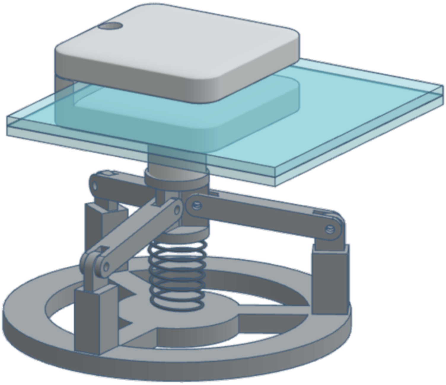
Analytical model In order to derive the analytical model for the planar Von-Mises truss it is assumed that the system is composed by two elastic bars with length L0, cross-sectional area A and Young’s Modulus E. As illustrated in Figure 2a, the bars, initially at an angle α, are subjected to a concentrated load P. Bazant and Cedolin (2010) state that the equilibrium path of the structural system, as depicted in Figure 2(b), is given by Planar Von-Mises truss. (a) Geometry (b) Equilibrium path.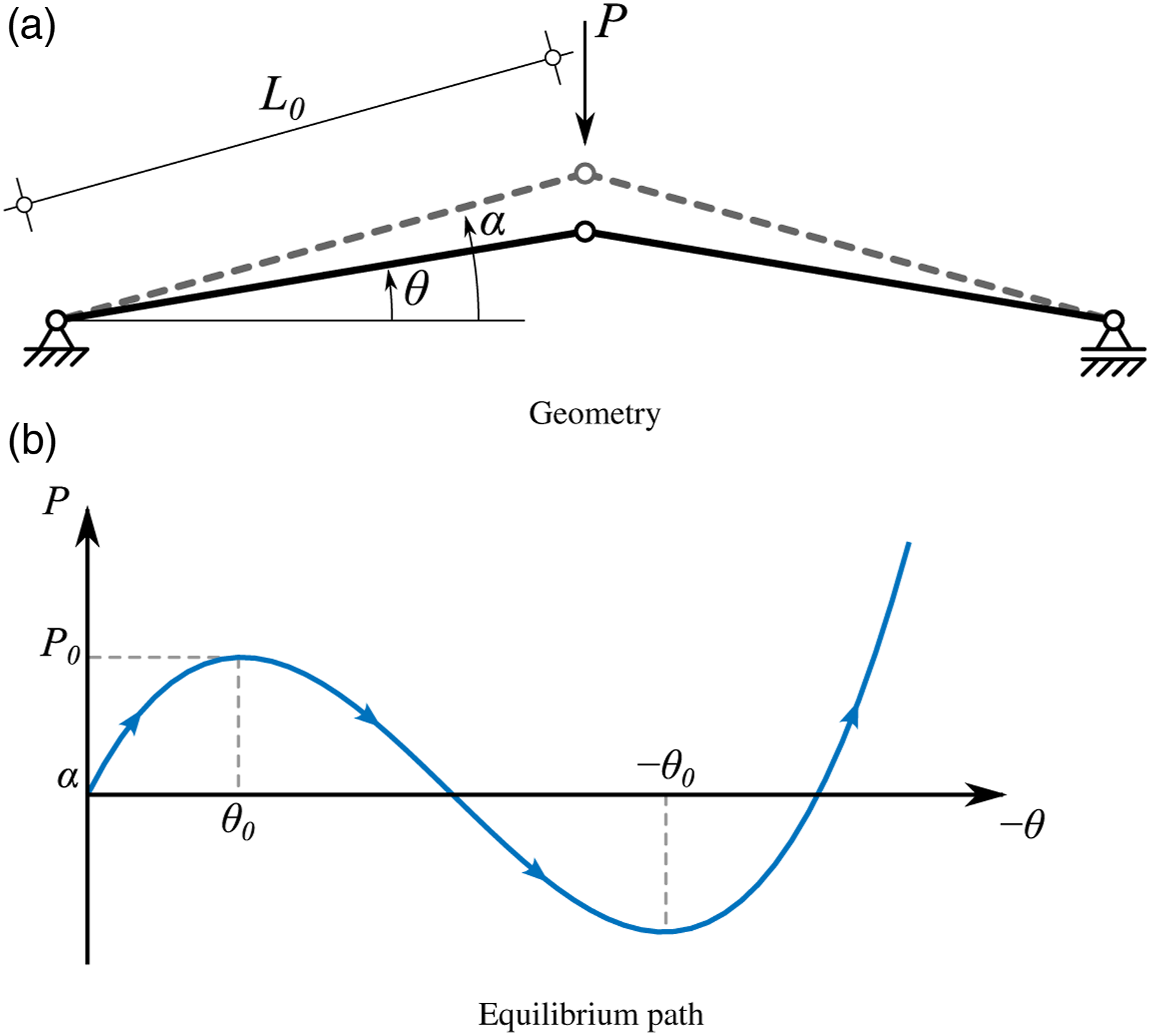

As referred, a third bar was added into the planar Von-Mises truss, resulting in a 3D bi-stable tripod, whose bars are placed 120º apart. Subsequently, the resulting equilibrium path is defined as

Analysing the evolution of the equilibrium path, illustrated in Figure 2b, one observes that almost no deformation occurs under constant force, which is not ideal for a protection solution that is intended to absorb energy. Therefore, in order to overcome this limitation, a spring was added at the centre of the bi-stable tripod, to increase the restitution force of the system during the snap-through phase. The resulting force is given by the following equation

Figure 3 illustrates the influence of the spring’s stiffness on the equilibrium path of the bi-stable tripod, considering the stiffness of the spring k
s
as a fraction of the tripod’s stiffness k
t
= EA/L0, specifically 1/100, 1/60 and 1/36. Observing the referred figure, it is possible to verify that the inclusion of the spring increases the required force to both initiate and carry out the snap-through phase which, ultimately, allows for a larger energy absorption since a constant compression force is required during the entire deformation. Effect of spring stiffness on the equilibrium path of the 3D Von-Mises truss.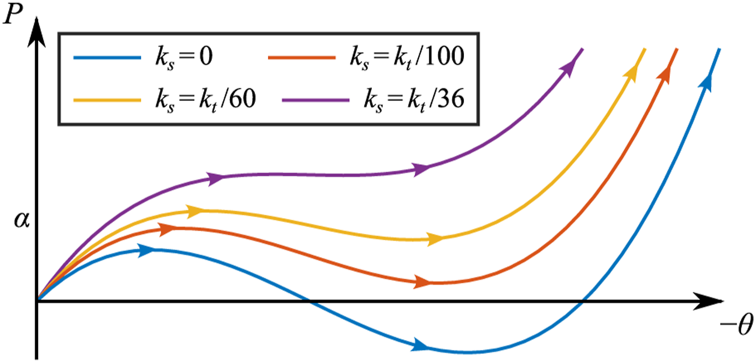
A preliminary parametric study allowed to establish that a force plateau around 300 N enables to maximise the internal energy of spring whilst minimising the internal energy of glass. Consequently, the bi-stable tripod was tuned to snap when a 300 N force is first reached.
A 3D printed bi-stable tripod tuned to snap when subjected to a 300 N force can be materialised, for instance, through the use of PLA thermoplastic (E = 2.75 GPa). Considering bars with an initial angle α = 8o, a length L0 = 0.045 m, a cross-section of 5×5 mm2 and a spring with a 47000 N/m stiffness, equation (3) yields a plateau of approximately 300 N.
Detailed numerical model of the bi-stable tripod A detailed numerical model was developed to verify if the explicit FE numerical code LS-DYNA Livermore Software Technology Corporation (2018) correctly simulates the non-linear behaviour of the bi-stable tripod. As depicted in Figure 4, beam elements (ELFORM 1) were used to model the bars of the tripod while a translational discrete element ensured the correct simulation of the spring. Similarly to what was performed in the other models, a NODAL_RIGID_BODY constrain was used to connect the tripod’s bars in terms of displacements, whilst allowing rotations. Therefore, the connection between the bars of the numerical model is similar to that of the Von-Mises truss, that is, a hinged connection. The displacements at the end of the bars and the spring were restrained in all directions. The centre node of the Von-Mises truss was subjected to a constant velocity (v = 0.005 m/s) by means of the BOUNDARY_PRESCRIBED_MOTION_NODE keyword, in order to attain the quasi-static behaviour of the protection solution. Numerical model of the bi-stable tripod with the additional spring.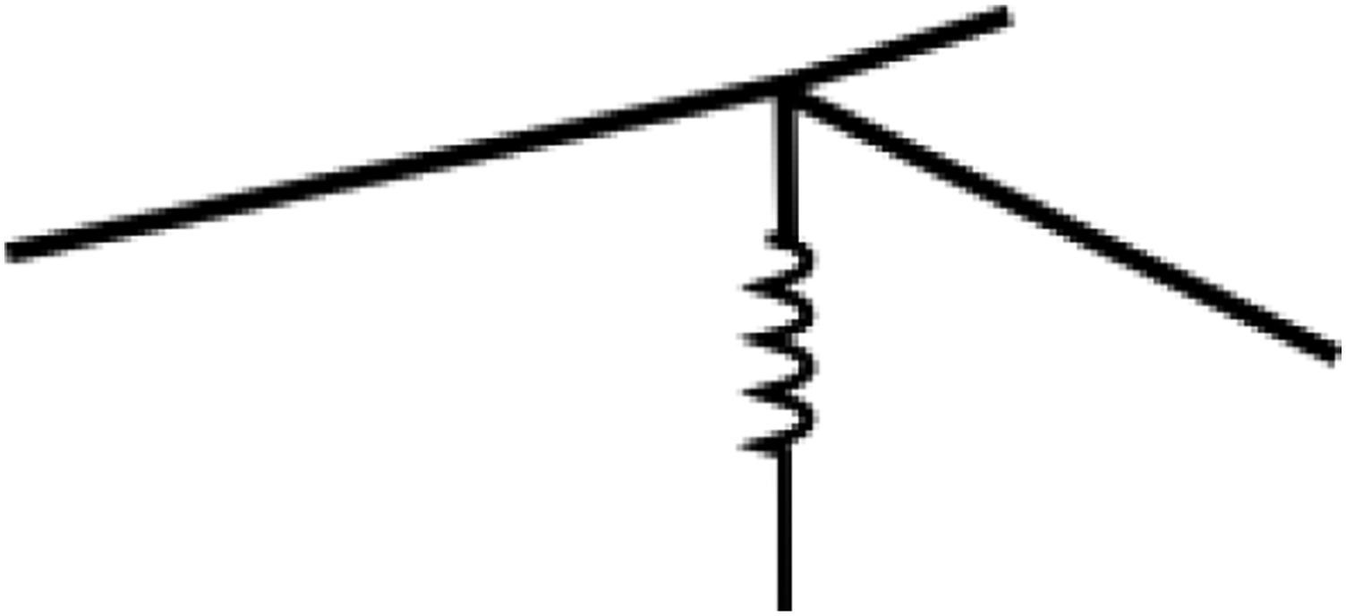
Material properties for FE numerical models.
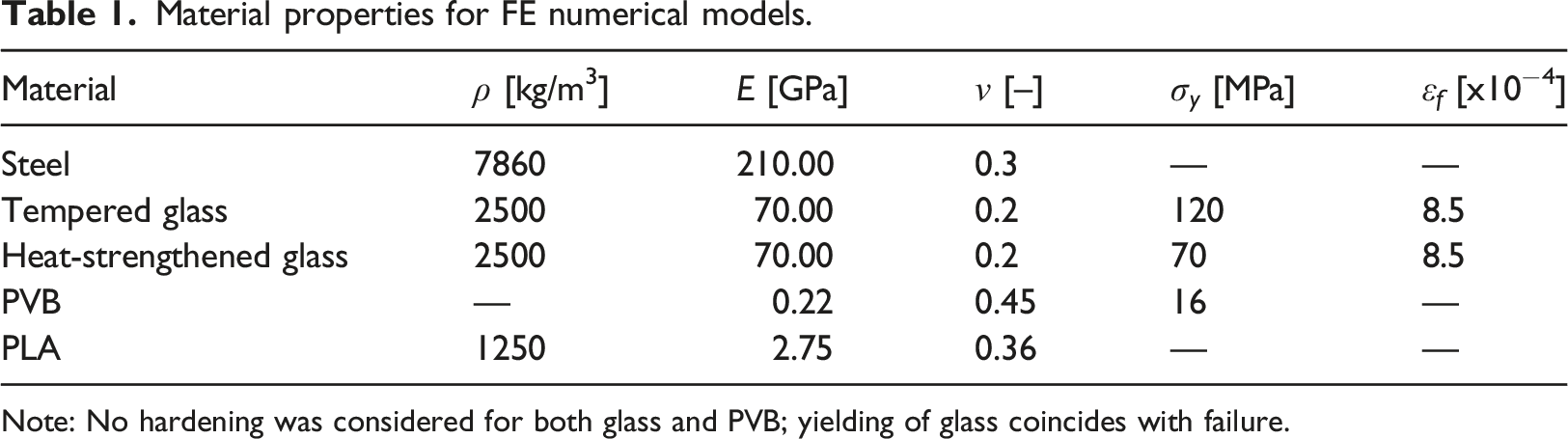
Note: No hardening was considered for both glass and PVB; yielding of glass coincides with failure.
Figure 5 illustrates the equilibrium path computed resorting to the numerical model, together with the one attained by means of analytical solution (equation (3)). Analysing the referred figure, one may observe that an excellent agreement between the numerical and analytical results was attained and, consequently, it is possible to conclude that the numerical model correctly simulates the non-linear behaviour of the bi-stable tripod. Equilibrium paths of the bi-stable tripod, based on analytical and numerical models.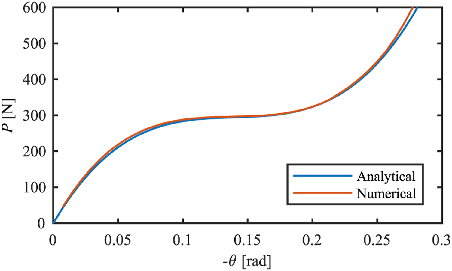
As previously referred, the detailed mechanical model of proposed protective solution will be implemented in both the window and facade numerical models, in order to address and quantify its effectiveness.
Materials For all the examined configurations, the spherical impactor was mechanically described using the RIGID material model, which considers the elastic properties of steel, illustrated in Table 1 for contact simulation. The non-linear behaviour of glass was simulated resorting to the Laminated Glass material model (MAT032). The referred material model considers that, in the case of double-layer glass panels bonded with a polymeric layer, the behaviour of shell elements is based on glass parameters until its failure strain is first reached. Subsequently, only the polymeric layer contributes to the residual stiffness of shell elements. One should note that the MAT032 material model assumes that no failure can occur in the polymeric layer Livermore Software Technology Corporation (2018). In order to fully characterise the glass panels, the user must specify the corresponding integration rule (INTEGRATION_ SHELL keyword). The location of integration points throughout the thickness of the glass and polymeric layer was computed according to the Gaussian quadrature points, using three thickness integration points in glass, while only two points were used in the bonding polymer. It is worth to note that, for all the simulations, the choice was based on tempered and heat-strengthened glass panes and Polyvinyl Butyral (PVB) as interposed bonding film. Table 1 presents the material properties for both glass and PVB bonding layers Ivanov (2006). Due to the low velocities associated with the loading scenarios used in this work, the strain-rate effects were not taken into consideration. This option is in-line with results previously published in Zhang and Hao (2016); Zhang et al. (2013). This way, it becomes possible to fully explore the development of a layered behaviour of the laminated glass, instead of a monolithic-like behaviour, which arises with the stiffening of the PVB interlayer subjected to very high strain-rates, which is a more conservative approach. Additional material properties are reported for steel (impactor), as well as for polylactide (PLA) thermoplastic, which can be used as a possible solution for materialisation of the dissipative system.
Numerical models of the glass panels
In order to study the performance of the proposed protective solution, two different numerical models were developed. The first model is a laminated glass panel representative of a conventional window solution, which was also used to conduct a mesh sensitivity study. The second model is a laminated glass panel representative of a facade element. The glass panels were geometrically described using a single layer of Belytschko–Tsay shell elements (ELFORM 2), while constant stress (ELFORM 1) solid elements were used to simulate the spherical impactor/steel ball. An AUTOMATIC_SURFACE_TO_SURFACE contact ensured the correct interaction between the glass panel and the spherical impactor, which was modelled with a given distance from the surface of glass and subjected to an imposed initial/impact velocity by means of the INITIAL_VELOCITY keyword. For the present study, several impact velocities were taken into account in the simulations. A selection of impact configurations is discussed in this paper and the target region was identified with the centre of the examined glass panels. The numerical models of the glass panels were analysed together with the numerical model of the proposed bi-stable tripod featuring an additional spring.
Window model The window model in Figure 6 was developed to evaluate the applicability of the proposed solution when used to increase the performance of conventional windows subjected to impact loads. The glass panel consisted of two 50 × 50 × 4 mm tempered glass layers with a 1.52 mm thick layer of PVB bonding film. For the purpose of the present study, the glass panel was considered to be clamped at four different points, along two opposing edges, and then subjected to the impact of a 514 g steel sphere, initially moving at impact speeds of 6.26 and 30 m/s, respectively. Axonometric view of window numerical model, with restraint detail.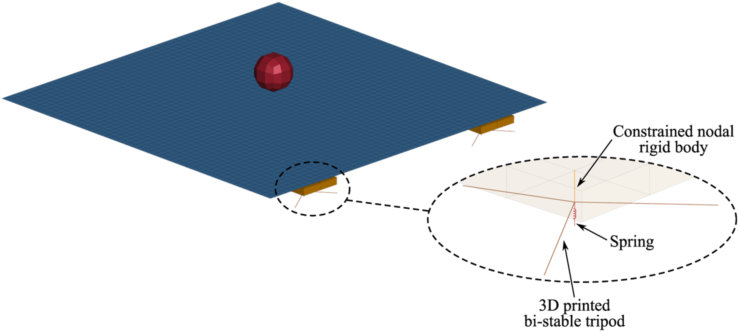
The clamped supports were simulated resorting to constant stress solid elements (ELFORM 1) and were fully restricted, for the FE model without the proposed protection solution. On the other hand, the out-of-plane displacements at glass restraints were released when the bi-stable tripod was included in simulations. To ensure the correct transmission of loads between the solid elements and the bi-stable tripod, a NODAL_RIGID_BODY constrain was defined for each support and tripod set, while a TIED_NODES_TO_SURFACE_OFFSET contact, with a soft constraint formulation, ensured the realistic simulation of contact between the glass panel and the supports. Lastly, one should note that, when simulating the contribution of protective solution, the base of the tripods was considered to be fully fixed.
Glass facade model Figure 7 depicts the glass facade model used in the present study to explore effectiveness of the proposed protection solution in the overall resistance of glass facades subjected to impact. A 2x1 m facade element consisting of a laminated glass panel with two 5 mm thick heat-strengthened glass sheets, and a 1.52 mm thick layer of PVB, was considered. Similarly to the window model, presented in Section 2.1.3, the glass facade was clamped at four different points along two opposing edges and subjected to the impact of a steel sphere (514 g) moving at an initial velocity of 30 m/s. Axonometric view of glass facade model (mesh hidden from view).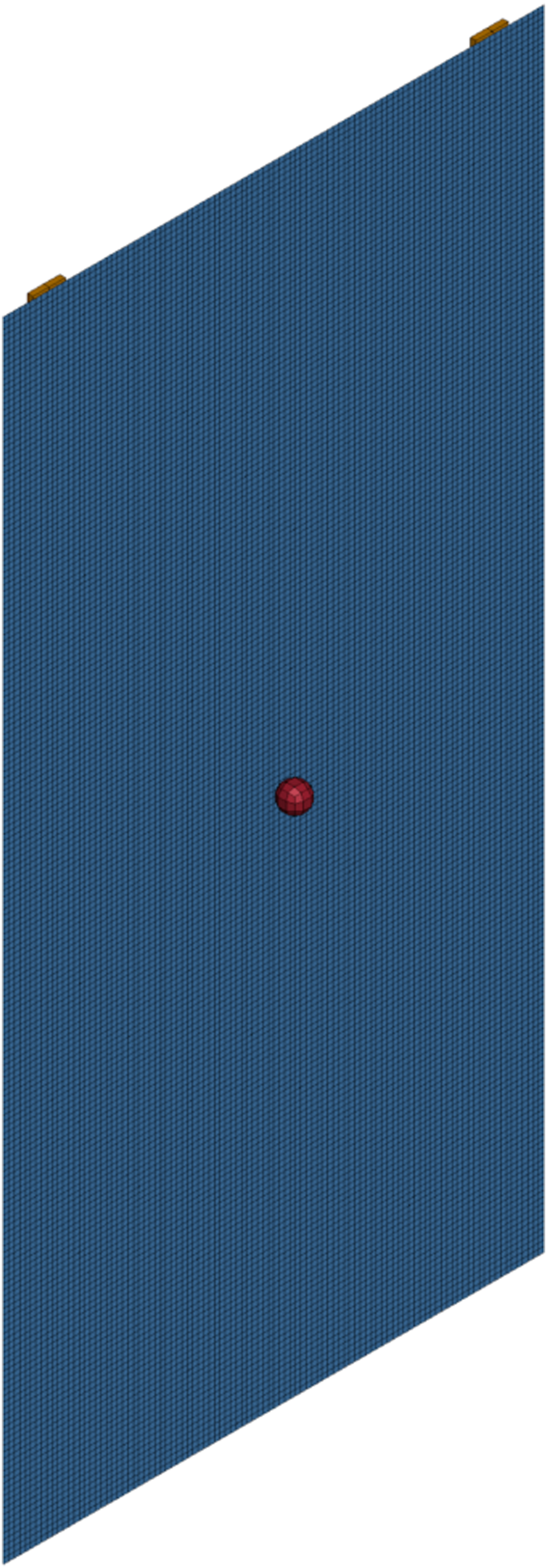
Mesh sensitivity analysis The mesh sensitivity of glass panels subjected to ball impact was analysed resorting to the window numerical model without the protective solution. The referred numerical model was subjected to the impact of a 514 g steel sphere, moving at an imposed impact velocities of 7.5 and 30 m/s. Mesh patterns with 25, 50, 100 and 200 elements along the borders, corresponding to 2, 1, 0.5 and 0.25 cm edge sizes, respectively, were considered for the present convergence study. The number of FE used to model the impactor was scaled accordingly, with 5, 8, 11 and 14 elements along the sphere’s radius for the FE models with 25, 50, 100 and 200 elements along the borders, respectively.
Figure 8 shows the collected parametric results in terms of mid-span displacement, when using the FE numerical model with 25, 50, 100 and 200 elements along the borders to simulate the glass panel subjected to a 7.5 and 30 m/s impacts. Analysing the displacement-time histories, one observes that, as expected, the mid-span displacement increases with mesh refinement. Nonetheless, it is possible to verify that the FE numerical model with 100 mesh elements at the border presents results very similar to those attained with 200 FE model, indicating that no significant differences were observed between the FE estimates obtained with the referred models. Mesh sensitivity analysis on the window numerical model’s displacement-time history.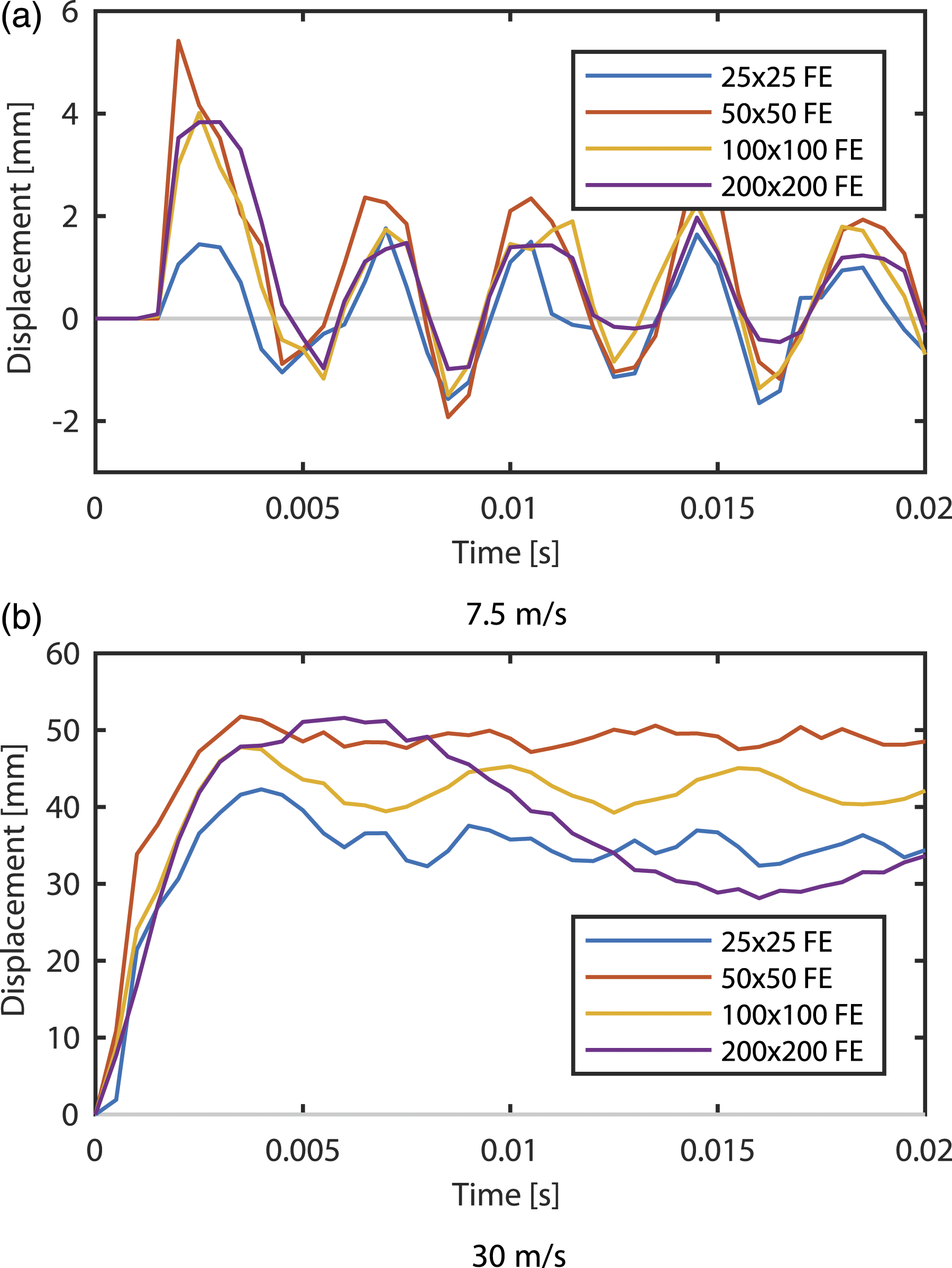
Moreover, in order to analyse the overall behaviour of the glass panel subjected to impact, Figure 9 illustrates the energy-time history of the developed numerical models, namely, the internal energy of the glass. Similarly to that observed for the displacement-time history, the numerical model with 100 mesh elements at the border presents results very similar to those attained with the 200 FE model. This shows that the overall behaviour of the glass panel subjected to impact is adequately computed with 100x100 FE mesh. Consequently, all subsequent numerical models and simulations were developed resorting to a FE mesh pattern with 5 mm long edges. Mesh sensitivity analysis on the window glass’s internal energy-time history.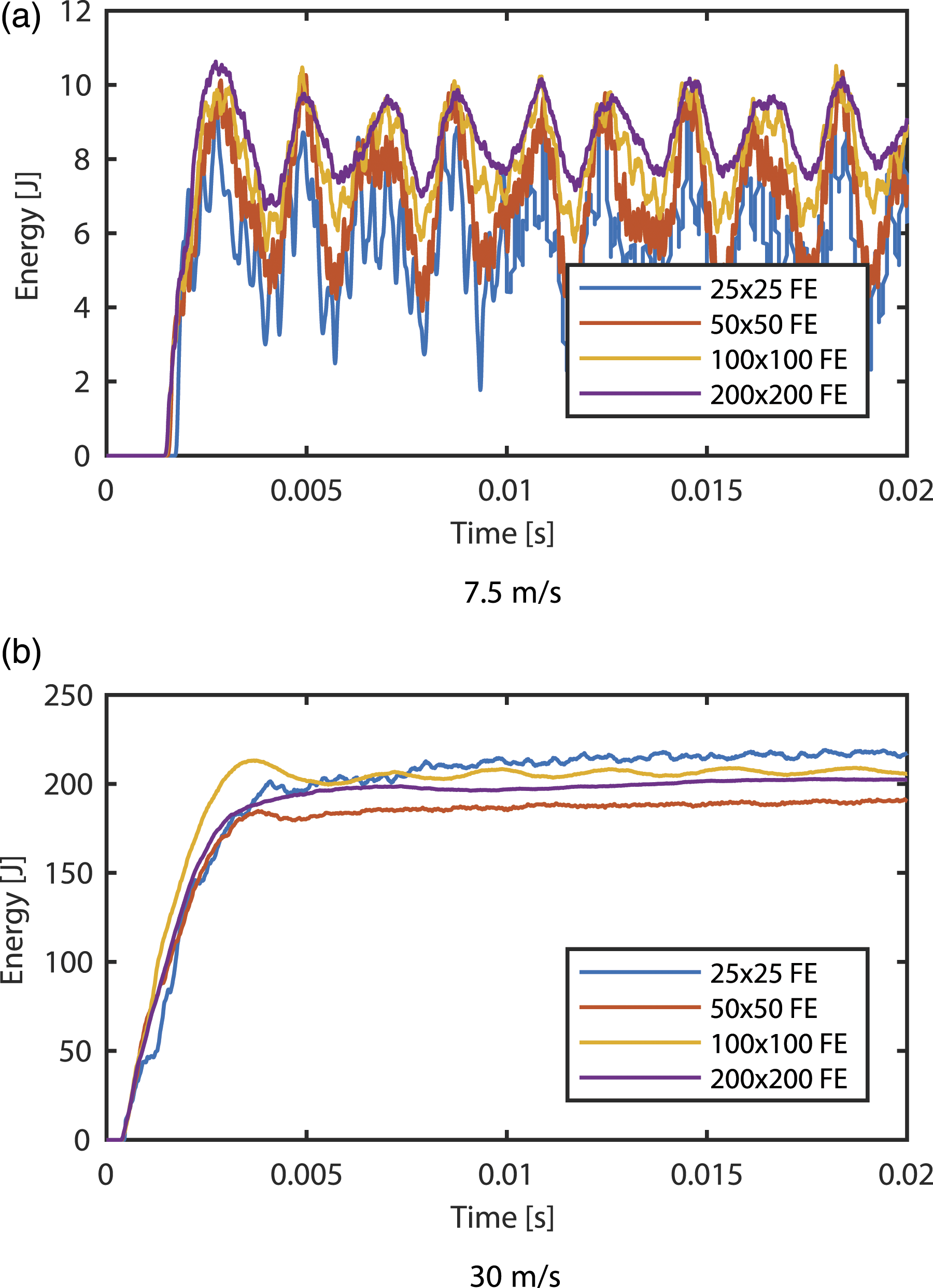
Numerical results
The analysis of the results was primarily focused on the assessment of the kinetic and internal energy contributions of the projectile and tested glass panels, respectively, so as to analyse the effectiveness of the proposed supports in terms of absorbed energy under impact. Additionally, the transmitted force at the base of the supports (which allows to verify if a reasonable force reduction is attained), and the effective plastic strain of both glass layers and PVB film (to visualise possible damage extent) were also taken into account.
Window model
Impact response under 7.5 m/s initial velocity Figure 10 depicts the kinetic and internal energy-time histories of the projectile and glass panel, respectively, when the latter is subjected to a 7.5 m/s impact. One may observe that the use of the proposed bi-stable tripods greatly reduces the kinetic energy of the impactor. However, no significant change to the behaviour of glass is observed in terms of internal energy. Energy-time histories of window model under 7.5 m/s impact.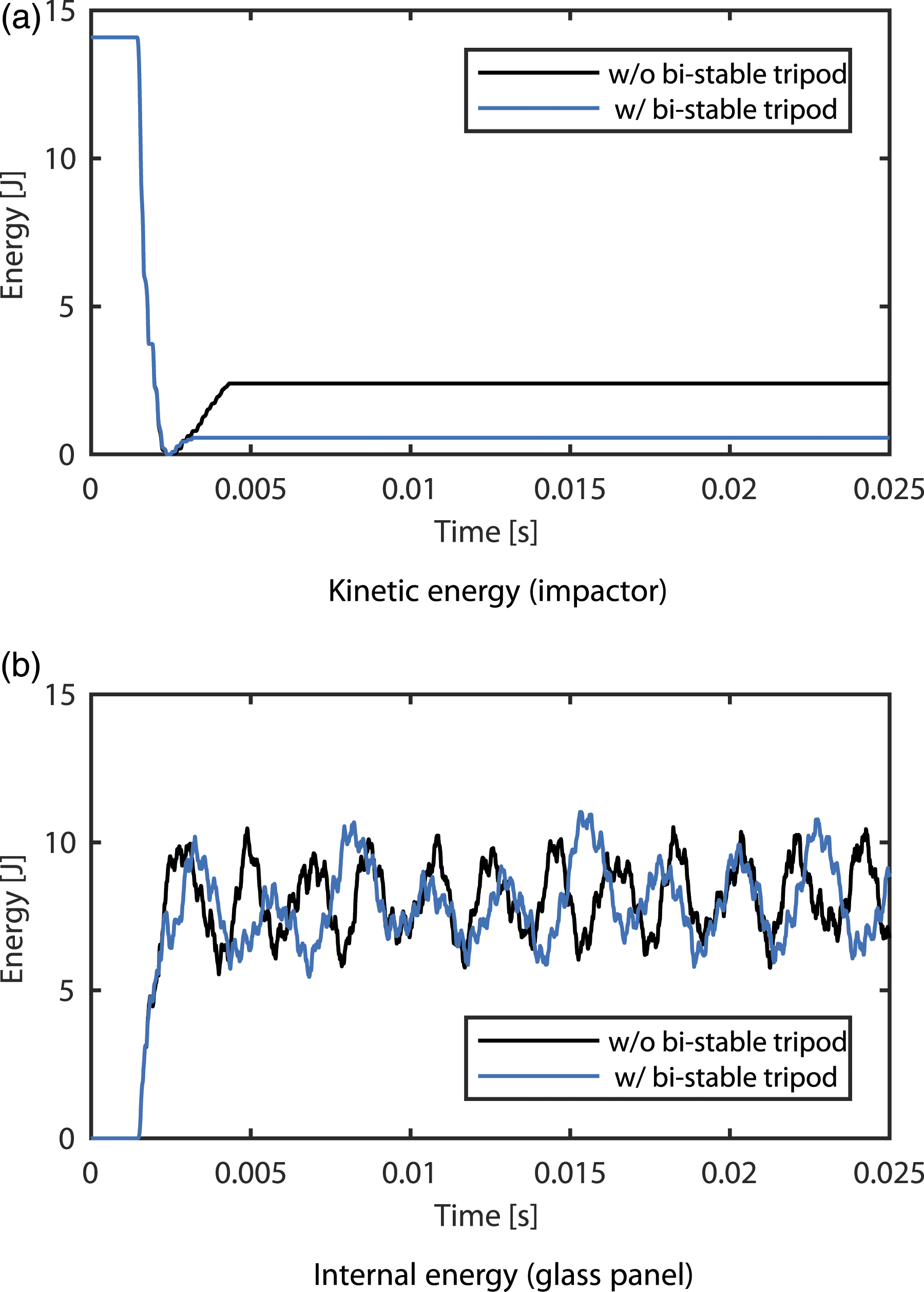
To further evaluate the performance of the protective solution, Figure 11a presents the transmitted force-time history obtained resorting to the developed numerical models for the unprotected and protected glass panels, respectively. A marked drop reduction in transmitted force can be observed when the bi-stable tripod is used, clearly revealing a limitation of the force which is transmitted to the main building structure. Nonetheless, through the analysis of the equilibrium path in Figure 11b, one may verify that the plateau was not reached under compression. Force-time history and resulting equilibrium path of window model under 7.5 m/s impact.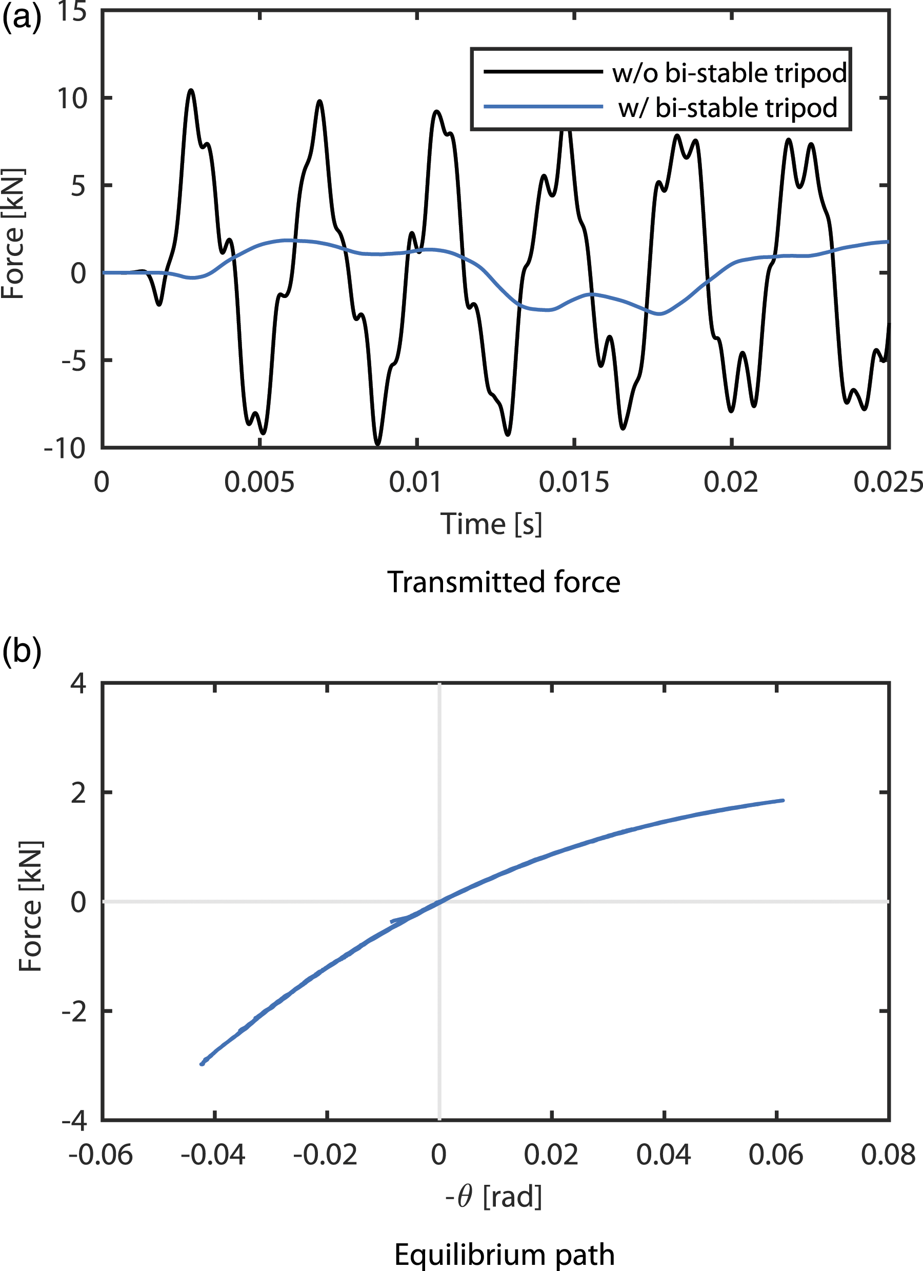
Figure 12 shows the effective plastic strain observed at the end of numerical simulations in the glass (top and bottom layers) and PVB integration points. Note that the top numerical integration point in glass corresponds to the outer integration point on the projectile’s side, whilst the bottom integration point is on the opposite face. Effective plastic strain of window model under 7.5 m/s impact.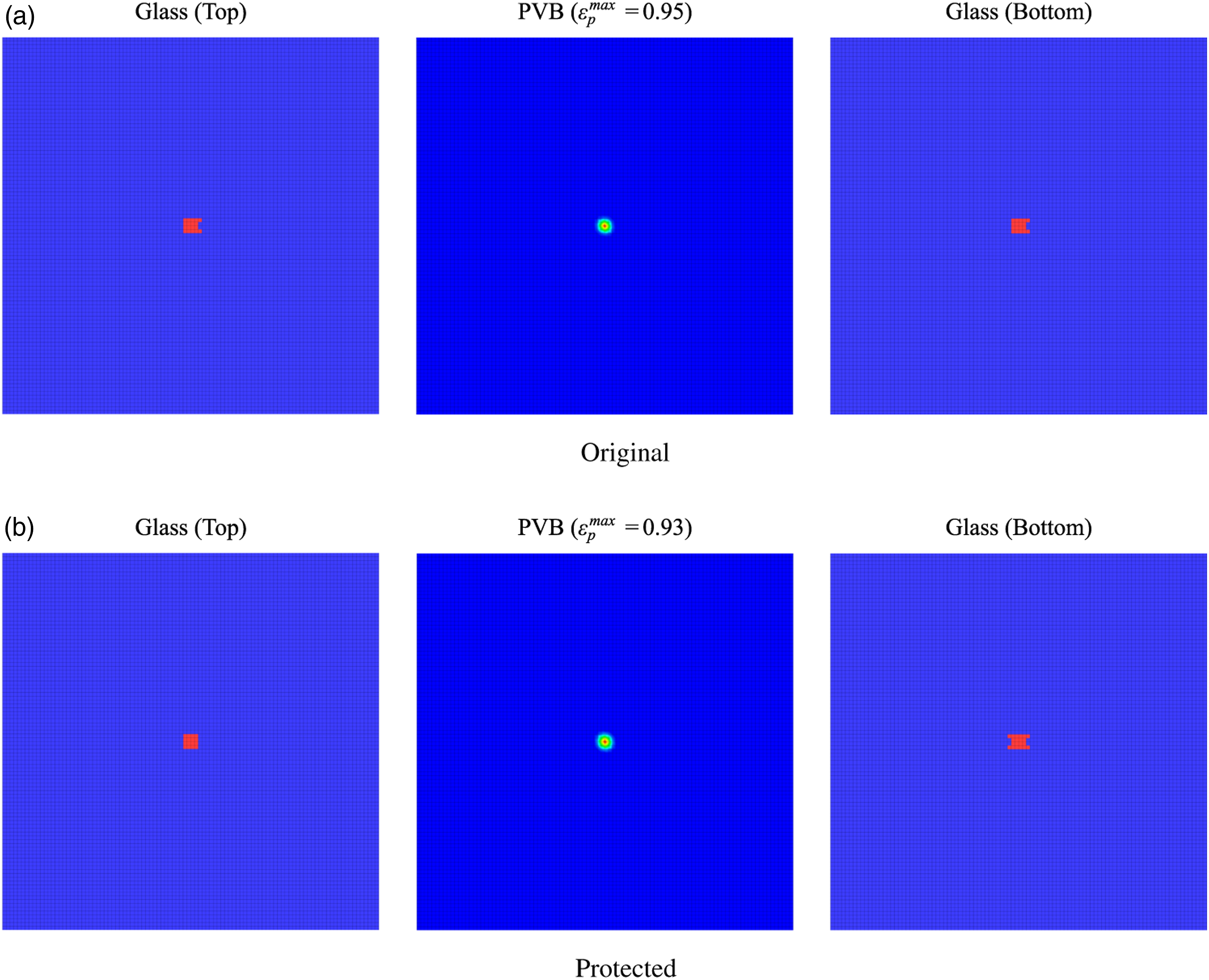
Observing the referred figure, it is possible to note that the attained damage is mostly concentrated around the impact region and that, as expected due to the similar internal energy depicted in Figure 10b, both damaged areas are very similar, indicating that the proposed protective solution did not improved the glass panel’s performance to impacts.
Additionally, the stress difference attained due to the use of the proposed 3D printed bi-stable tripod was studied. Figure 13 illustrates the maximum principal stress determined resorting to the unprotected and protected glass panel’s numerical models. Note that the presented stress corresponds to the maximum observed throughout the entirety of the analysed time. Observing the referred figure, one may verify a substantial stress reduction (50%) due to the use of the proposed protective solution, clearly showing an improvement in performance. Maximum principal stress of window model under 7.5 m/s impact around the supports.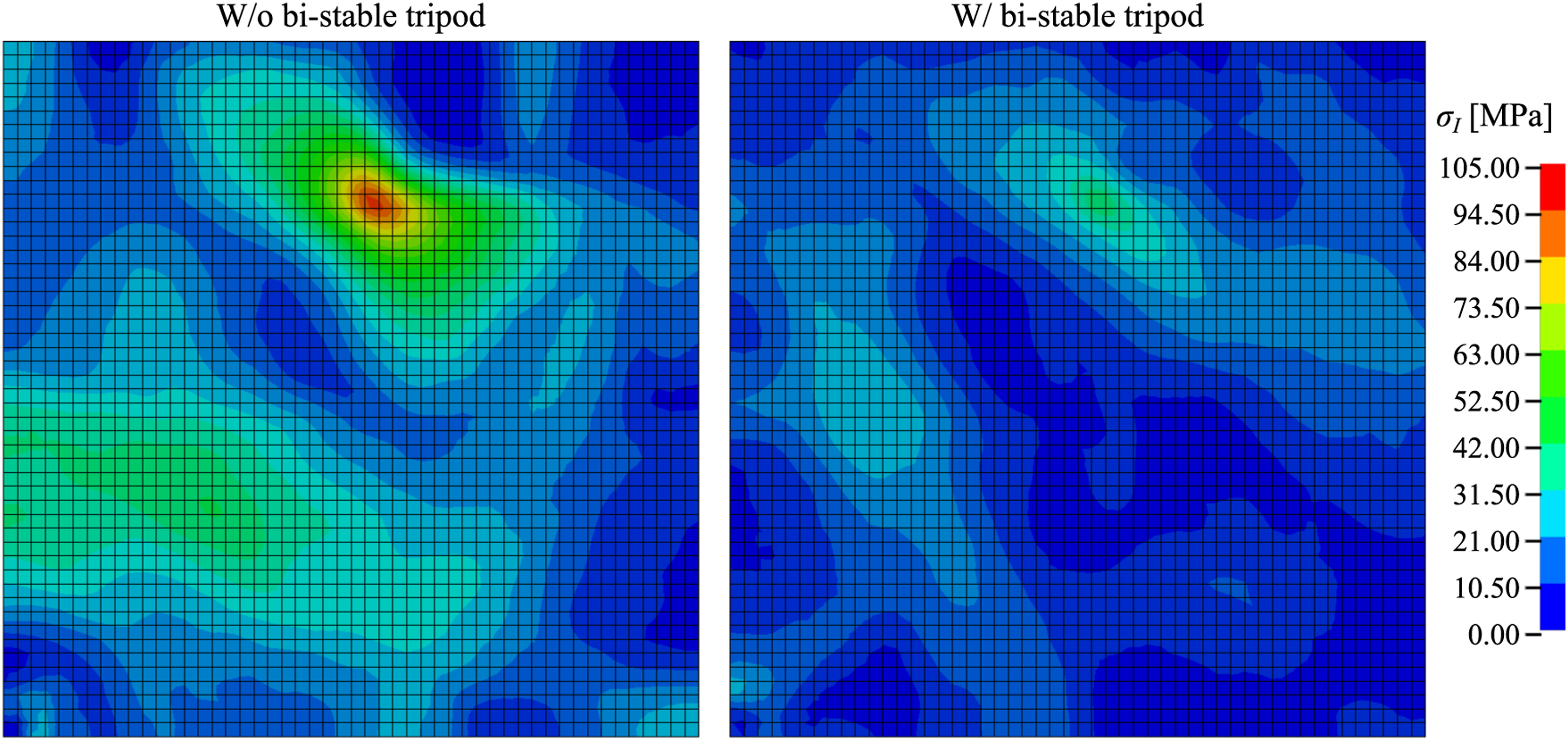
Impact response under 30 m/s initial velocity Figure 14 illustrates the recorded energy-time histories when the glass panel is subjected to a 30 m/s impact. Similarly to that observed for the 7.5 m/s impact, the protected glass panel exhibits an improved performance in terms of energy, since a reduction in both energies can be verified immediately after the impact. One should note that the increase on the glass panel’s internal energy arises from its free vibration after the impact took place since no damping was used in the FE model. Energy-time histories of window model under 30 m/s impact.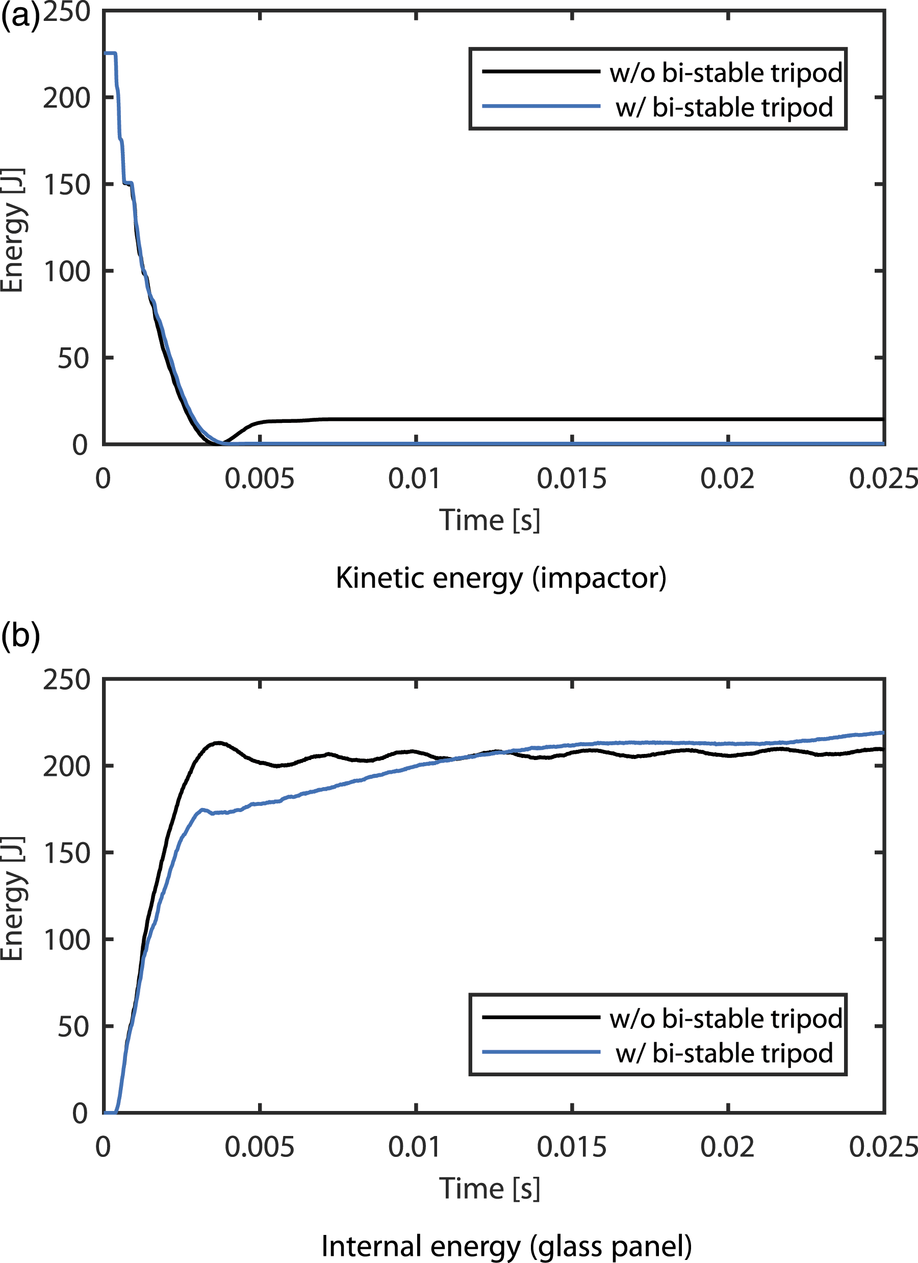
The corresponding transmitted force-time histories for the unprotected and protected glass panels are depicted in Figure 15a, and show a clear reduction in force during the initial compression phase (with bi-stable tripod). Analysing the bi-stable tripod’s equilibrium path, one may verify that the plateau stage was reached during the initial compression phase, since the nearly reached a null value at an angle of approximately 1.7 rad, whilst no plateau stage is present throughout the tensile path. Force-time history and resulting equilibrium path of window model under 30 m/s impact.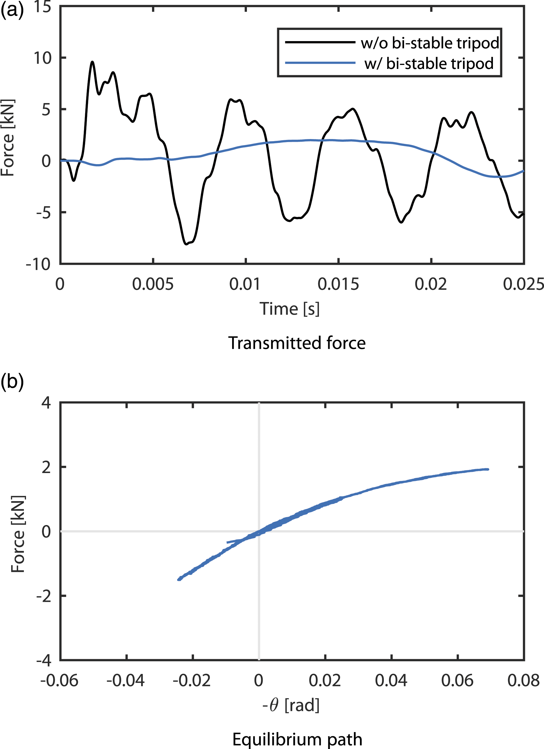
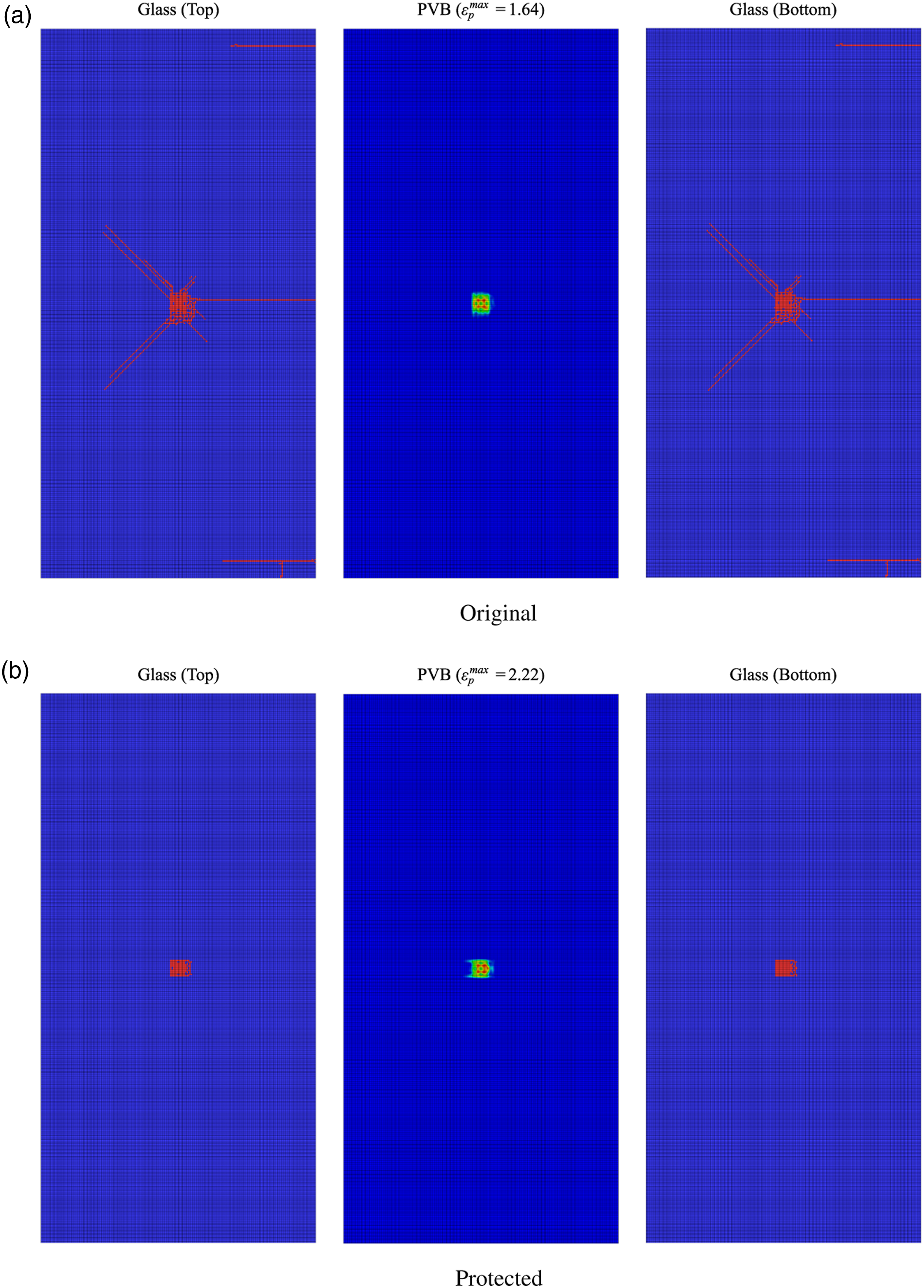
The effective plastic strains illustrated in Figure 16 clearly yield a damage reduction when the protective solution is applied to the glass panel. Specifically, no damage occurs around the supports, which indicates a significant improvement in performance, given that fracture around the supports may ultimately lead to the detachment of the glass panel from restraints and its subsequent fall-out/collapse. Effective plastic strain of window model under 30 m/s impact.
Further analysis of the presence of damage around the supports was carried out resorting to the maximum principal stress distribution depicted in Figure 17. Analysing the referred figure, it possible to conclude that, as expected due to absence of damage around the supports, a lower maximum principal stress is attained when the 3D printed bi-stable support is used to improve the performance of the glass panel. This reduction is particularly significant since the maximum principal stress obtained when no dissipative solution is used reaches the tempered glass’ yield stress. Maximum principal stress of window model under 30 m/s impact around the supports.
Glass facade model
The glass facade numerical model was successively investigated, to verify the applicability of the developed protective solution when used to increase the performance of glass facades. Similar to the window model, the kinetic and internal energy of the projectile and glass, respectively, are shown in Figure 18. No significant difference can be observed in terms of energy. Energy-time histories of glass facade model under 30 m/s impact.
Nonetheless, through the analysis of Figure 19a, one may verify that a significant force reduction under compression was observed when the protective solution was applied to the glass facade. Moreover, the effective plastic strains, depicted in Figure 20, clearly indicate that the proposed bi-stable tripods are able to reduce the force transmitted at the supports, but also to significantly reduce the damaged area in glass. Finally, Figure 19b depicts the resulting equilibrium path of the developed supports when the glass facade is subjected to 30 m/s impact. Force-time history and resulting equilibrium path of glass facade model under 30 m/s impact. Effective plastic strain of glass facade model under 30 m/s impact.
Similar to that previously conducted, the attained maximum principal stress near the supports was analysed in order to verify if the proposed protective solution increases the performance of the glass facade. Figure 21 clearly depict a stress reduction, from a stress concentration near the support’s corner whose value reaches the heat-strengthened glass’ yield stress (70 MPa) to a more even stress distribution that does not surpass approximately 30 MPa. Therefore, as previously evidenced by the observed damage reduction around the supports, the use of the 3D printed bi-stable tripods improves the performance of the glass facade when subjected to a 30 m/s impact. Maximum principal stress of glass facade model under 30 m/s impact around the supports.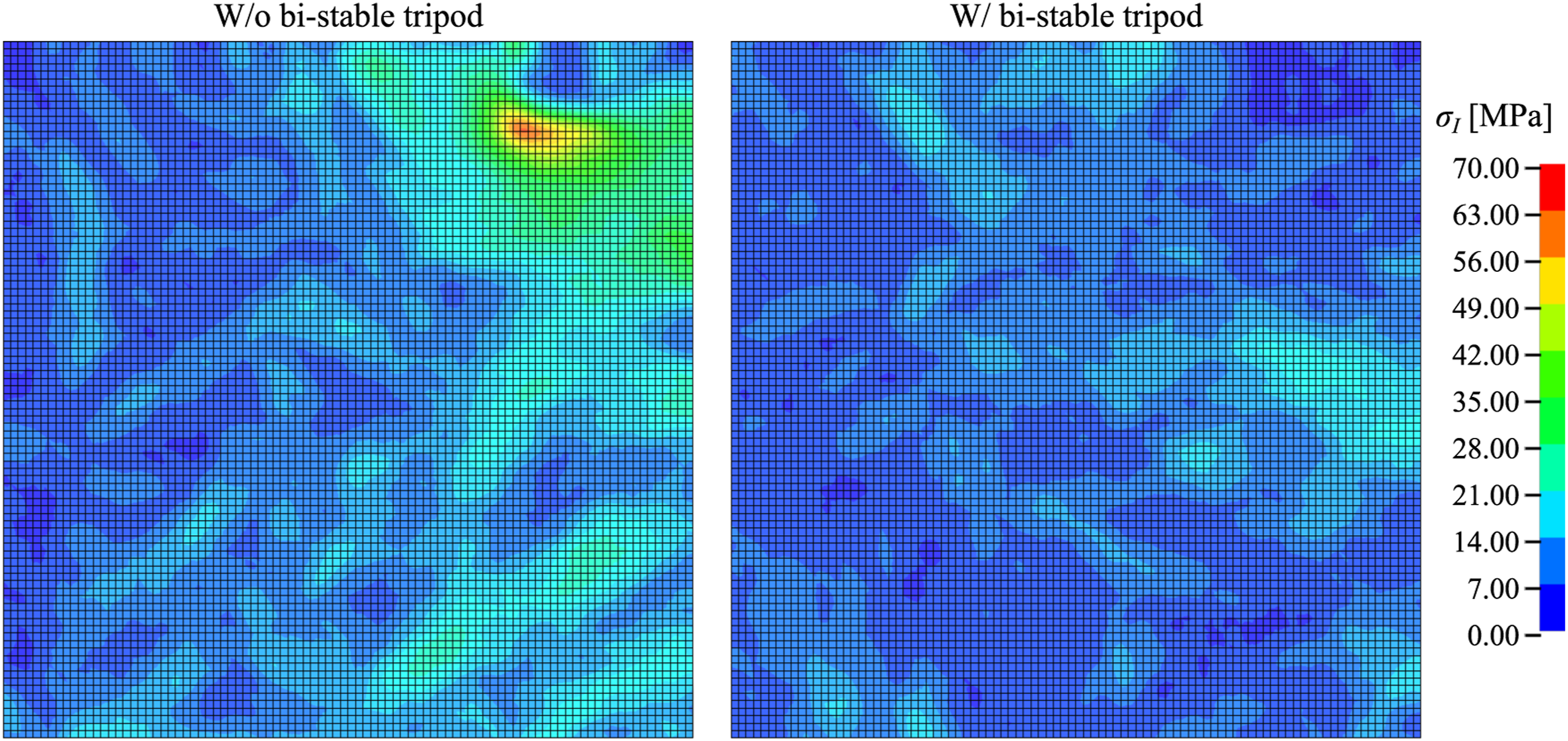
Discussion of results
The goal of the present study is to evaluate the applicability of the proposed protection solution, specifically the bi-stable tripod, when used to increase the performance of glass panels subjected to impact loads.
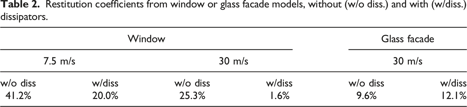
The results presented in the previous section demonstrate that the proposed protective solution is able to improve the performance of selected glass panels under impact, mostly by limiting the force which is transmitted to the main structure through the tripods, and, hence, controlling the damage in the panels around the support points. This is particularly important since it prevents the glass panels from detaching and falling upon impact loading scenarios, such as the ones considered in the present study. An additional analysis in terms of the restitution coefficient, energy and strain-rate effects was carried out and herein presented, to further support the understanding of the developed protective solution’s influence on the glass panel’s performance.
Restitution coefficient
Restitution coefficients from window or glass facade models, without (w/o diss.) and with (w/diss.) dissipators.
Energy analysis
Figure 22 depicts the internal energy of the support, showing the difference of models with and without the Von-Mises bi-stable tripod (w/o support. − w/support), as well as the total energy of glass panel (i.e., the sum of internal and kinetic energies), and impactor’s kinetic energy. Note that, if a positive energy value is obtained for a given time instant, the numerical model without support yields a larger energy at that instant. Similarly to previously reported results, and specifically analysing the energy variations, it possible to verify that the presence of protective solution reduces the kinetic energy of the impactor (after contact) for all the considered FE models except the facade panel, since a positive energy difference is attained. Time histories of dissipator’s internal energy, glass panel’s total energy, and impactor’s kinetic energy.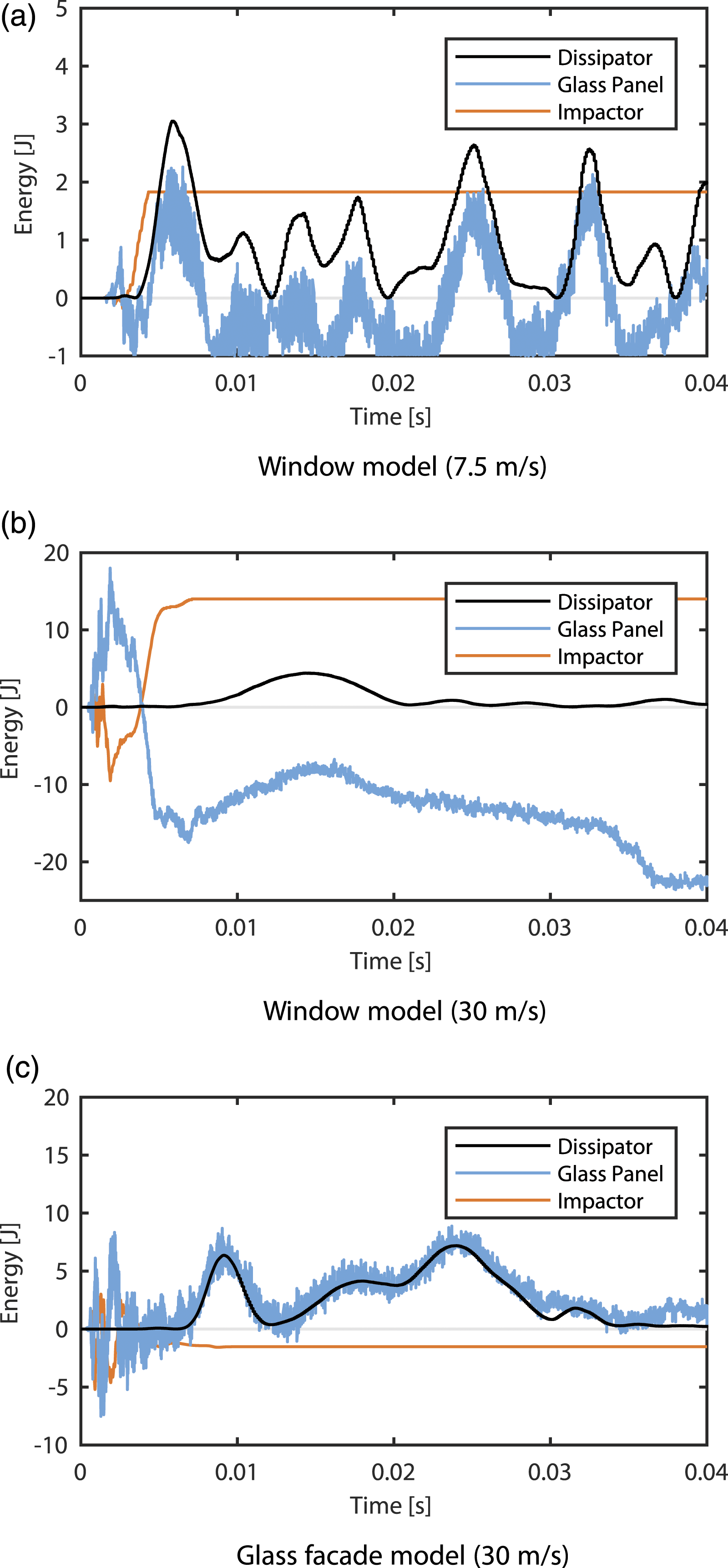
On the other hand, through the observation of the glass panel’s total energy, in combination with the internal energy of the support, one may conclude that for the glass facade numerical models, the energy in the support corresponds, in almost its total amount, to the difference between the total energy of glass panel. However, that may not be observed for the window system (7.5 m/s), since a large portion of energy difference arises from the kinetic energy of impactor. Moreover, similarly to that previously observed, Figure 22b indicates that the presence of the protective solution increases the total energy of the window glass panel under a 30 m/s impact.
Influence of impact velocity
Lastly, the influence of the impact velocity on the behaviour of the bi-stable tripod was analysed resorting to the previously reported equilibrium paths. Figure 23 illustrates these equilibrium paths, where it can be noted that differences are negligible. Therefore, it is possible to conclude that the impact velocity does not influence the non-linear behaviour of the developed protective solution, and this is considered an advantage in developing an efficient energy absorbing solution whose deformation might be considered as stable and repeatable Lu and Yu (2003). Equilibrium path of glass window and facade models under various impact configurations.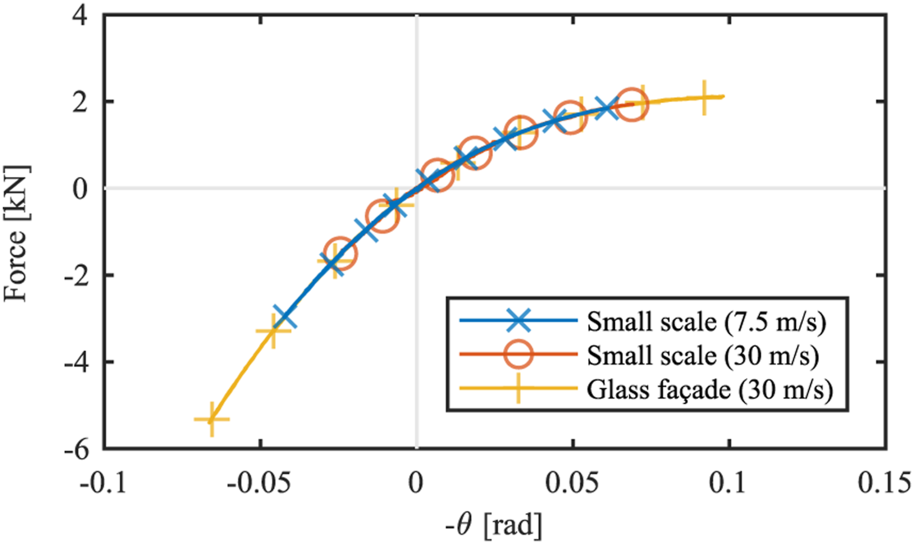
Conclusions
The present paper addressed the impact response of point-fixed glazing systems when equipped with newly designed, bi-stable supports. Based on parametric Finite-Element (FE) numerical simulations carried out on two different glass systems, under various impact conditions (namely, a conventional window model and a glass facade model), the proposed study showed that the developed tripod absorbers can greatly enhance the robustness of point-fixed glass panels of typical use. Major advantage is derived by limitation of the force which is transmitted to the main building structure when the facade us subjected to impact events. As discussed from the parametric investigation, such a feature has a key role in glass damage mitigation, especially in the vicinity of supports, thus preventing failure for the overall glazing system and subsequent fall-out of glass panels, with potential risk for people. Nonetheless, further analysis is required to fully understand the use and adequately design of bi-stable supports as a protective solution.
Footnotes
Declaration of conflicting interests
The author(s) declared no potential conflicts of interest with respect to the research, authorship, and/or publication of this article.
Funding
The author(s) disclosed receipt of the following financial support for the research, authorship, and/or publication of this article: This work is part of the research activity carried out at Civil Engineering Research and Innovation for Sustainability (CERIS) and has been funded by Fundação para a Ciência e a Tecnologia in the framework of project UIDB/04625/2020.