
Abstract
Modern railroad infrastructure is subject to blast vibrations. The dynamic safety of an operating railroad under the influence of tunnel blasting is a primary problem for metro development in urban areas. In this paper, the blasting excavation of Wuhan Metro Line 5 was selected as a case. The ballast rail- sleeper- ballast bed composite structure numerical model was developed and validated in order to evaluate the ballast railway’s safety. The smoothed particle hydrodynamics element was chosen to replicate the ballast bed due to the instability and unpredictability of the ballast bed constructed from crushed stone. Further analysis was conducted on the dynamic response characteristics of the ballast rail-sleeper-ballast bed composite structure. On the basis of the parameter calculation and analysis, a prediction model of the blast vibration velocity of the ballast rail under blasting conditions was developed. Next, the rail was simulated as a semi-infinite Euler beam and placed on the Kelvin foundation to calculate the rail displacement at the train’s limited operation speed. By substituting the maximum rail displacement when the train is running at maximum speed into the rail velocity prediction model, it is possible to determine the maximum blast velocity that the rail can withstand in this instance. In this case, the ballast bed, sleeper, and ballast rail were also deemed safe.
Introduction
Due to the global pandemic of Covid-19, several countries’ economies have been severely impacted. Infrastructure construction is once again a viable option for stimulating the economy. With the implementation of China’s trillion-dollar infrastructure plan, urban subways have garnered considerable interest. Inevitably, important structures will be crossed during the construction of the urban subway (Jiang et al., 2022b, 2023). Although, the shield machine has been widely adopted in the urban subway tunnel excavation, the drilling and blasting method also play a key role in the excavation of hard rock tunnel (Wu et al., 2022a). In the meantime, the blasting vibration caused by this method would induce the failure of the adjacent structures (Anas and Alam, 2022a; Wu et al., 2022b; Zhao et al., 2022; Zhu et al., 2022).
As a vital component of the nation’s infrastructure, the railroad is the backbone of the entire national transportation system. Due to the enormous number of passengers and fast speed, train accidents will result in a large number of fatalities. From the 1980s until the 2020s, derailment was the leading cause of railroad accidents. For example, In the Hatfield rail crash in England in 2000, which killed four people, rolling contact fatigue had resulted in multiple gauge corner cracking in the surface; 300 such cracks were subsequently found at the site. The rail cracked under a high-speed passenger train, which derailed (Walker, 2002). The Polmont rail accident in the UK in 1984 caused 13 persons died in the derailment (Her Majesty’s Stationery Office, 1984). The Poorva Express derailed in the outskirt of Kanpur Central near Rooma in India in 2019, which injured 15 persons (India Today, 2019). Therefore, it is necessary to assess the safety of operating railway above the tunnel which excavated by the drilling and blasting method.
In the area of blasting research, experimental and numerical simulations are the main research methods (Anas et al., 2021a). Due to the danger of explosions and the constraints of various factors, it is not realistic to fully recreate the blasting scene, so in the area of blasting, experiments are mostly conducted on building components. Many scholars have carried out a lot research on the dynamic response and damage of building components (Anas et al., 2020; Anas and Alam, 2022b). Lu et al. designed a unique experimental program to simulate the ground shock response on scaled reinforced concrete frame models with an electromagnetic shaker, to obtain the relationship between allowable PPV and input frequency (Lu et al., 2002). Wu et al. discussed the effects of different media on the stress wave propagation which based on that the attenuation relations of the peak particle acceleration (PPA), peak particle velocity (PPV) and especially the principal frequency (PF) of the stress wave on the soil surface, inside the soil mass and on the rock–soil surface is derived (Wu et al., 2003).
Due to their excellent operability and the advancements in computer science, numerical simulation methods are also frequently employed in the field of blast vibration research. Lu and Wang adopted a coupled numerical approach with combined Lagrangian and Eulerian methods to allow for the incorporation of the essential processes, namely the explosion, shock wave propagation, shock wave-structure interaction and structural response, in the same model. (Lu and Wang, 2006). Wu et al. performs the dynamic response analyses of structures resting on a layer of a sand base subjected to blast induced ground excitations in commercial software Autodyn3D (Wu et al., 2004). Wu et al. performs a 3-dimensional dynamic response and damage analysis of masonry and masonry infilled RC frame structures to blast induced ground excitations (Wu et al., 2005). Anas et al. conducted a numerical simulation investigation through FEM-based dynamic computer code, ABAQUS/Explicit, to study the location of impactor of the maximum damage caused by drop weight impacting on the RC slab, and the results showed that the most critical location of the impact is the eccentric one with the eccentricity of 1/6th of the span from the slab centroid along the mid-span (Anas et al., 2022a). Anas et al. built a 3D-FE model of the clay brick masonry wall braced with two transverse walls one at each end to study the performance of the C-FRP wrapping and steel angle-strip system for strengthening the wall (Anas et al., 2022c). Jiang et al. studied the dynamic response of the pipeline induced by blasting vibration and the possible damage characteristics of the pipeline (Jiang et al., 2022b). He et al. monitored the buildings above the subway tunnel blasting and used the Hilbert-Huang transform (HHT) model to extract and analyze the time-frequency characteristic parameters of the blasting dynamic response signal. By using intrinsic mode function (IMF) component frequency and instantaneous energy to replace the main frequency and total input energy of blasting, the time-frequency instantaneous energy characteristics of buildings under blasting seismic load are analyzed, and the concept of effective vibration duration is proposed (He et al., 2022).
Seismic waves are similar to vibration waves generated by blasting, so the effects of seismic waves on railroad systems can be analogized to blasting waves. Jiang et al. pointed out that the safe running speed limits of the high-speed train increased to 250 km/h and 100 km/h under frequent and design earthquakes, respectively (Jiang et al., 2022a). Lai et al. based on the model provided by Berkeley, the rail unevenness corresponding to the lateral residual deformations in the HSR track-bridge system has been evaluated. The superposition of the mapped rail deformations accords with the residual rail deformations obtained from the FE results. The framework developed in this study provides an effective methodology to evaluate the contributions of lateral residual deformations of different components to the lateral rail unevenness on the HSR track-bridge system after seismic shaking (Lai and Jiang, 2022). Yarahuaman et al. a rail embankment specimen was constructed and tested under an actual earthquake motion. The applied motion induced a maximum horizontal rail acceleration of 1.38 g but only a small residual cross-level variation of only 0.66 mm was measured (Yarahuaman and McCartney, 2022). In the meantime, some scholars had introduced rail displacement as the index of railway damage. Hu et al. established a train-track-bridge system (TTBS) model and introduced the lateral irregularities of the lateral displacement amplitude of the rail and proposed lateral displacement as an index to measure the damage of the truck structure (Hu et al., 2022). Ma and Choi evaluated for the maximum standard deviations of bridge accelerations, train accelerations, the wheel-rail contact force, and the offload factor. The results show that these influences significantly affect the stochastic dynamic responses of the train-track-bridge system (Ma and Choi, 2022).
Allowable safety standard of blasting vibration.
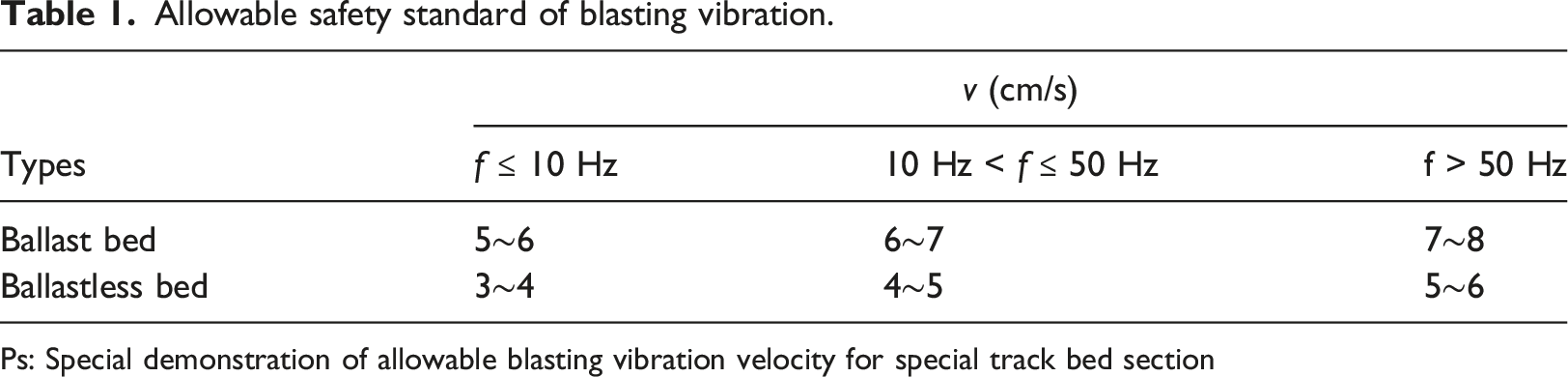
Ps: Special demonstration of allowable blasting vibration velocity for special track bed section
However, there are few studies on the dynamic response characteristics of underground blasting vibration to rail and railroad bed. At the same time, the existing research is mostly concentrated on ballastless track, and the research on ballast track is very few. Broken stone is used as a damping part in ballast track with great damping performance, but it is greatly affected by displacement and dynamic stress (Liu et al., 2018). Therefore, it is necessary to study the dynamic response characteristics of the upper rail and ballast bed under the blasting vibration of the tunnel.
This research focuses on how the blasting load of a subway tunnel affects the ballast rail and ballast bed. The vibration of the railway embankment is monitored during tunnel blasting based on the tunnel blasting project for the Peng Si segment of Wuhan Metro Line 5. Using the finite element analysis software LS-DYNA, a three-dimensional numerical model of practical engineering is built. Field monitoring is used to confirm the validity of the numerical simulation model. On the basis of the validated numerical simulation model, the dynamic response characteristics of the railway structures that cannot be monitored on-site under the influence of blasting dynamic load are analyzed, and the operational safety of ballast rail and ballast bed is evaluated based on existing research, applicable national standards, and norms. The importance of the research findings in assuring the safety of railway structures and train operations is substantial.
Background and field experiment analysis
Background of underpass blasting engineering
Blasting Project is located on Wuhan Metro Line 5 between Pengliuyang Station and Simenkou Station. There is a double-track tunnel between Pengliuyang Station and Simenkou Station. Along the route, the Yellow Crane Tower, Banshan Bridge Pile, Wuluo Road, Sheshan Civil Defense, Beijing-Guangzhou Railway, and Minzhu Road are traversed. The tunnel is mostly situated in medium-weathered quartz sandstone, where the rock is relatively solid. The adoption of blasting excavation improved the efficiency of tunnel excavation. The complicated environment around the study area includes the Yellow Crane Tower and the Beijing-Guangzhou Railway above the metro tunnel. Figure 1 shows the location of the research area. Location of the research area.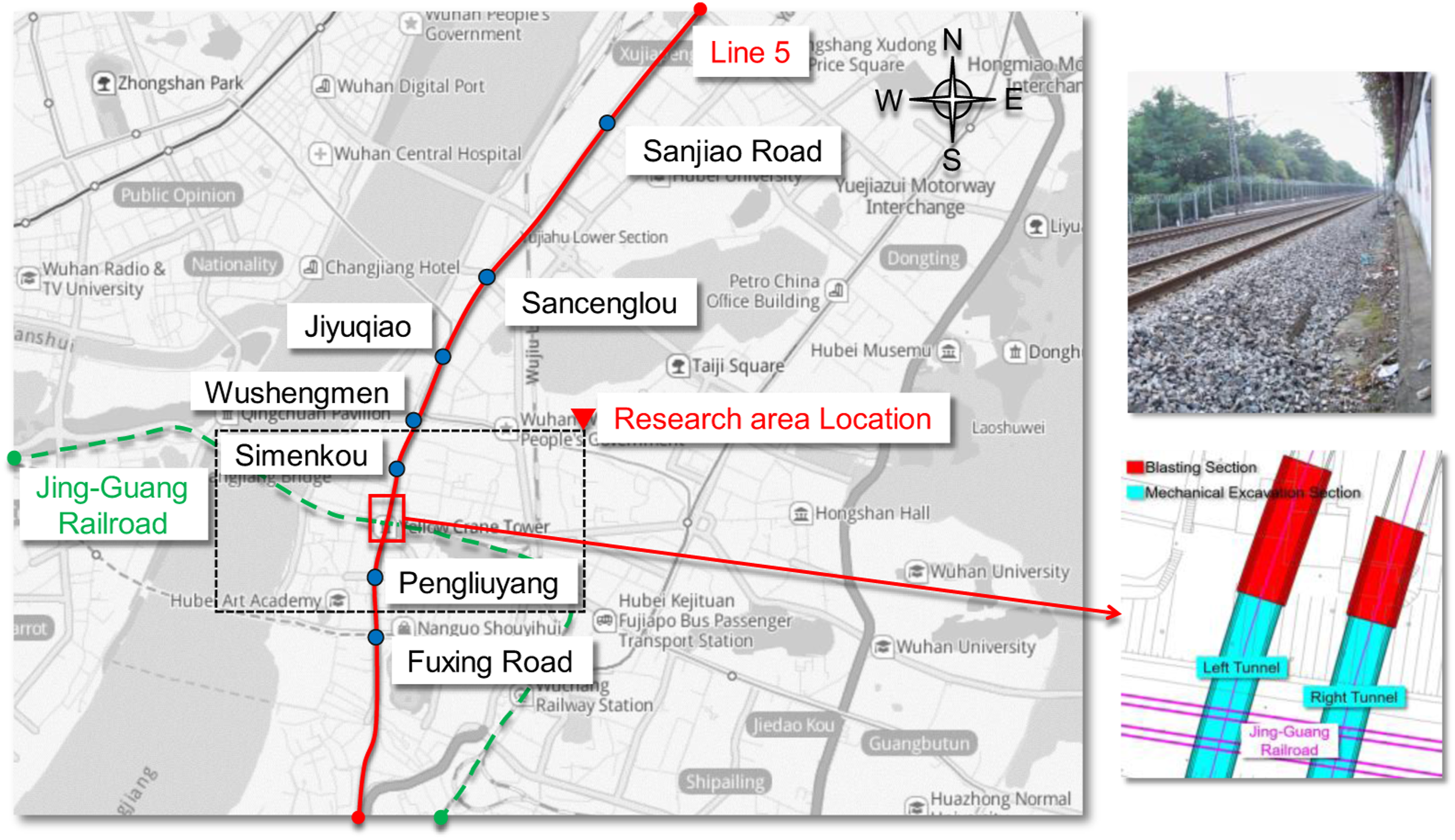
The railway protection range, which forbids blasting excavation, is 40 m on the left and right sides of the railroad, per the criteria of the railway authority. Within the protective zone, the mechanical disruption approach is utilized, whilst the blasting method is utilized beyond the zone. The distance between the top of the tunnel and the train bed is around 28.5 m, whereas the nearest explosion site is approximately 34.3 m away
To minimize the influence of blasting vibration on the above buildings. The bench cut method is adopted in the blasting construction. The three-stage wedge cutting blasting for upper steps and the first stage cut set 4 holes as a group that is named Cut holes 1, the second stage and third stage cut also set 4 holes as a group that are named Cut holes 2 and Cut hole 3. Each hole of Cut holes 2 is charged with a 1.85 kg explosive. The diameter of Cut holes 1, Cut holes 2 and Cut hole 3 are 40 mm and coupling charge mode is adopted. The Cut holes 2 group initiation is the maximum explosive of tunnel excavation blasting.
Field blasting vibration monitoring
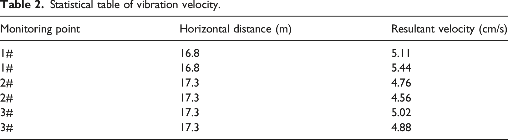
Transportation along the Zhengwu Section of the Beijing-Guangzhou Train is busy, and the railway must continue to operate throughout the blasting work. For reasons of safety and in accordance with the rules of railway authorities, blasting vibration monitoring points are not permitted within the usual operating range of trains. Therefore, monitoring engineers can only install monitoring sensors on the railway embankment and must vacate the railway line as quickly as possible following installation. Due to the limited carrying sensors and the inability to remain on the rail line for an extended period of time, only three blast vibration monitoring locations were established. The TC-4850 blasting vibration monitoring system is used for on-site monitoring of tunnel blasting construction. The monitoring system comprises sensors, a vibration detector, and software for Blasting Vibration Analysis. The device a three-dimensional vibration detector with a sampling frequency between 1 kHz and 50 kHz, which is precise and reliable. The engineers primarily monitored the vibration velocity of the railway embankment during tunnel blasting, and they positioned 1# monitoring point above the tunnel axis, 2# and 3# monitoring sites on both sides of the lining contour. During the right-line tunnel blasting excavation, two on-site blasting vibration monitorings were conducted on the top embankment, and six data groups were collected. The consequent peak velocity shows at monitoring point one#, 16.8 m from the explosion location, with a peak velocity of 5.44 cm/s. The layout of monitoring points is depicted in Figure 2, and the monitoring data are provided in Table 2. Monitoring point arrangement: (a) Location of monitoring points, (b) Monitoring equipment, (c) Field monitoring. Statistical table of vibration velocity.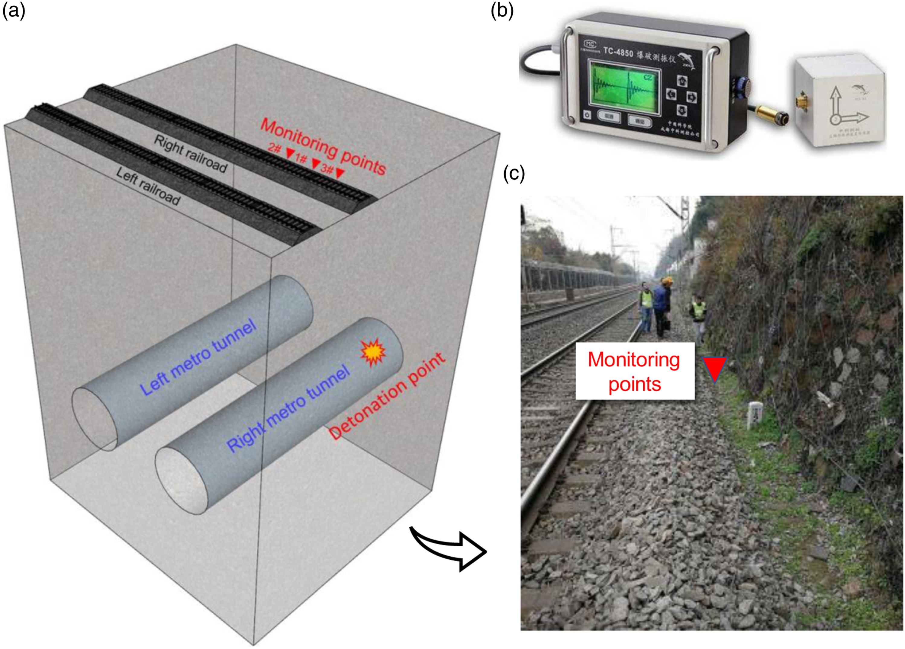
Numerical modeling and verification of ballast track
Calculation model of ballast rail- sleeper- truck bed composite structure
Due to the regulations of railway authorities, the vibration response data of the rail, sleeper, and railway rail bed structure cannot be gathered through on-site monitoring. To better examine the impact of subway tunnel blasting on railways, the ANSYS/LS-DYNA dynamic finite element software is used to develop a numerical model of subway tunnel blasting in order to examine the dynamic response of the ballast railway structures above. In accordance with the symmetry of the model, the model is chopped along the center axis of the right-line tunnel. It is only necessary to establish a 1/2 model and apply the symmetric constraint boundary conditions on the symmetric surface and the SPH_SYMMETRY_PLANE keyword (Groenenboom, 1997). The numerical model uses 8-node SOLID164 solid element with a scale of 1:1. The overall size of the model is 30.0 m × 61.7 m × 48.5 m, and the diameter of the tunnel excavation is 7 m. The rock mass, lining, explosive, track bed, and rail are divided into 945,451 units by LaGrange mesh, and the cm-g-μs unit system is adopted. In the study area, the stratum property is stable, and the terrain fluctuation is small. Therefore, the top surface of the model is set as a plane-free constraint boundary, and the other surfaces are all subject to the non-reflection boundary condition (Zhao et al., 2022).
It is well known that any dynamic finite-element prediction is dependent on the size and uniformity of the mesh refinement. According to Kuhlemeyer (Kuhlemeyer and Lysmer, 1973), 8–10 elements per wavelength are required to avoid any wave distortion. Therefore, the numerical model mesh density is determined to be 10 cm. For verifying the accuracy of the numerical calculation, mesh sensitivity analysis is performed with incorporation of finer mesh density of 5 cm and coarser mesh density of 25 cm, calculation results showed that the mesh density of 10 cm ensures the accuracy, and the calculation time is also with the acceptable range. cm-g-μs unit is adopted in the model. The numerical model size and boundary conditions are shown in Figure 3. Numerical calculation model.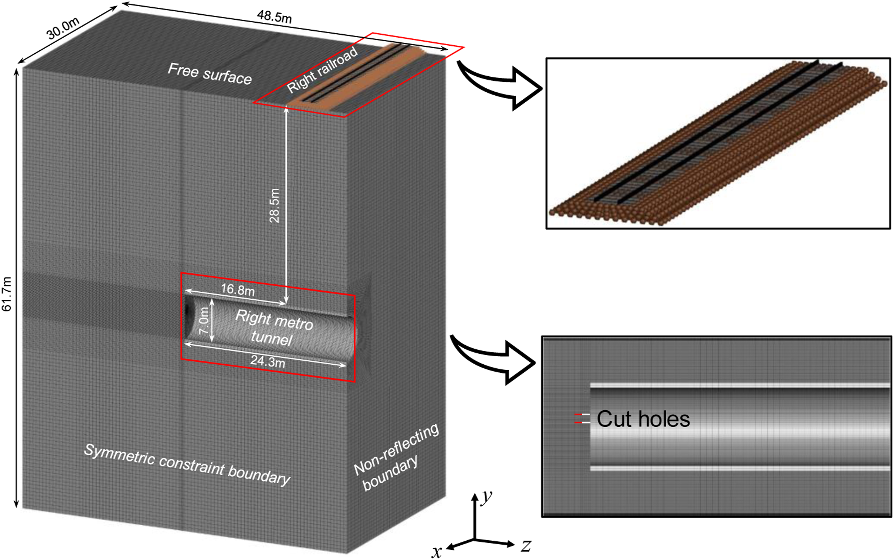
Rock mass material model
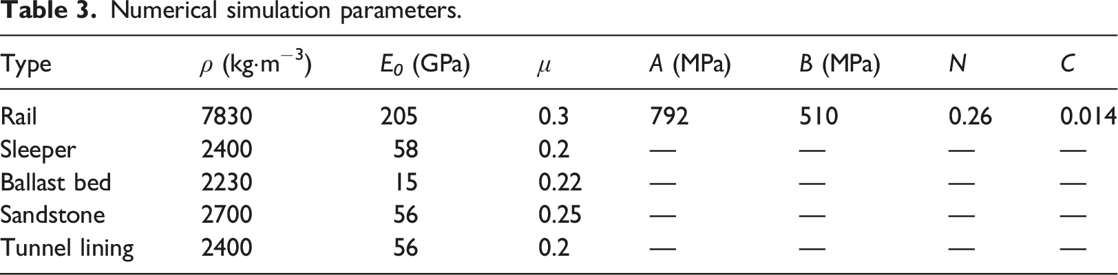
Numerical simulation parameters.
The stress-strain formula of *MAT_PLASTIC_KINEMATIC is as follow.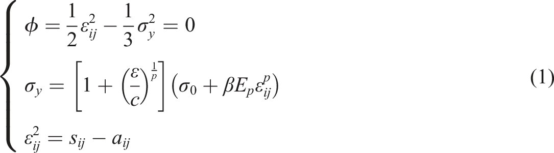
Ballast track material model
Indoor tests were conducted to determine the calculation’s appropriate parameters. The ballast bed is an essential component of the railway and serves as its foundation. The ballast bed material of the ballast track is graded crushed stone, which offers excellent support and buffering for the railway track. To better mimic the dynamic performance of the ballast bed and the granular state of graded gravel, the SPH (smoothed particle hydrodynamics) algorithm is used to create the ballast bed model. The SPH (smoothed particle hydrodynamics) approach overcomes not only the accuracy loss caused by mesh distortion in the LaGrange algorithm when substantial deformation occurs, but also the interface problem between the Euler mesh and the material in the Euler algorithm. Its core concept is to divide the issue domain into a finite number of particles, each of which has its own mass, density, and other physical qualities. The filling rate for the SPH element material mapping *MAT_PLASTIC_KINEMATICS material model is 120%. Between the embankment and the SPH element, graded gravel is heaped as the ballast bed material, and the ballast bed (SPH element) and the embankment are connected by non-rigid connections. Using the SPH method for modeling has several advantages. First, by tweaking the control parameters, the SPH model can be as precise as the FE model and produce the required damping effect. Second, Graded gravel ballast in the construction of vibrating, with loose and stacked morphological characteristics, the SPH elements can be a good simulation of this morphological characteristics. Last, under varied working conditions, when the blasting vibration is high, the ballast may create significant displacement, so rendering the rail above unusable. SPH elements can mimic displacement changes under such huge deformation more accurately.
Similarly, the sleeper and ballast bed (SPH element) are not rigidly connected. However, because the mass of rail, sleeper, and gravel ballast is large, the displacement sliding between them is not obvious. Therefore, *CONTACT_TIED_NODES_TO_SURFACE (Hu et al., 2015) contact algorithm is used between SPH element and sleeper and embankment. SPH element nodes move together with the constrained surface in this contact type. At the beginning of the simulation, the nearest primary segment of each node is located based on the orthogonal projection from the node to the primary segment. According to established standards, if the node is considered close to the main segment, then the node moves to the main surface; in this way, the initial geometry can be slightly changed without causing any stress. Therefore, this type of contact is more suitable for the contact definition of graded gravel ballast bed and other railway structures.
The rail and sleeper are joined through fasteners, and it is possible to mistakenly believe that the rail and sleeper are firm connections. Consequently, the OVERLAP command is used in the numerical model to set the rail and sleeper constructions as the common joint contact type. Figure 4 depicts the numerical model of the ballast track. Numerical calculation model of ballast track.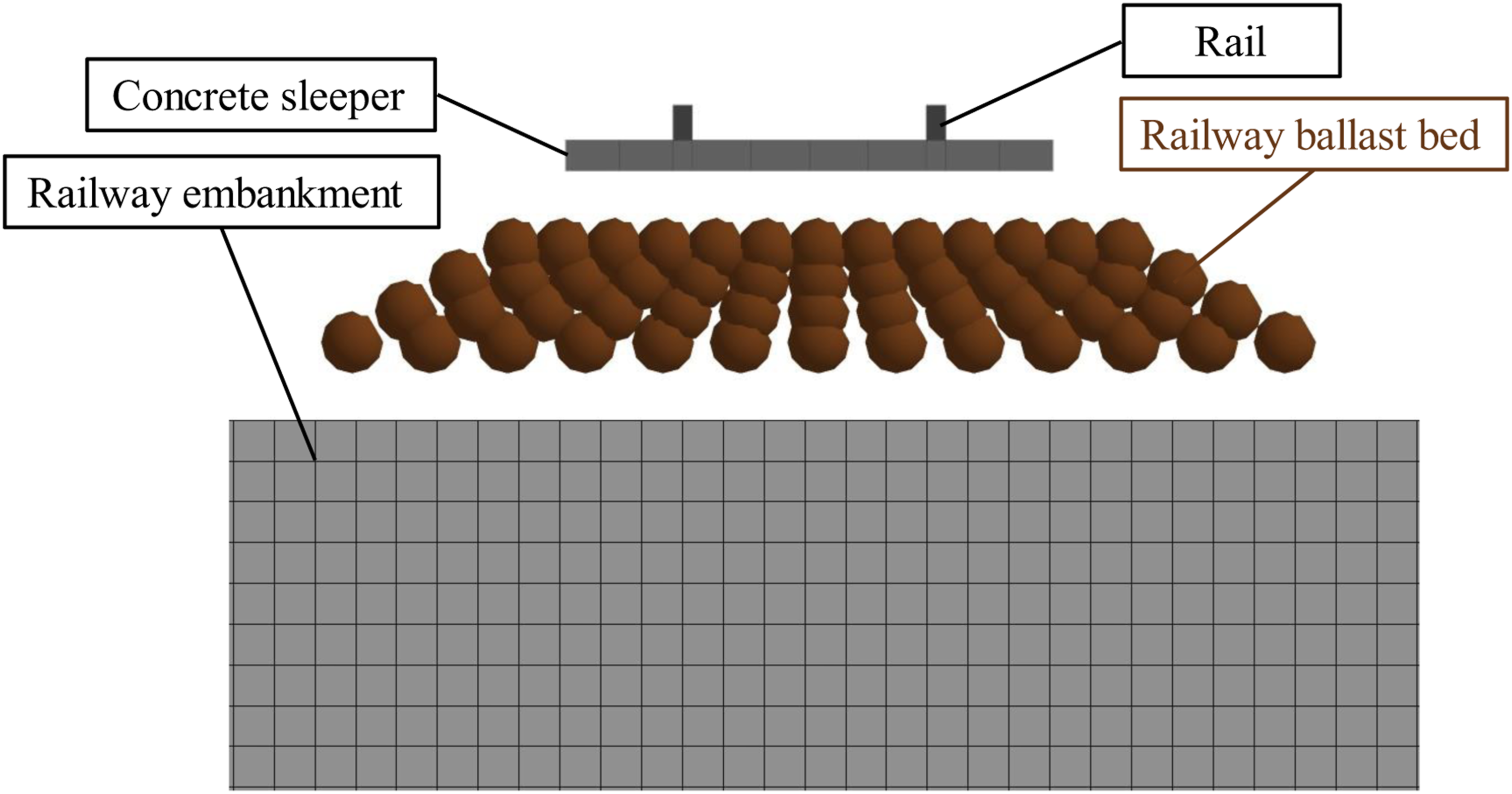
In the normal operation of the railway, the temperature change of the railway track is far from reaching the range that needs to consider the thermal softening and thermal deformation. Therefore, the *MAT_SIMPLIFIED_JOHNSON_COOK material model is selected to simulate the material model of the steel rail (Yao et al., 2018). The constitutive relationship formula is shown in formula (2).
To simplify the modeling process, the *MAT_PLASTIC_KINEMATIC material model is used to simulate the equivalent stiffness model of sleepers according to the method of equivalent modulus of reinforced concrete described by (Wang and Gong, 2018; Wu et al., 2022b). Material model parameters for rail, sleeper, and ballast bed (SPH element) as shown in Table 3
The tunnel lining is reinforced concrete material. According to the equivalent stiffness method mentioned above, *MAT_PLASTIC_KINEMATIC material model is also used to simulate the equivalent stiffness model of tunnel lining. The parameters of the lining material model are shown in Table 3.
Calculation model of blasting load

Explosive material parameters and state equation parameters.
Due to a lack of measurement instruments, the parameters for the JWL EoS were taken from Li et al. (Li and Ma, 2010) and Xie et al. (Xie et al., 2016), except for the density of the explosive, which is determined in the field test.
Model response to explosion loading
Numerical models to carry blasting loads have been studied by scholars (Anas et al., 2022d). In the Dyna software, the JWL equation of state has been adopted. The JWL EoS (equation of state) simulate the change in pressure and volume of the explosive gas. By using the created mesh as the calculation unit, the load transfer between meshes by means of co-nodes or contacts. Analyzing the stresses and deformations of the mesh cells under the action of explosives to reflect the influence of the overall model by blasting loads.
Analysis and verification of numerical results
In accordance with the blasting design document, as depicted in Figure 5, the cut holes 2 with a charge of 7.4 kg are the single maximum charge, and the model of the cut holes is depicted in Figure 6. Schematic diagram of the arrangement of blast holes in the upper bench. Cut holes model.
To verify the accuracy of the numerical model, according to the layout of the field monitoring points, the results of the same position of the particle in the numerical model calculation results are compared and studied to provide a reliable basis for the follow-up reference numerical model calculation results. The arrangement of monitoring points is shown in Figure 7. The numerical results of three vector combined vibration velocity of each monitoring point are compared with the field monitoring results; the results are shown in Table 5. Arrangement of monitoring points. Numerical and field monitoring peak vibration velocity.
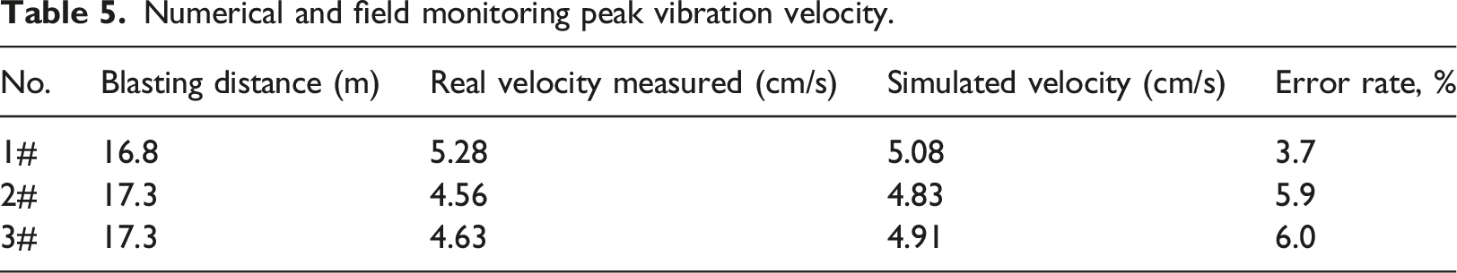
The peak vibration velocity of the monitored particle is slightly greater than that of the numerical simulation at the same place, as shown in Table 5. Maximum error is 6.0% and minimum error is 3.7%, which is below the 10% error control line. (Jiang et al., 2020). The vibration velocity in the X-axis and the resultant velocity at monitoring 3# are shown in Figure 8 and 9. The waveform of the actual monitoring of the X-axis and the resultant velocity is basically consistent with the waveform obtained by numerical simulation, and the attenuation law is also roughly the same. The peak value of vibration velocity at site monitoring points is slightly smaller than that of numerical calculation. However, the attenuation speed of numerical model is clearly faster than field monitoring. The reason is that there are various structural planes in the rock, which will affect the propagation and frequency attenuation of blasting stress wave. From the above analysis, the reliability of the numerical calculation model is verified, and the other components of the ballast track railway structure can be analyzed by this numerical calculation model. X-axis velocity comparison at 3# Resultant velocity comparison at 3#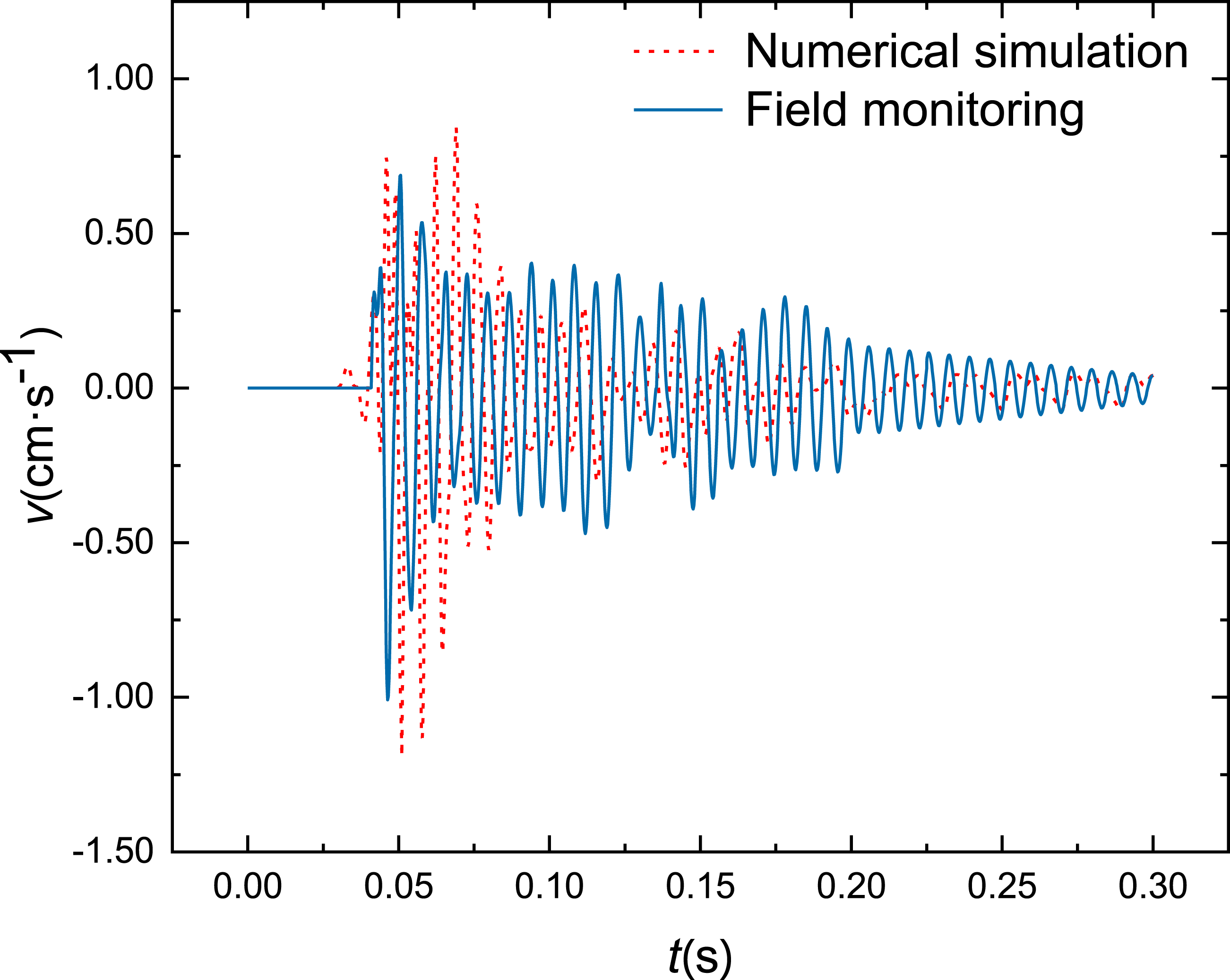
Dynamic response characteristics of ballast track structure under blasting vibration
Distribution characteristics of rail vibration velocity
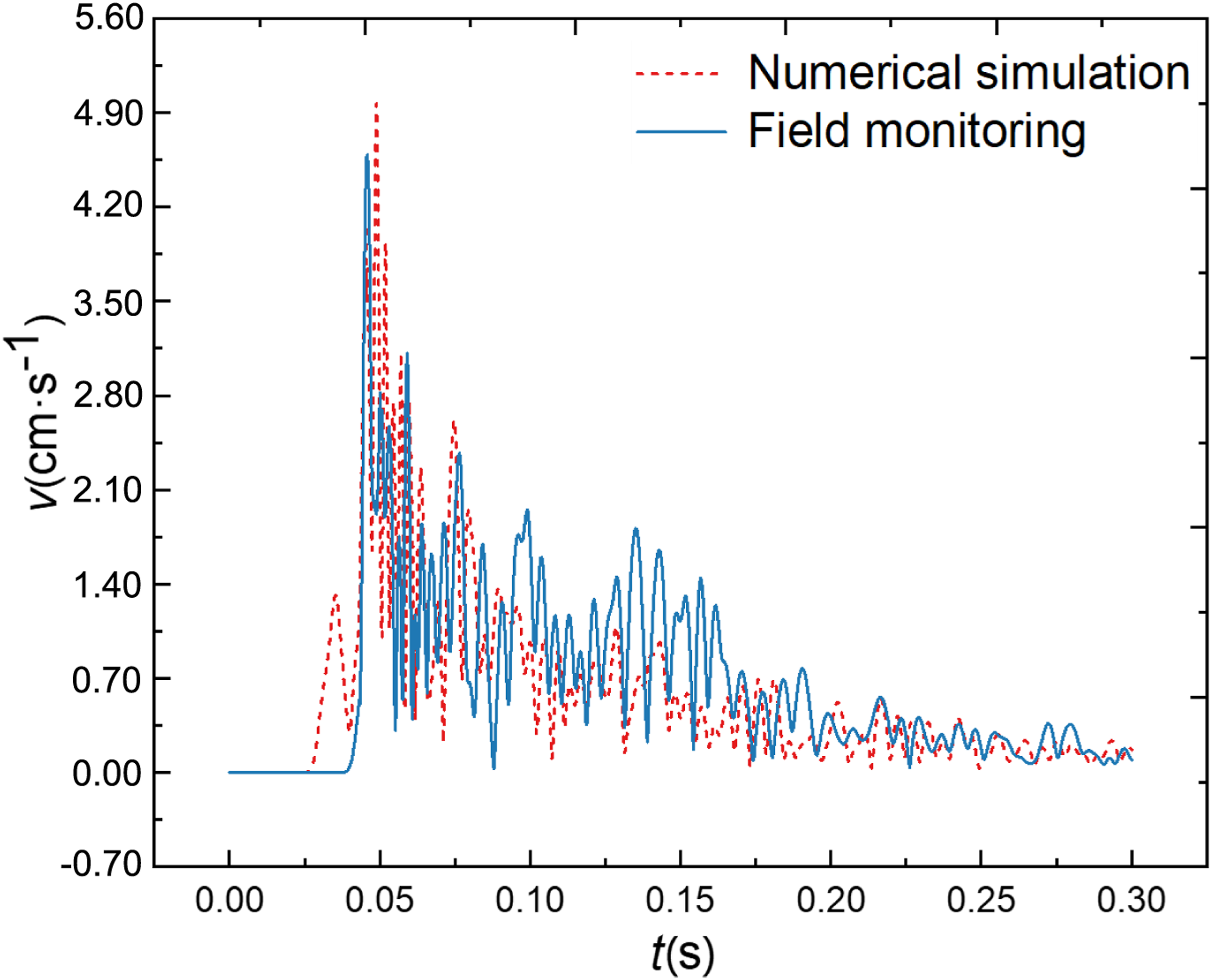
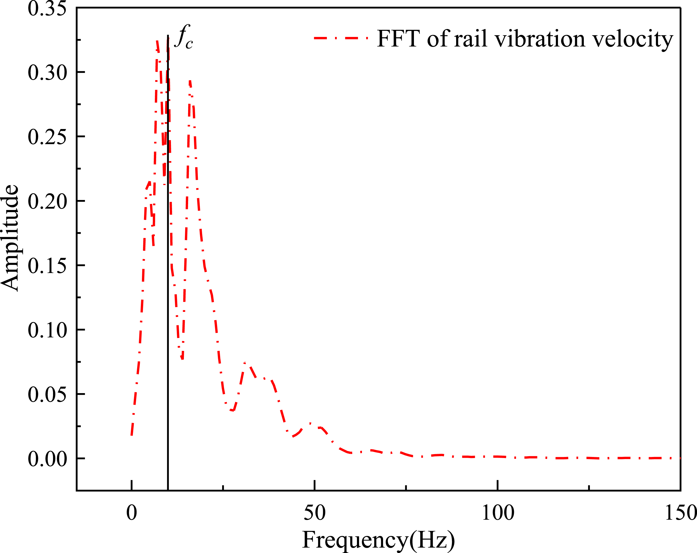
Due to safety considerations, only three monitoring points can be installed near the ballast bed on the embankment. According to the above-verified reliability numerical model, the most hazardous working conditions on the rail structure are selected in order to ensure the safety of the railways; specifically, the maximum explosive for tunnel excavation blasting is 7.4 kg. At a horizontal distance of 16.8 m from the explosion point to the rail, the particle is analyzed. Figure 10 is a diagram illustrating the rail’s vibration velocity. Figure 10 demonstrates that, under the most hazardous situations, the peak vibration velocity of the rail increases as the explosion source distance decreases. At a distance of 0.4 m, the rail’s highest vibration velocity is measured to be 0.409 cm/s. Simultaneously, the peak vibration velocity along the railway direction falls progressively, and the waveform is serrated. The reason for this is that the blasting vibration is communicated to the top rail through the sleeper, briefly increasing the rail’s peak vibration velocity. Simultaneously, the peak vibration velocity waveform gradually flattens away from the explosion source; the peak vibration velocity appears at 0.4 m as opposed to 0 m since 0.4 m is the contact point between the rail and the sleeper. The peak particle velocity (PPV) is generally used to evaluate the safety of blasting vibration of general buildings. Because the peak particle velocity (PPV) has a good correlation with the damage to the structures, the damage of the structure is closely related to the frequency of blasting vibration. (Singh and Roy, 2010) This research will therefore introduce the peak particle velocity in relation to frequency as the primary criterion for evaluating the safety of ballast railway systems. The peak particle vibration velocity of 0.409 cm/s was evaluated by Fourier transform (FFT) to generate the spectrum characteristic image depicted in Figure 11. The primary vibration frequency of the rail impacted by blasting is 9,98 Hz, as shown in Figure 11. The railway seismic code and earlier research indicate that the vibration frequency is less than 10 Hz, which has a significant impact on the safety of railway structures. Rail vibration velocity. Spectrum characteristics of rail.
Distribution characteristics of rail peak displacement
The excessive displacement of the rail may cause structural damage to the railway and compromise traffic safety. Analyzing the displacement of the rail under the action of the blasting is, thus, of considerable engineering importance. A number of unit monitoring locations are selected in the numerical model rail near the blast source, and the track structure displacement diagram is depicted in Figure 12. Comparative study of Figures 8 and 12 reveals that the distribution of rail displacement and vibration velocity are substantially comparable. For the rail, the displacement of the rail element diminishes gradually as the rail moves away from the explosive source, with the maximum displacement occurring above the rail. The rail’s maximum displacement is 0.095 cm. In some scholars’ studies (Lai and Jiang, 2022; Li and Conte, 2016), The maximum displacement of the rails under the action of the earthquake is 0.4 cm, and the rails remain in elastic deformation, with no substantial structural damage. Thus, in this instance the rails are safe under the influence of blasting vibration. Rail displacement.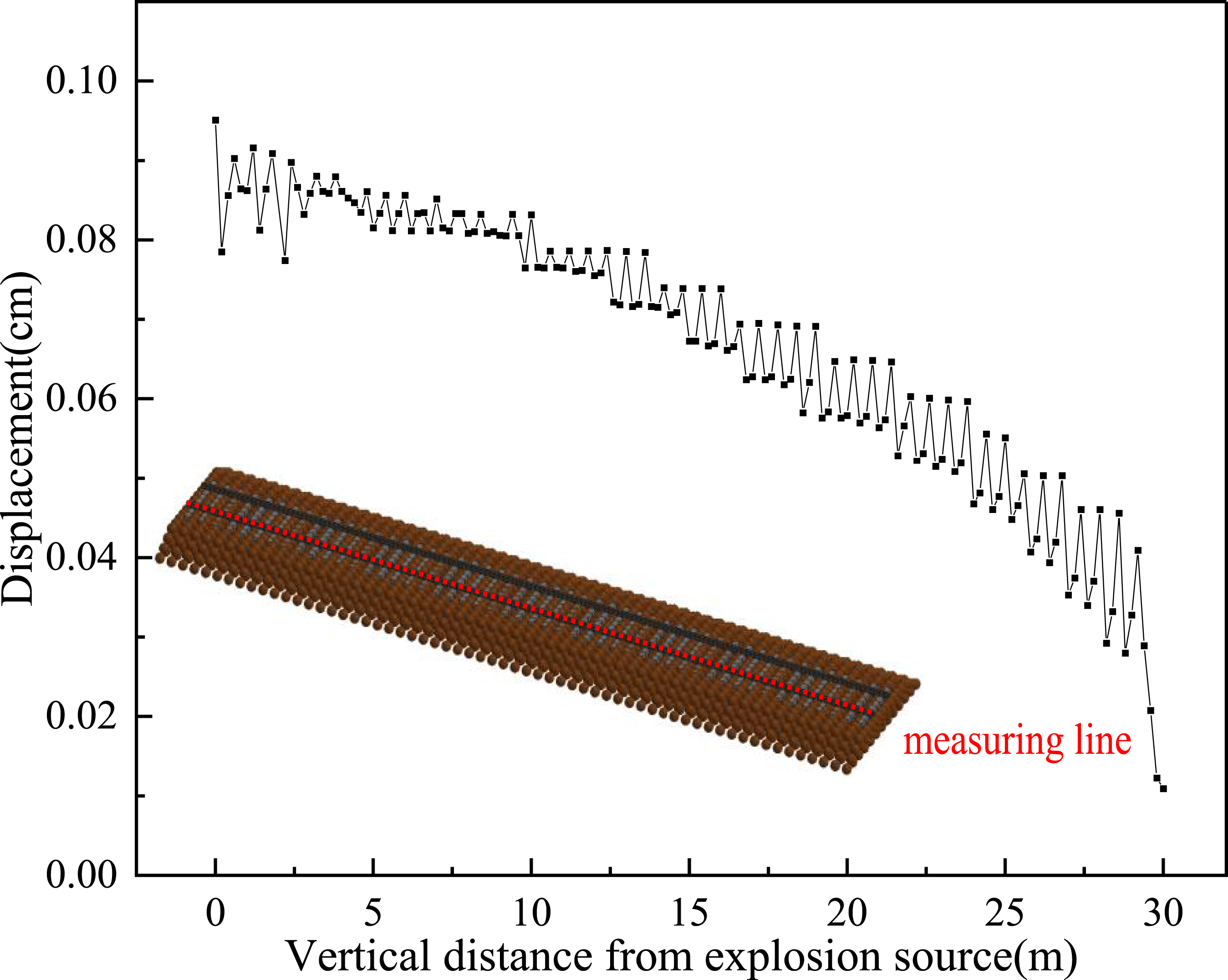
Distribution characteristics of ballast bed vibration velocity
The construction beneath the rail consists mostly of sleeper and ballast bed, with the rail and sleeper being fastened together. The dynamic response characteristics of the blast-exposed sleeper are comparable to the dynamic response characteristics of the rail structure. The ballast bed offers support and cushioning for the structure of the rails above. The structural integrity of the ballast bed will directly influence the overall safety of railroad tracks. To accurately simulate the impact of blasting vibration on the graded crushed stone ballast bed beneath the tunnel, the SPH method is utilized to simulate the ballast bed structures, and a number of unit monitoring sites are chosen along the railway line in the ballast bed unit (SPH). The ballast bed is separated into an upper half adjacent to the rail and a lower half adjacent to the embankment. Figure 13 depicts the vibration velocity diagram of the ballast bed structure’s upper and lower halves. Vibration velocity of the upper and lower ballast bed.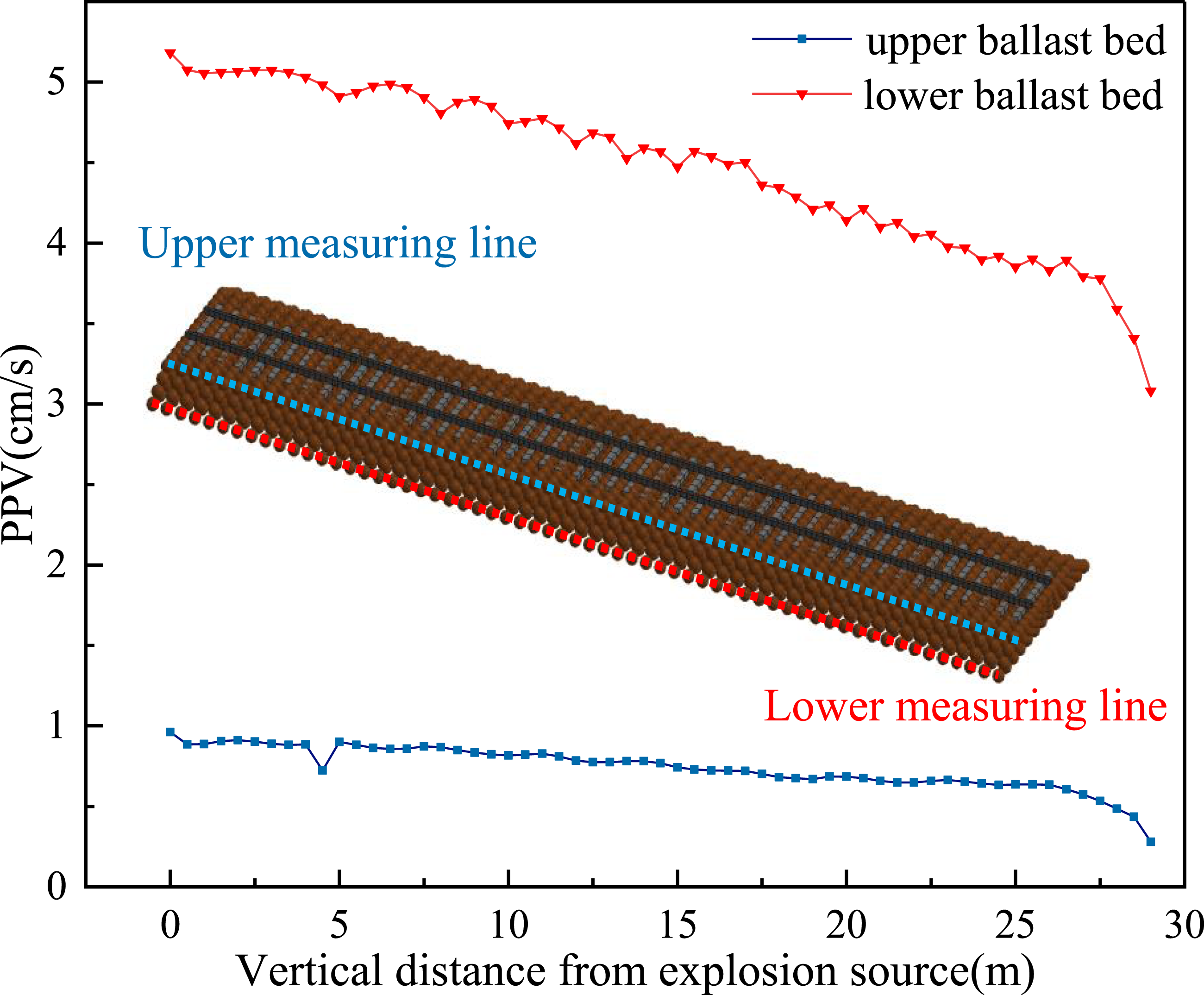
Figure 13 demonstrates that the peak vibration velocity of the ballast unit increases as the explosion source distance decreases, and that the distribution law of the vibration velocity is similar to that of the rail vibration velocity. The peak vibration velocity of the top ballast unit close to the upper explosion source is 0.96 cm/s, while that of the lower ballast unit is 5.18 cm/s, with an attenuation rate of 81.5%. At a transverse distance of 25 m, the transfer of blasting load has a noticeable boundary impact, hence the upper and lower ballast bed units at this distance are selected for vibration velocity analysis. At 25 m, the top ballast bed unit has a peak vibration velocity of 0.64 cm/s, the lower ballast bed unit has a peak vibration velocity of 3.78 cm/s, and the attenuation rate of vibration velocity is 83.1%. The variation in vibration velocity between the upper and lower ballast beds is significant. The reason could be that the discrete structure of graded crushed stone ballast bed has an excellent blocking effect on vibration transmission, so reducing the strong vibration velocity of the lower blasting to a safe level. Similarly, the attenuation rates of the upper and lower vibration velocities from the proximal and distal ends of the blasting source are essentially identical. The reason is that the particle size of graded ballast is consistently distributed in 20 mm–60 mm, the gradation is poor, and the particle size difference is modest, which provides a good transverse and longitudinal resistance for the train operation above and the vibration transmission below. Therefore, the vibration attenuation is relatively consistent in all portions of the ballast rail line. For the assessment of the ballast bed’s safety, the incorporation of vibration frequency is also crucial. Figure 14 depicts the spectrum characteristics generated by Fourier transform (FFT) of the particle vibration curves of the upper and lower ballast beds close to the explosion source. Figure 14 reveals that the primary vibration frequency of the upper and lower ballast beds is 9.98 Hz, which is compatible with the upper rail’s vibration frequency. Spectrum characteristics of the upper and lower ballast bed.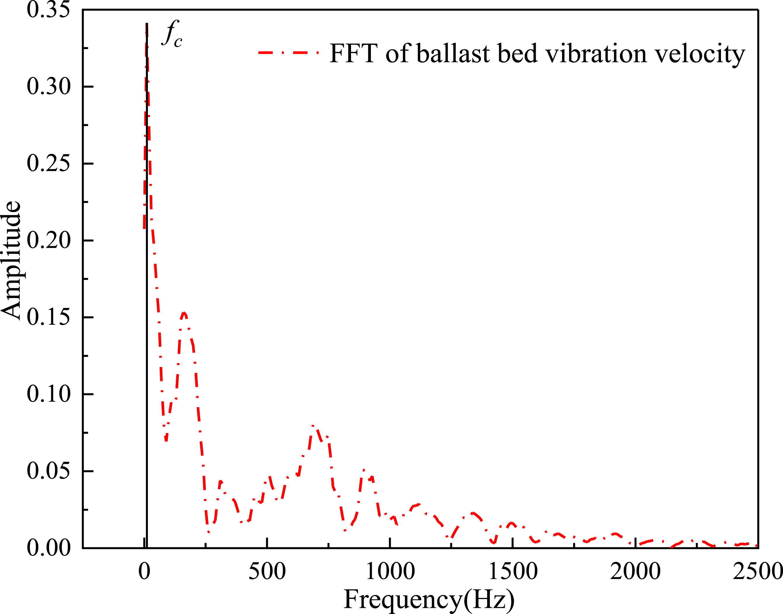
Safety evaluation of ballast railway under blasting vibration
Based on the safety standard of railway ballast bed vibration velocity
The particle vibration velocity is a crucial signal for determining whether or not a structure has been compromised. The forecast and regulation of its value are crucial for blasting engineering’s construction and safety control. At the same time, the vibration frequency and vibration velocity are typically used as evaluation indices in China’s existing blasting vibration safety requirements. Considering the uniqueness of railway facility safety, the China Railway Administration has clearly outlined the safety control rules for blasting vibration of railway infrastructure in (CRA, 2019):
Allowable safety standard of blasting vibration.
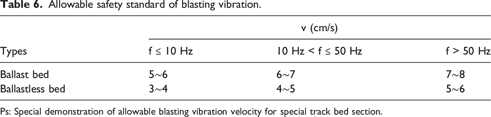
Ps: Special demonstration of allowable blasting vibration velocity for special track bed section.
Based on the rail peak displacement at the most dangerous critical speed of train operation
The vibration control threshold of the ballast bed has been stipulated in China National Standard, but it lacks the safety control threshold of rail vibration velocity. By establishing the relationship between vibration velocity and displacement of rail, the author puts forward the safety control vibration velocity of rail under tunnel blasting. Under the action of blasting below, the vibration velocity and displacement of the longitudinal (y-direction) of the rail are significantly greater than the vibration velocity and displacement of the x-direction and z-direction. At the same time, the longitudinal displacement of the rail is also an important factor affecting the stability of the train. The change of the displacement in the y-direction can determine whether the train is affected by the blasting vibration. The blasting side rail is selected as the analysis object. A certain number of monitoring points are selected in the model to draw the relationship between peak vibration velocity and displacement, as shown in Figure 15. Relationship between track vibration velocity and displacement.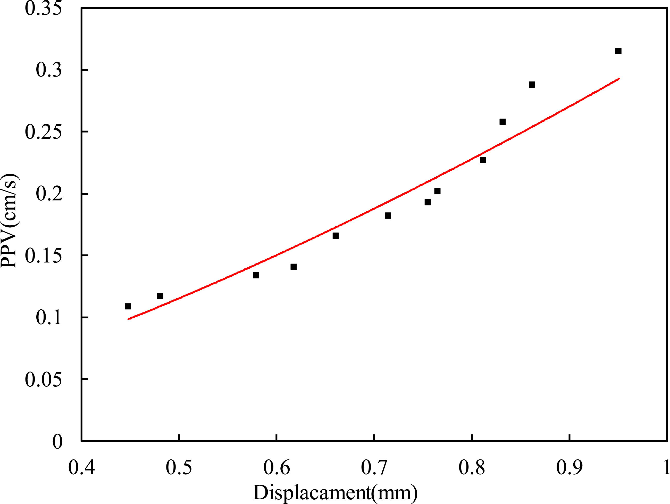
The Figure 15 shows that the peak vibration velocity in the y-direction of the rail is a power function relationship with the corresponding displacement, and the fitting degree is 0.9458. It shows that the peak vibration velocity in the y-direction of the rail has a high correlation with the corresponding displacement. The relationship equation is:
Equation (4) is derived by fitting the case’s engineering characteristics, and it has a high degree of confidence in predicting the vibration speed and displacement of the rail in this project. Nonetheless, this relationship will be influenced by a number of factors, the most significant of which is the principal vibration frequency of seismic waves, which is determined by the elastic modulus of the material model; consequently, this paper performs parameter calculations for the elastic model of the material under different lithologies. The calculation results of different elastic models are shown in Figure 16. Calculation results of different elastic models.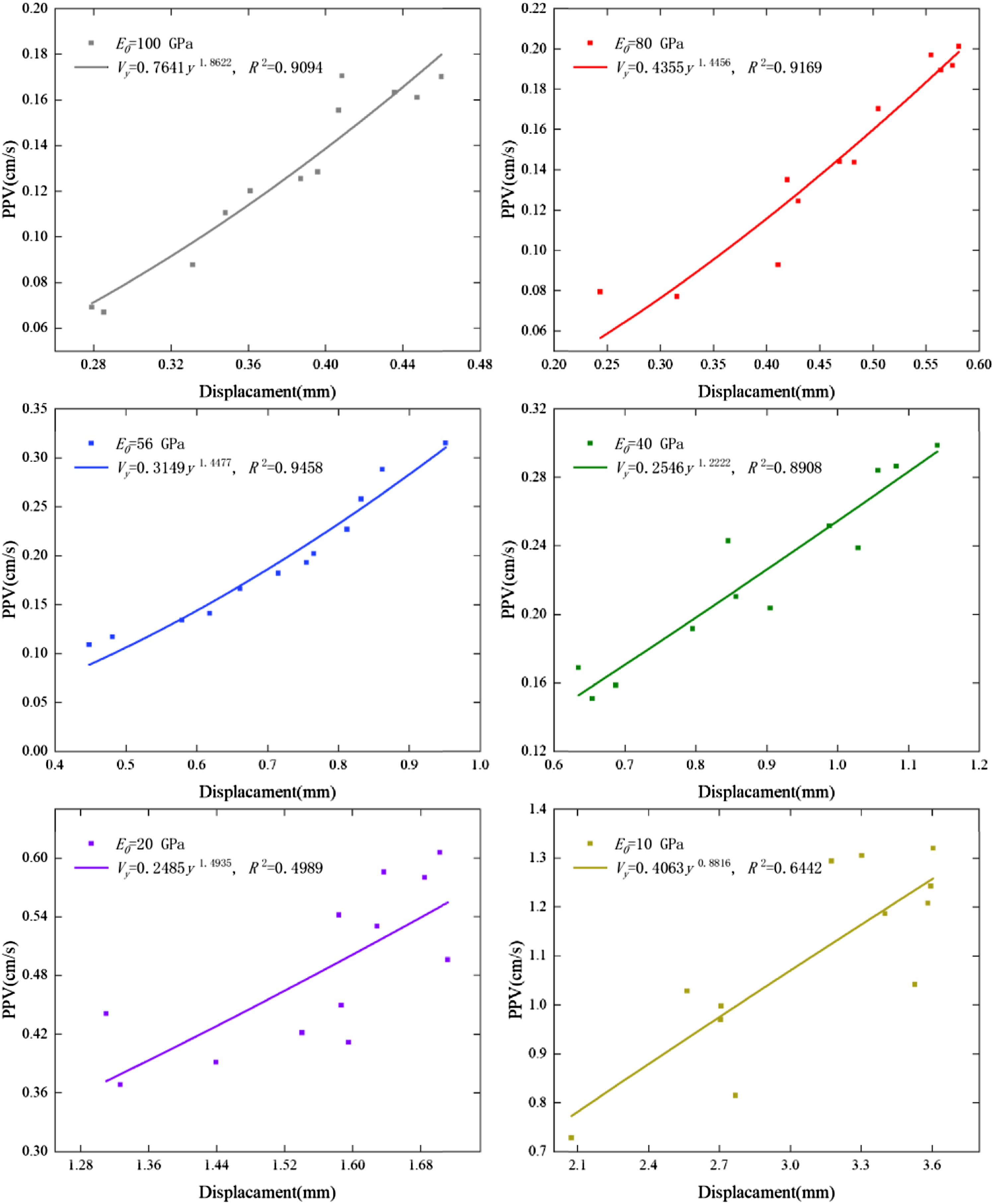
Under various elastic modes, the relationship between the vibration speed and displacement of the rail is as follows.


The above equation may be used to forecast the displacement by rail vibration velocity under different lithologies, and the following approach can be used to calculate the control vibration velocity of rail under different lithologies. Figure 16 reveals, however, that when the elastic modulus of rock model is greater, the fit of equation (4)–(7) is higher and the applicability and usefulness are enhanced, whereas when the elastic modulus of rock model is less than 40 GPa, the fit of equation (8) and (9) is lower and the applicability and usefulness are diminished. This effect may be caused by the fact that when the elastic modulus of the rock is low, the rock’s quality is poor, the transmission of stress is poor, and the propagation of seismic waves in this rock will experience a greater attenuation.
Combine the six aforementioned conditions of the vibration velocity and displacement relationship graph, as shown in Figure 17: the greater the elastic modulus, the smaller the vibration velocity and displacement, and the better the equation fit; conversely, the smaller the elastic modulus, the greater the vibration velocity and displacement, and the worse the equation fit. Combine results of different elastic models.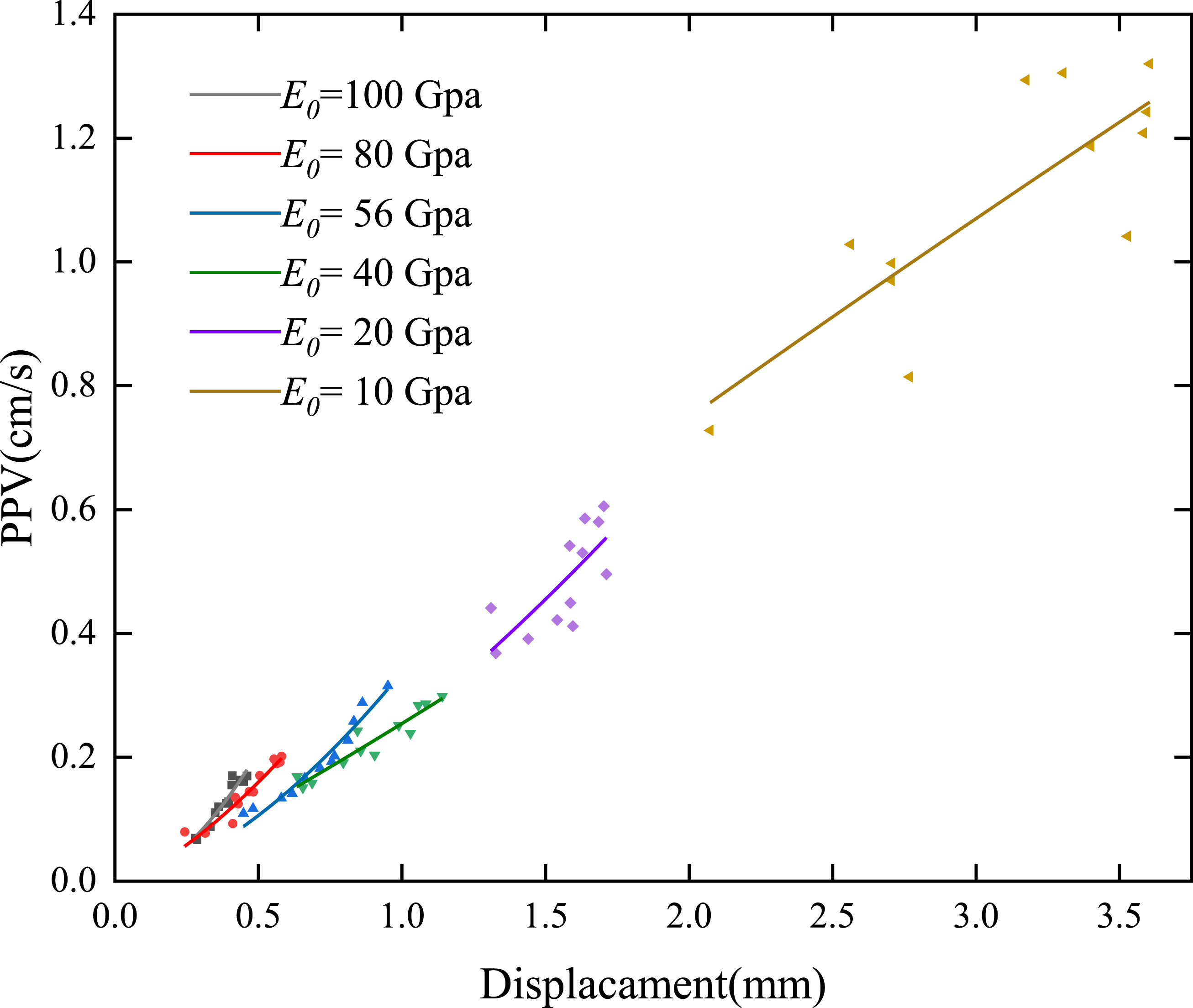
Because of the following reasons, the simplified model that is shown below can be used to determine the displacement of the rail in the limit situation, and the relationship between rail displacement and vibration velocity can be determined by referring to the previous section of this article. First, rail displacement on ballasted railroads is an essential component that restricts the operating speed of ballasted railroad trains, among the many factors that limit the maximum speed of train operation. If the displacement of the rail and sleeper is too great, it will put the train in danger of derailing; hence, the displacement of the rail is an important indicator to consider when determining whether or not the railway structure is safe. Second, the purpose of this simplified model is to compute the displacement of the rail at extremely high speeds, which are already higher than the operational speeds of high-speed rail in the majority of countries throughout the world. Third, Rail displacements caused by train operation and rail displacements caused by blast vibration both have a major effect in the Y direction. Last, this method is an attempted calculation method, the proposed control threshold is small, and the actual project will be safer.
Consequently, based on the available research (Jones et al., 1998; Sheng et al., 1999), the rail was modeled as a semi-infinite Euler beam and placed on a Kelvin base. In the meantime, simply harmonic loads (F) are applied to a semi-infinite Euler beam with equivalent train loads in order to determine the maximum deflection of a semi-infinite Euler beam under limited train speed and limited load conditions. This simplified track system model takes into account elements such as load distribution, rail stiffness, foundation stiffness, and foundation damping, which is advantageous for assessing rail dynamics characteristics. The reduced track system model depicted in Figure 18 has been adopted. Simplified track system model.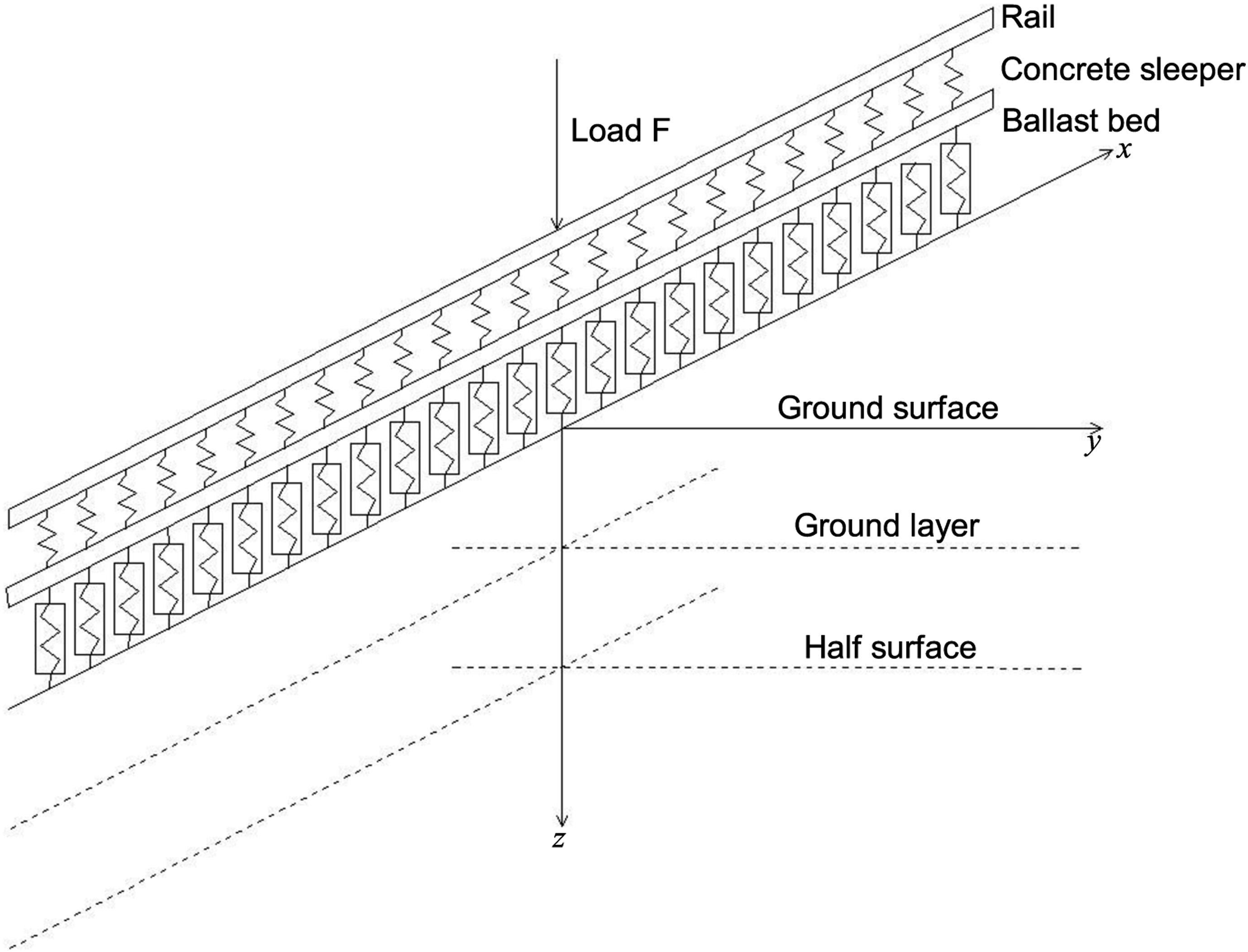
In the track system model, the train load is regarded as a simple harmonic load, the load F moves along the x-direction, and the rail is a continuous supported Euler beam. The Equation of motion shows is equation (10).
Equation (11) is obtained by two-dimensional Fourier transform on x
1
, t of the equation (10).
The equation (11) is an algebraic equation of deflection in the transform domain, which can be solved equation (12).
Replacing the original coordinate system with the coordinate system of synchronous motion with load: 
calculating parameters.
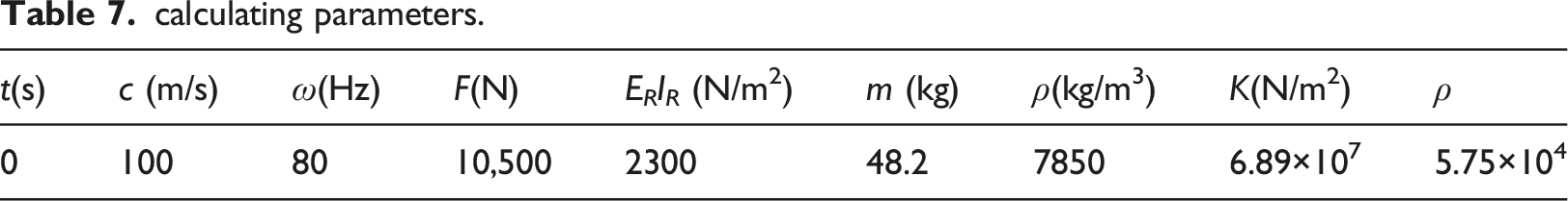
Substituting the calculation parameters in Table 7. into equation (13) and only under the action of the harmonic load, when the train speed reaches 100 m/s, which is a dangerous critical speed. Currently, the peak displacement of the rail is about 6.65 mm. By substituting the peak displacement of the rail at the most dangerous critical speed of train operation into the equation (4). Eventually, the limit control vibration velocity of the rail under blasting action is 8.22 cm/s.
Conclusion
Combining field monitoring with dynamic finite element numerical modeling, this research analyzes and investigates the blasting vibration response characteristics of the rail and ballast bed. The examination of safety is conducted for the most hazardous working situations. The key findings are as follows: a. The numerical calculation model is fundamentally consistent with the vibration law shown in the field monitoring data, and the error is minimal. The rail and ballast bed’s peak vibration velocity increases as the distance from the explosion source decreases. b. Loosely graded crushed stone is used in ballast rail bed, which has a strong vibration-blocking effect. The strong vibration velocity of the lower blasting is reduced to a safe range, and the attenuation rate of the upper and lower vibration velocity from the proximal and distal blasting source is essentially identical. Modeling ballast using the SPH element method accurately simulates its true vibration damping effect. c. The relationship between rail vibration velocity and displacement can be determined via parameter computation, where a larger elastic modulus of the rock results in a better-fitting equation and a smaller elastic modulus results in a less-fitting equation. The maximum displacement of the rail, as predicted by the simplified model, can be used to compute the rail’s vibration velocity in the most hazardous circumstance. d. By analyzing the numerical model. The blast control velocity of ballast railway structures needs to be completed in the relevant design codes. The method proposed in this case study can be used as a reference option for assessing the safety of ballast railway structures subject to blast disturbance until the relevant specifications are improved, but specific parameters need to be considered depending on various construction condition.
Footnotes
Declaration of conflicting interests
The author(s) declared no potential conflicts of interest with respect to the research, authorship, and/or publication of this article.
Funding
The author(s) disclosed receipt of the following financial support for the research, authorship, and/or publication of this article: This study was sponsored by the National Natural Science Foundation of China (Grant No. 41807265, 41972286, 42072309) and Hubei Key Laboratory of Blasting Engineering Open Fund project (HKLBEF202001, HKLBEF202002).