
Abstract
Obstacles arranged into a pre-fractal shape (Sierpinski carpet) were tested for their blast attenuation abilities using 250 g PE4 at three different scaled distances (Z = 1.87, 2.24, 2.99 m/kg1/3). Three pre-fractal iterations were tested, as well as free-field tests for comparative purposes. Reductions in peak overpressure up to 26% and peak specific impulse up to 19% were observed, attributed to a mechanism known as ‘trapping’. This mechanism is characterised by a reduction in the ability of a blast wave to advect downstream, with corresponding increases in pressure observed within the bounds of the pre-fractal obstacle. Attenuation magnitudes and areas of reduced pressure and impulse were found to be drastically different with each pre-fractal iteration, with a transition from shadowing to wave trapping as the obstacles more closely resembled true fractals. A linear dependence on a newly-defined obstruction factor (OF) was found for arrival time, overpressure and impulse at the sensor locations, suggesting that the attenuation of a pre-fractal obstacle is inherently determinable. The results indicate that the mechanism of blast mitigation of pre-fractal obstacles is fundamentally different from singular or arrays of regular obstacles, and could be exploited further to develop novel protective structures with enhanced blast attenuation.
Introduction
Context
There is a clear and pressing need to protect civilians and infrastructure against the damaging effects of explosions, either intentional (e.g. terrorist attacks) or accidental (e.g. the 2020 Port of Beirut explosion Rigby et al., 2020). One such measure is through the use of engineered protective structures. Typically these are formed of hardened, monolithic barriers (Smith, 2010); however, recently a new type of blast wall has been proposed (Asprone et al., 2015), termed a ‘fence-type’ blast wall. Fence-type blast walls are formed using an array of smaller obstacles and aim to match the mitigation properties of a monolithic blast wall with substantially reduced structural weight and enhanced portability (Hao et al., 2017). The unimposing aesthetics of such a ‘wall’, the aforementioned reduced structural material and potential portability/temporary nature, make them appealing choices for ‘softer’ blast mitigation strategies in urban environments.
Gebbeken et al. (2017) and Warnstedt and Gebbeken (2020) extended this concept by proposing the use of plants and hedges to construct a natural fence-type blast wall. This concept was further studied by Gajewski et al. (2022). In the immediate shadow region of the plants (0.5H, where H is obstacle height), attenuation in the order of 40% was reported. It is particularly noteworthy that coniferous (thuja) plants resulted in a reduced magnitude and flat-topped pressure profile, whereas cherry laurel hedges exhibited a more typical exponential decay behind the plants. It is clear therefore that not only does the presence of an obstacle result in downstream mitigation, but the type of obstacle has significant influence also. Specifically, the enhanced mitigation of the coniferous plants is hypothesised to be due to their multi-scale nature (i.e. the presence of many smaller scale substructures within the obstacle, compared to the cherry laurel leaves which are all of similar size).
Scientific motivation
Multi-scale, self-similar structures are prominent in nature – trees, ferns, clouds, coastlines, shells. As mentioned previously, self-similarity is hypothesised to have contributed to the observed blast mitigation behaviour of plants and hedges. This paper aims at studying this further by experimentally investigating the blast mitigation behaviour of self-similar structures. Whilst the findings are aimed at better understanding the performance of natural fence-type blast barriers, the true influence of self-similarity must first be studied in isolation.
Fractals are mathematically self-similar structures, and are formed as an infinitely-repeating pattern of a given starting shape (see Figure 1), hence the term self-similarity. It should be stated that fractals are not simply a pure mathematical concept; they have been successfully implemented in various engineering fields such as antennae, industrial mixing and heat exchangers. Fractals exhibit many favourable characteristics for these applications, such as (1) their scale similarity (Sreenivasan, 1991; Turcotte, 1988), (2) the presence of multiple length scales (Higham and Brevis, 2018; Higham et al., 2021; Higham and Vaidheeswaran, 2022) and (3) their higher surface area per unit volume (Werner and Ganguly, 2003). All these characteristics make fractals potentially suitable candidates for efficient blast mitigation in the urban environment. An illustration showing the first three iterations of the Sierpinski carpet. The colours used to represent each pre-fractal shape, and the markers under each shape, are used to represent data pertaining to these obstacles in all results figures reported in this article unless where specifically noted. The dimensions of the pre-fractal shapes used in this work may be found in Table 1.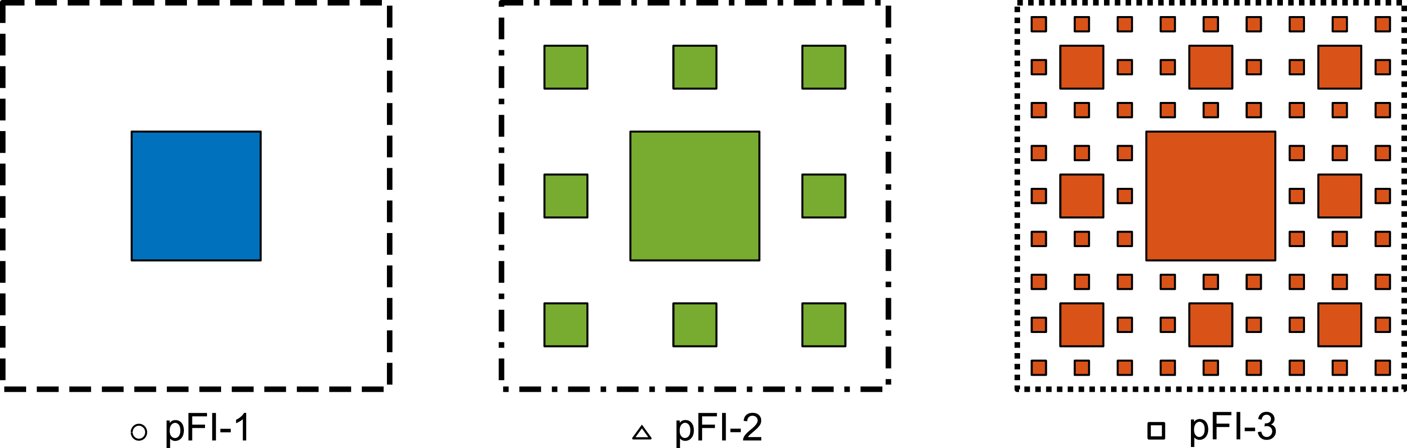
Since a fractal is a pattern that repeats infinitely, it is not possible to achieve a true fractal in real life, and only a finite number of iterations of self-similarity can be practically achieved. Such intermediate shapes are called ‘pre-fractals’. Therefore, this study is aimed at investigating the interaction of blast waves with pre-fractal obstacles.
The paper is organised in the following manner. First motivations for the choice of a fractal are discussed. Next, the experimental methodology is described and the experimental results are presented in detail, typically with reference to baseline free-field data at select sensor locations. Following this, an engineering model to predict pressures in the vicinity of the obstacle, using an equivalent blockage factor, is presented.
Fractal design requirements
For conventional geometric shapes, a straight line equally partitioned into two units, an area (square) split into two equal parts along each dimension or a volume (cube) divided into two equal portions along each dimension would lead to 21, 22 and 23 identical units each, with the exponents here referring to the ‘dimensions’ of the original object. However, for a 2D fractal, this dimension is usually more than two, and for a 3D fractal, it is more than three, as fractal shapes have an effectively infinite surface area in a finite volume. This relationship between surface area and volume is a key fractal characteristic which, it is posited, will lead to enhanced blast mitigation.
To help identify the most appropriate self-repeating shape, the following observations were made based in a review of relevant literature (Isaac et al., 2022): Lower porosity or a high blockage factor is the key contributor to blast mitigation (Chaudhuri et al., 2013; Dosanjh, 1956; Epstein and Kudryavtsev, 2012; Monti, 1970; Xiao et al., 2017). A flat frontal area of an obstacle is more effective (at mitigating loading) than a curved or pointed obstacle shape (Chaudhuri et al., 2013) Within the obstacle, a volume decrease followed by an increase along the blast wave transmission path enhances attenuation (Zong et al., 2017). As the phenomenon of diffraction helps weaken the incident blast wave, the presence of edges is possibly useful. This can also increase the possibility of vortex formation which has a potential for further attenuation (Prasanna Kumar et al., 2018; Suzuki et al., 2000). Increasing the number of rows can enhance attenuation but this has not yet been fully clarified in the literature (Jin et al., 2019).
The Sierpinski carpet, the first three iterations of which are shown on plan in Figure 1, satisfies the above criteria. Namely, the blockage factors vary for each iteration; the obstacles are flat-fronted and formed into rows; diffraction waves can arise due to the presence of multiple corners, and; voids between the obstacles may be considered as converging-diverging volumes. Furthermore, the pre-fractal is simple to fabricate since it is a vertical extrusion of this 2D pattern (i.e. shown on plan in Figure 1), and therefore, it can be made from standard square sections.
Experimental work
Overview
250 g PE4 was used as the explosive for all the tests. The pre-fractal obstacles were fixed onto a concrete ground slab and placed in front of a nominally rigid blockwork wall whose dimensions extend sufficiently in the horizontal and vertical directions such that clearing from its edges can be neglected (Rigby et al., 2014a). This blockwork wall may be taken to represent the structure being protected by the obstacle. The experiments were carried out on three iterations of a Sierpinski carpet-based fractal: pFI-1, pFI-2, pFI-3 (see Figure 1). A case without any obstacle (pFI-0) was also tested to obtain the reference free-field parameters.
For each iteration, experiments were conducted with the explosives placed at three different stand-off distances, 1.25 m, 1.5 m and 2 m, measured from the front face of the central obstacle. To reduce the likelihood of the fireball impinging on the target whilst still aiming to maximise the strength of the incident shock, 1 the closest stand-off distance (SoD) was set at 1.25 m giving a Hopkinson-Cranz scaled distance of 1.87 m/kg1/3, assuming a TNT equivalence of PE4 of 1.20 after Rigby and Sielicki (2014). The other two distances were selected to approximately represent mid-field and far-field scenarios (Hopkinson-Cranz scaled distances of 2.24 and 2.99 m/kg1/3, respectively).
In this work, for ease of reference, these stand-off distances have been termed as SoD125, SoD150 and SoD200. Triplicates were performed for each experimental condition (4 obstacle iterations including iteration zero, 3 SoDs each, plus two additional repeats to account for data drop-out); therefore, 38 experiments were conducted in total.
Experimental set-up
Obstacle design
Using a 180 mm square hollow section as the central obstacle for the first fractal iteration (pFI-1) in the Sierspinki carpet, the second iteration (pFI-2) incorporated eight 60 mm square pipes around the 180 mm square section. The third iteration (pFI-3) had eight 20 mm square rods surrounding each 60 mm square pipe from the previous iteration. This corresponds to a fractal dimension, D = log(N)/log(S) = 1.89, where N is the number of copies of the original on each iteration (N = 8), and S is the scale factor between an original and its copy (S = 3). There was a 60 mm air gap between the 180 mm and 60 mm obstacles, and a 20 mm air gap between the 60 mm and 20 mm obstacles, maintaining self-similarity. All obstacles were 1 m high.
A summary of obstacle types employed in this study and their geometric properties.

The obstacles were rigidly bolted onto tapped holes on a thick metal baseplate (650 × 650 × 25 mm). This baseplate was in turn held against the concrete pad using threaded rods that were chemically anchored to the ground. Prior to this, the concrete pad was cut out and filled up with screed to ensure that the baseplate would be flush with the rest of the pad once in situ. Three (thin) square alignment plates with appropriately sized cut-outs were positioned at approximately (1) 330 mm and (2) 670 mm above the floor, and (3) at the top of the obstacle assembly. Each plate was then tack welded to the square pipes at certain spots to maintain the alignment of each configuration with respect to the central obstacle. These tack welded plates also served to add to the stiffness of the overall structure and restrict deformation. All the square pipes had cover plates rigidly fixed on the top to prevent ingress of the blast wave.
The 180 mm square section had two cut-outs on the rear face – one at mid-height, and one near the bottom – for access to the central sensor mounting pad on the front face, and to fasten the mounting bolts, respectively. The cut-outs were then closed with flush mounted cover plates. The 60 mm pipes also had a cut out at the bottom, on the rear face, to access the fastening nuts that were used to hold them down against the heavy baseplate. These cut-outs were also flush closed with suitable cover plates. The 20 mm square rods were fully welded as a set of eight on a small baseplate and these sets were fastened onto the heavy baseplate using bolts on the periphery of each small baseplate. These bolt heads, however, could not be installed fully flush and they had to be left protruding out. The head being only 10 mm thick, the protrusion is negligible in comparison to the overall size of the obstacles. The alignment plates, used for pFI-2 and pFI-3 are also comparatively thin (5 mm and 3 mm) and parallel to the direction of blast wave travel, so they cannot introduce any strong flow structures that can drastically alter the flow physics of these short duration events.
For practicality and ease of transitioning from one obstacle type to the other, the tests were carried out in reverse order; starting from pFI-3, then pFI-2 and then pFI-1. The obstacles were installed at the site and were left mostly undisturbed until the end of the experiment campaign. The sensors, however, were uninstalled at the end of each day and reinstalled, so as to protect them from accumulation of overnight moisture. A photograph of the installed obstacles is shown in Figure 2. A high speed camera was also used to visualise the shock evolution against a zebraboard and a smaller board with a dot pattern. A few circular markers were placed on the side face of the obstacles to track the motion of the pipes during the experiment. This was done to confirm the absence of noticeable obstacle deformation during the loading process. A photograph of the pre-fractal shapes (a) pFI-1, (b) pFI-2 and (c) pFI-3 as installed at site. In (a), the sensor mounted on the centre of the 180 mm pole is clearly visible. The mounting plate for a sensor on the wall is also seen, while for the other two (top right and bottom left of the 180 mm section), it is partly visible. The metal channels on the ground where the other sensors were mounted may be seen as well.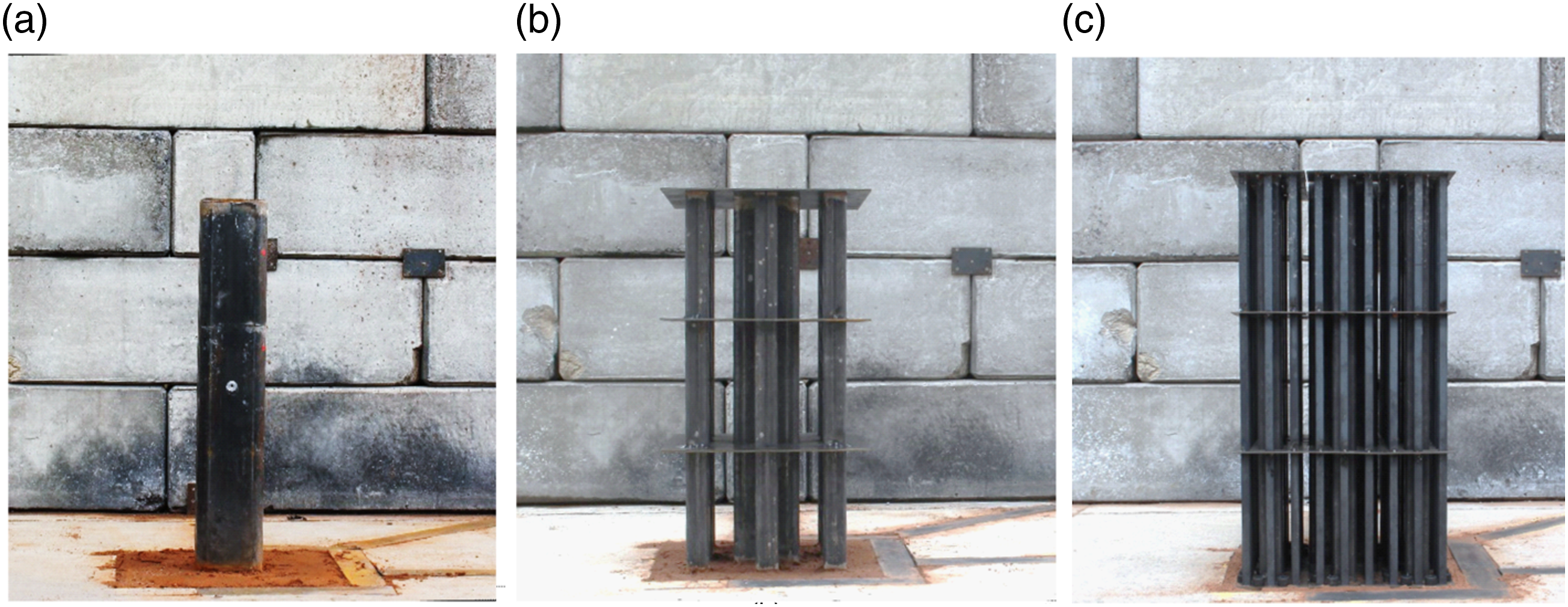
Pressure gauge locations
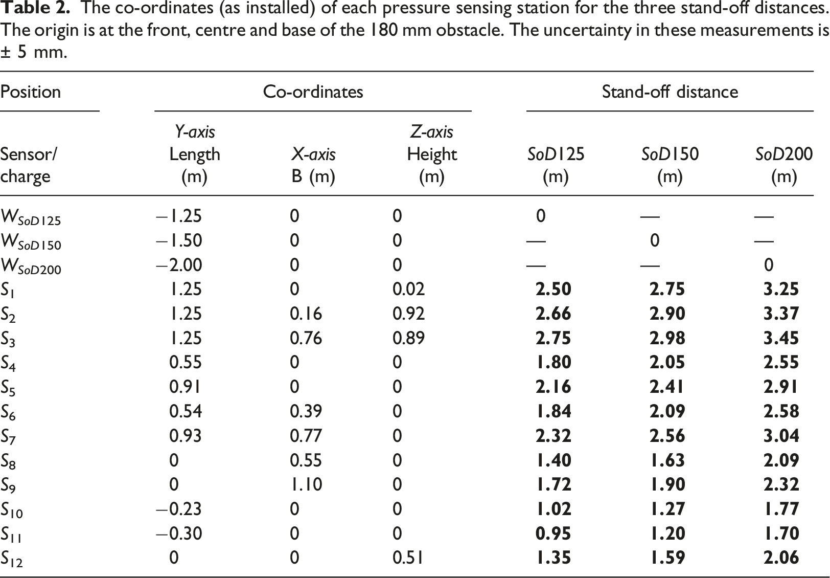
Piezo-resistive Kulite dynamic pressure sensors were used to measure the overpressure at locations carefully selected to capture different aspects of the physics of the blast interaction. A custom made signal conditioner unit was used and a TiePie oscilloscope was used to record the data at 312.5 kHz. Four sensors were employed to measure reflected pressure, of which three sensors (S1, S2 and S3) were fastened onto a 100 × 100 × 10 mm square plate (on the wall in Figure 2) and positioned at chosen locations on the block work wall behind the obstacle. Another sensor was secured in a short metal bush that was then mounted flush on the front face of the 180 mm section (S12, cf. Figure 2(a)) to measure the clearing pressure. The rest were incident pressure gauges, mounted onto steel U-channels that were placed into cut-outs on the concrete pad. The space inside the U-channel was filled with sand and then levelled off to ensure that the metal surface was flush with the ground surface (Figure 2). The following are the locations of the incident sensors: • S4, S5: These sensors were located behind the obstacle and along the 90° ray. They were placed at approximately 2D and 4D from the rear face of the central obstacle (where D refers to the depth of the main obstacle, i.e. 180 mm). • S6, S7: These were placed along a 45° ray behind the obstacle. They were placed at approximately 3D and 6D from the rear corner of the central obstacle. • S8, S9: These were along the line passing through the front edge of the 180 mm section and parallel to the 0° ray line. They have been placed at approximately 3D and 6D from the side face of the central obstacle. • S10, S11: These were placed ahead of the obstacle and along the −90° ray. They were spaced ∼75 mm apart, primarily to measure incoming shock speed.
The co-ordinates (as installed) of each pressure sensing station for the three stand-off distances. The origin is at the front, centre and base of the 180 mm obstacle. The uncertainty in these measurements is ± 5 mm.
Data analysis
All 445 pressure sensor traces (3 SODs × 4 iterations × 12 3 sensors × 3 repetitions, and two additional repeats) had to be pre-processed before they could be automatically extracted using MatLab. For most runs, the data from the sensors were acquired and saved faithfully. However, for a few cases where the recording had spurious data, it had to be manually identified and excluded from further analysis.
To retain as much as possible the essential nature and frequency content of the signals, a wavelet filter was used to clean the pressure traces instead of a low-pass filter. The de-noising of the signal was done using MatLab’s 5th order mlptdenoise as it can accommodate non-uniformly sampled signals (i.e. those traces which had content manually removed). Certain spurious spikes introduced in the resulting de-noised signal were then removed using a 5-point median filter. Subsequently, to clean the pre-shock portion of the signal, instead of using a single value to arrive at the reference level of the signal, an average value of 100 points ahead of the first pressure jump was used. This value was then subtracted from the original signal.
Methods for extracting blast parameters from experimental pressure signals.
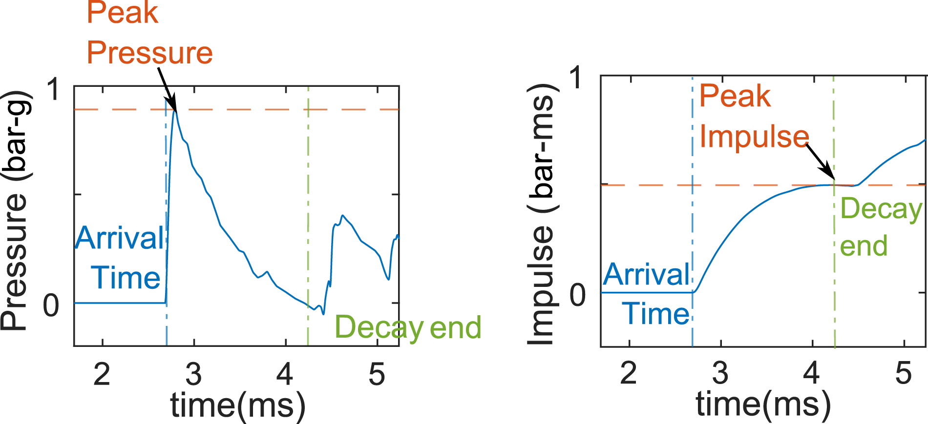
An illustration showing how the peak overpressure, impulse value and decay time were obtained in this study.
Using these methods, the peak pressure, impulse and arrival time were extracted at each station for each experiment. The sensor data have been collated into a single spreadsheet and are provided as supplementary material to this article.
Experimental results
Comparison of pFI-0 against ConWep
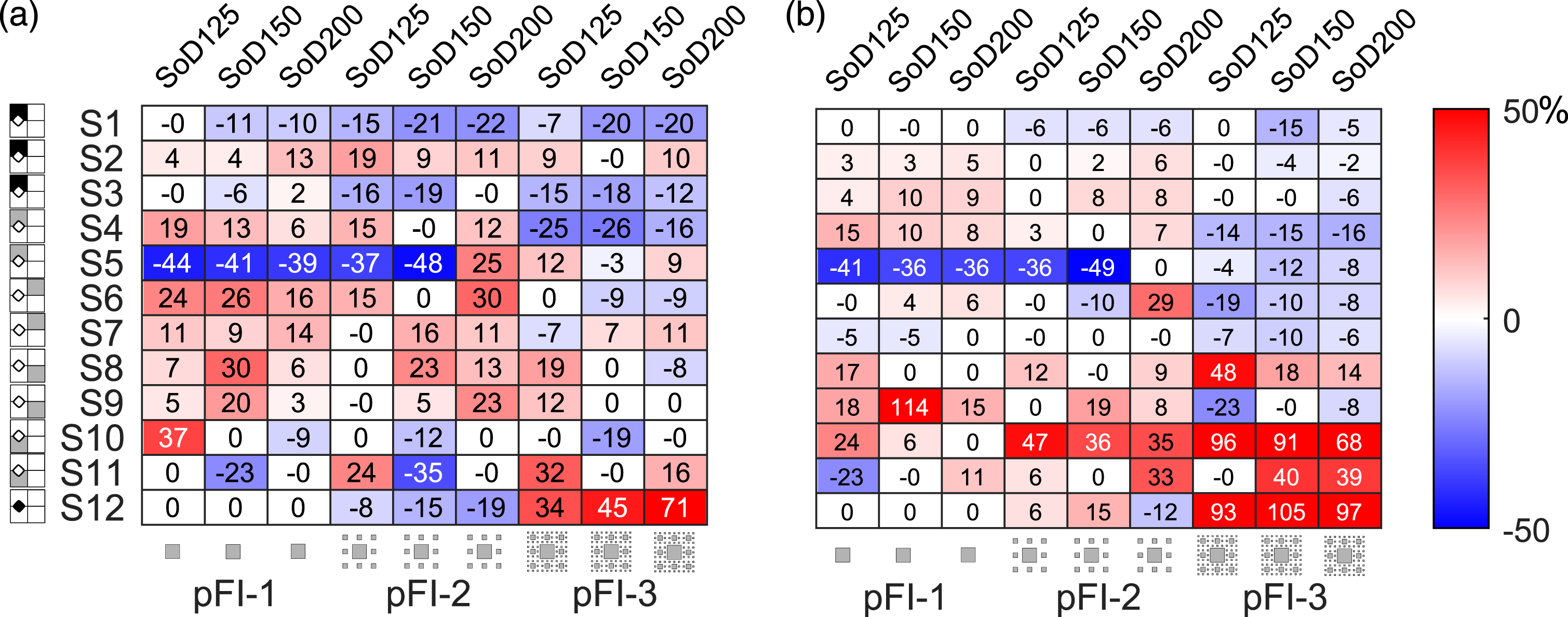
Before evaluating the performance of each obstacle, a data validation exercise was first undertaken to compare the present experimental data for the no-obstacle case (pFI-0) against ConWep (Hyde, 1991) semi-empirical predictions. A TNT equivalence of 1.20 was assumed for PE4, after Rigby and Sielicki (2014). Ratios of measured (average of the three repeat tests) to predicted data are plotted in Figure 4(a)–(c) as heatmaps for arrival time, peak overpressure and peak specific impulse. Here, data from each particular sensor location occupies a given row, with the reflected gauges (S1–S3) and then incident gauges sorted in decreasing distance from the explosive (i.e. S7 is furthest from the charge, S11 is closest). Comparison of pFI-0 data against ConWep for (a) time of arrival, (b) peak overpressure and (c) peak specific impulse. Gauges grouped by reflected (S1–S3) and incident conditions, and sorted in order of decreasing stand-off distance.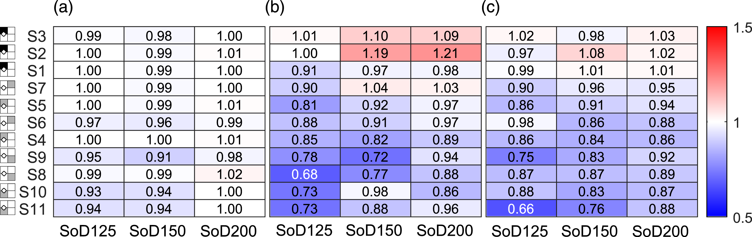
As a guide to the reader, in all the heatmaps presented in this article, the location of a given sensor has been provided against each row using a simplified marker along the left-hand side of the heatmap. The approximate location of the sensor with reference to the obstacle, and the type of the pressure being reported – incident (grey) or reflected (dark) – have been indicated in those markers.
Generally, the arrival time data is in excellent agreement with ConWep, with a maximum deviation of 9%. The agreement is particularly good for the furthest gauges (S4 and further for the SoD125, and SoD150 tests and all gauges for the SoD200 tests), where the deviation does not exceed 6% and is typically within 2%. Consistency of time-of-arrival measurements is discussed in detail in Rigby (2021).
Normally reflected pressure and specific impulse (S1) is also in good agreement with ConWep (9% deviation in peak pressure, 1% deviation in peak specific impulse); however, the oblique gauges (S2 and S3) differ from ConWep somewhat, likely due to angle of incidence/Mach stem effects (Rigby et al., 2015) which have not been accounted for in the ConWep predictions.
At all incident gauges, the deviation of the measured peak pressure values from ConWep is inversely proportional to the stand-off distance to each gauge, ranging from 3% deviation at the furthest distance (S7 for the SoD200 tests; 3.04 m, Z = 4.54 m/kg1/3) to a maximum of 32% for S8 in the SoD125 tests (1.40 m, Z = 2.09 m/kg1/3). This trend is also borne out in the specific impulse data, with a clearer trend of ConWep underpredictions as SoD decreases, up to a maximum of 34%. This is in general agreement with the observations of Bogosian et al. (2002) and believed to be a limitation of ConWep incident predictions. Therefore, in this article, results from pFI-0 are used as more reliable free-field benchmark data.
Pressure and impulse behind the obstacle
In the following sections, example pressure and specific impulse histories are presented at S1, S4, S7, S12 and S10 for each test series (stand-off and iteration number). These are used to make comments on the properties of the attenuated blast wave in various regions surrounding the obstacle, namely, on the target wall; directly behind the obstacle; behind the obstacle on a 45° ray; on the obstacle, and; in front of the obstacle. In the following plots, the inset provides a diagrammatic representation of the gauge location (for further details, refer to Figure 5). A photograph of the sensor arrangement at site (L) and a schematic diagram (R) of the arrangement. The incident shock pressure sensors are placed along rays that are at 0°, 45°, 90° and –90° from the centre of the 180 mm obstacle. The sensor distances may be found in Table 2. NB.: S8 and S9 are located slightly off the 0° ray, on a line passing through the front edge of the 180 mm obstacle.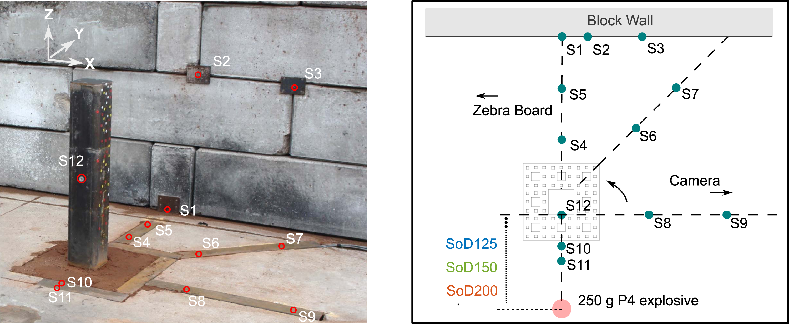
Following this, blast parameters (peak pressure, peak specific impulse and arrival time) are compiled and compared against the free-field (pFI-0) results in order to make general observations. Full pressure histories from all 38 tests are available as supplementary material in this article.
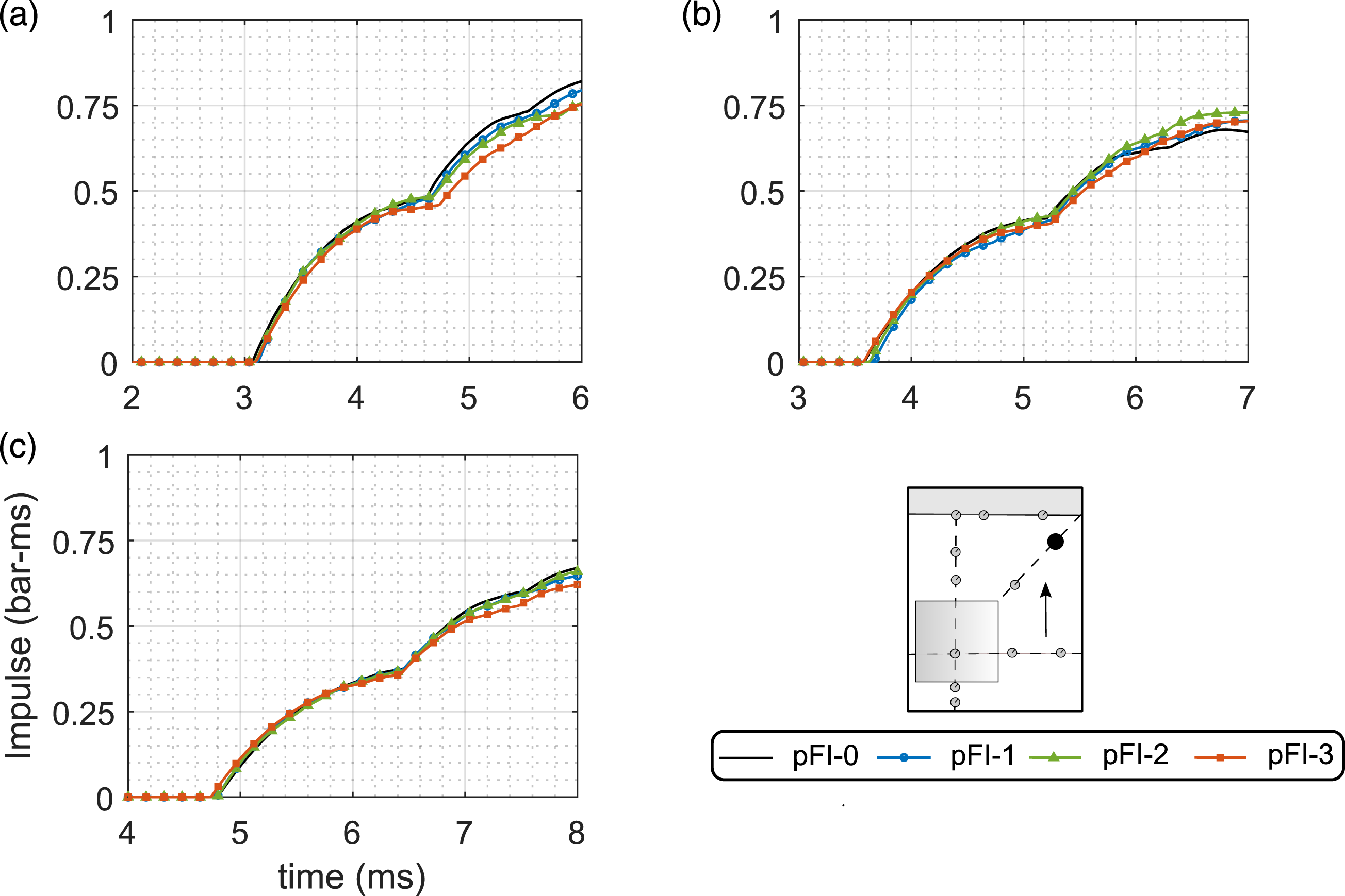
On the target wall
Figures 6 and 7 show, respectively, pressure and specific impulse histories at S1 for the 1.25 m, 1.50 m and 2.00 m tests. This is indicative of the loading imparted to a structure which the pre-fractal obstacle aims to protect. The target wall is located 1.25 m behind the front face of the central obstacle. Pressure histories at S1 for: (a) SoD125, (b) SoD150 and (c) SoD200. Specific impulse histories at S1 for: (a) SoD125, (b) SoD150 and (c) SoD200.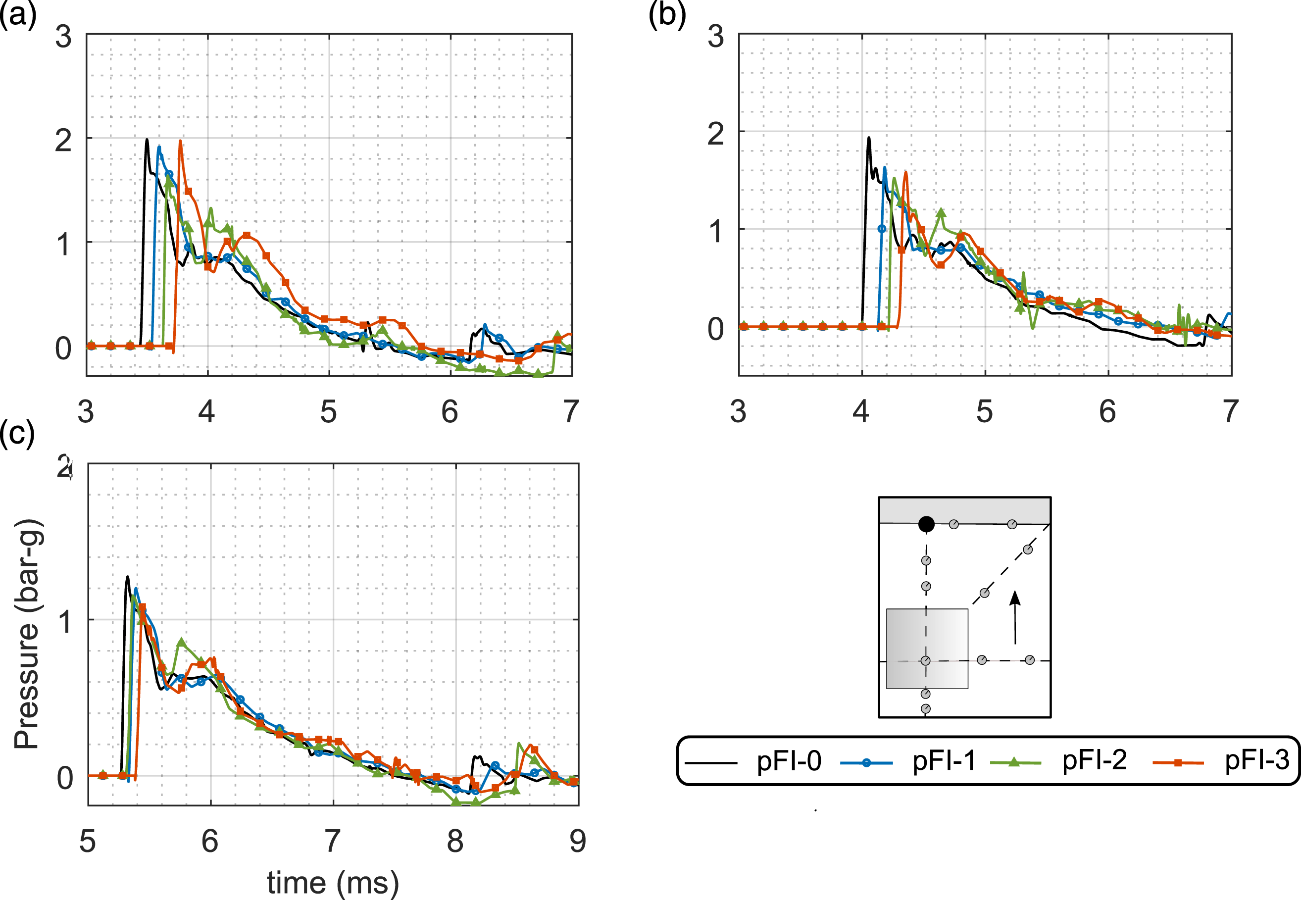
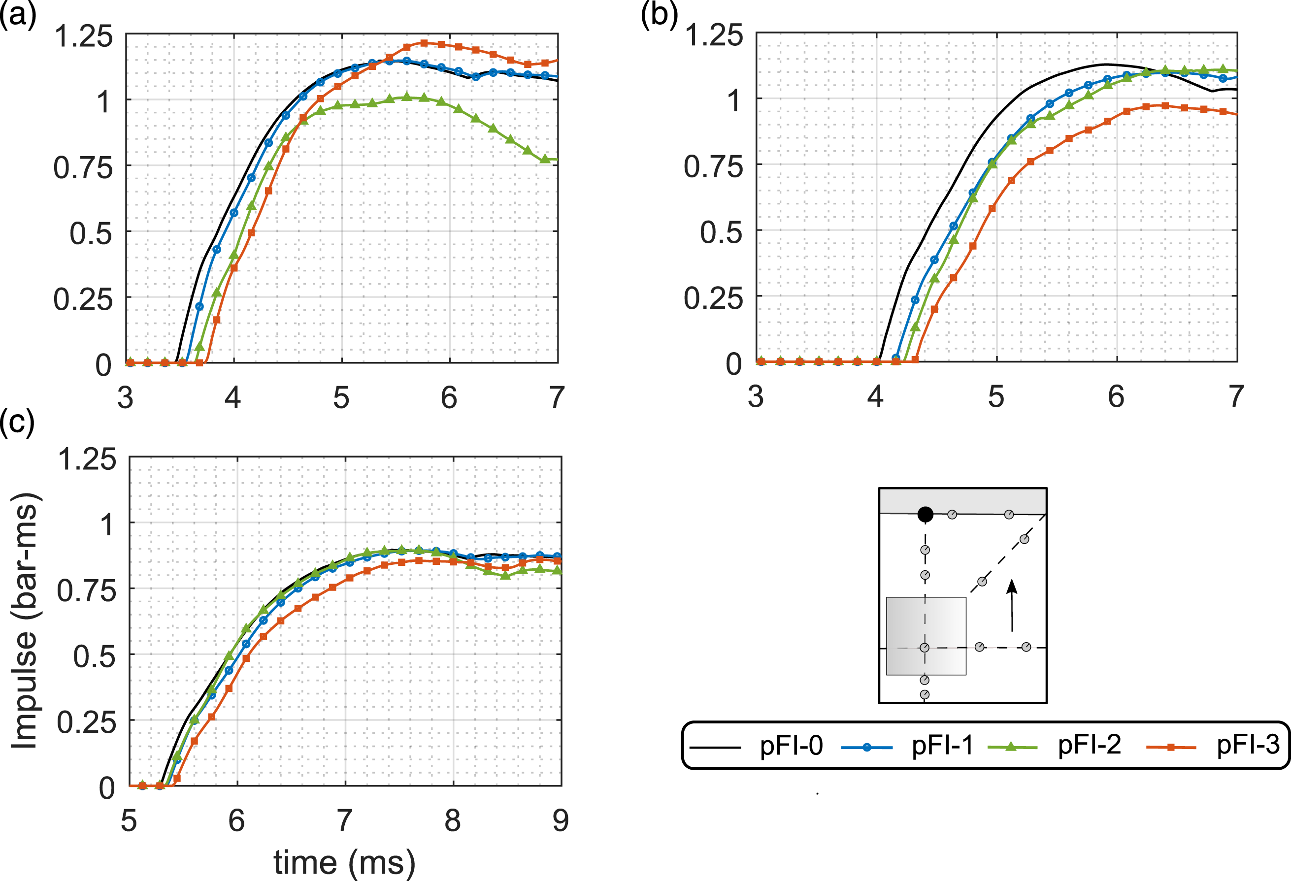
Peak reflected pressures exhibit a noticeable attenuation, which generally increases with iteration number and is relatively consistent with SoD. The maximum peak reflected pressure attenuation is approximately 20% relative to the pFI-0 case, that is, full reflected pressure with no prior blast-obstacle interaction (refer to row 3 of Figure 4). The pressure histories become noticeably more complex with increasing iteration number; the pFI-0 traces resemble the well-known ‘Friedlander’ exponential decay, whereas the pFI-3 traces exhibit multiple smaller peaks and inflection points, indicative of a more complex regime of blast-obstacle interaction, as expected.
There is a marked delay in time of arrival as a function of iteration number, which again is evidence of a more complex attenuation mechanism as the obstacle becomes more fractal-like. This behaviour is largely borne out in the specific impulse histories also, albeit less clearly; the pFI-3 specific impulse is smallest for the SoD150 test but, surprisingly, largest for the SoD125 test. It is clear that the loading on the target wall is made significantly more complex with the introduction of increasingly complex obstacles in the path of the blast wave.
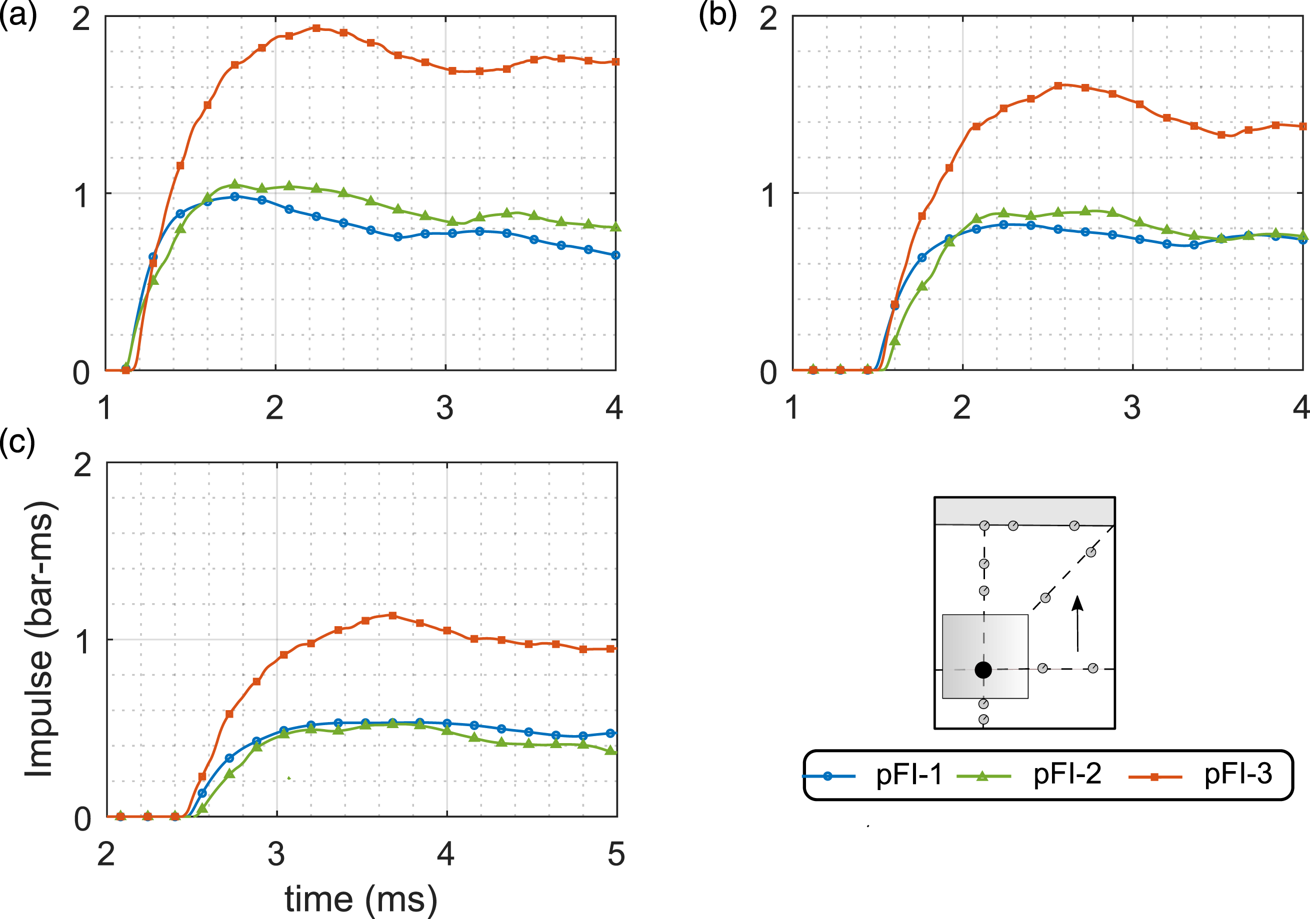
Directly behind the obstacle
Figures 8 and 9 show, respectively, pressure and specific impulse histories at S4 for the 1.25 m, 1.50 m and 2.00 m tests. This is in the immediate shadow region of the obstacles. Pressure histories at S4 for: (a) SoD125, (b) SoD150 and (c) SoD200. Specific impulse histories at S4 for: (a) SoD125, (b) SoD150 and (c) SoD200.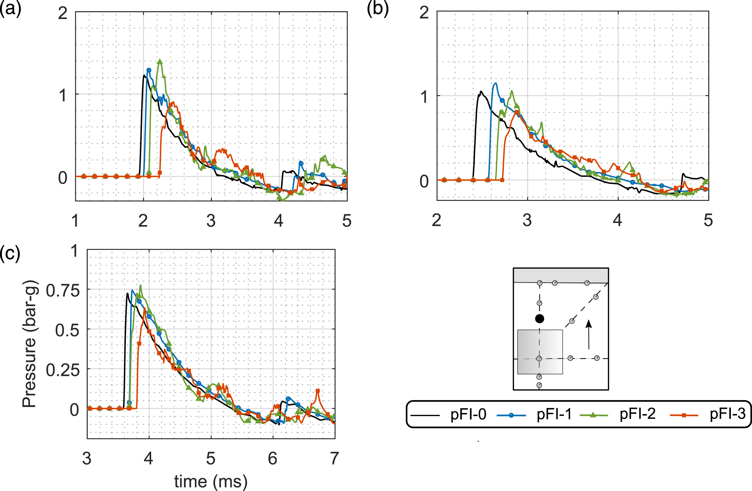
Given the pressure and specific impulse histories on the target wall (S1), a similar level of attenuation was expected immediately behind the obstacle. This is clearly not the case, as an amplification in peak pressure is seen for pFI-1 and pFI-2, for all SoDs, with pFI-3 demonstrating a significant decrease in peak pressure; a reduction of approximately 25% relative to the pFI-0 case. Although the frontal dimensions of pFI-2 and pFI-3 are similar (420 mm and 500 mm, respectively), pFI-3 clearly has a very different attenuation mechanism in the immediate surroundings. There is also a noticeable rounding of the shock front for the pFI-3 cases.
It is likely that the enhancement seen in the pFI-1 and pFI-2 cases is due to the blast wave coalescing and reforming after having been temporarily separated by the obstacle. Despite this localised increase in pressure, the fact that a pressure reduction is observed at the target wall for pFI-1 and pFI-2 (see S1 results above) suggests that this behaviour does not persist. Conversely, pFI-3 causes much more substantial breakup of the blast wavefront (hence the delayed arrival times at both S1 and S4), which therefore takes longer to reform and produces a more pronounced attenuation immediately behind the obstacle.
This is qualitatively supported with evidence from high speed video, as in Figure 10. Here, the incident shock front (above the obstacle), and the components of the shock front that are both reflected by, and transmitted through, the obstacle are visible as disturbances on the zebraboard in the background. For ease of interpretation, approximate shock front locations have been traced and colour-coded in the accompanying images. Note that brightness and contrast values have been slightly increased for presentational purposes. Finally, small markers have been used in the traced plots to mark the foremost and hindmost reflected and transmitted shock fronts at mid-height of the obstacle. A larger number of reflected and transmitted shock fronts are visible for the pFI-3 case relative to the pFI-1 case, which therefore supports the arguments outlined above. Approximate shock front locations determined from high speed video stills for pFI-1 and pFI-3. SoD200 tests at 3 ms and 4 ms after detonation: incident (blue); reflected (red) and; transmitted (green).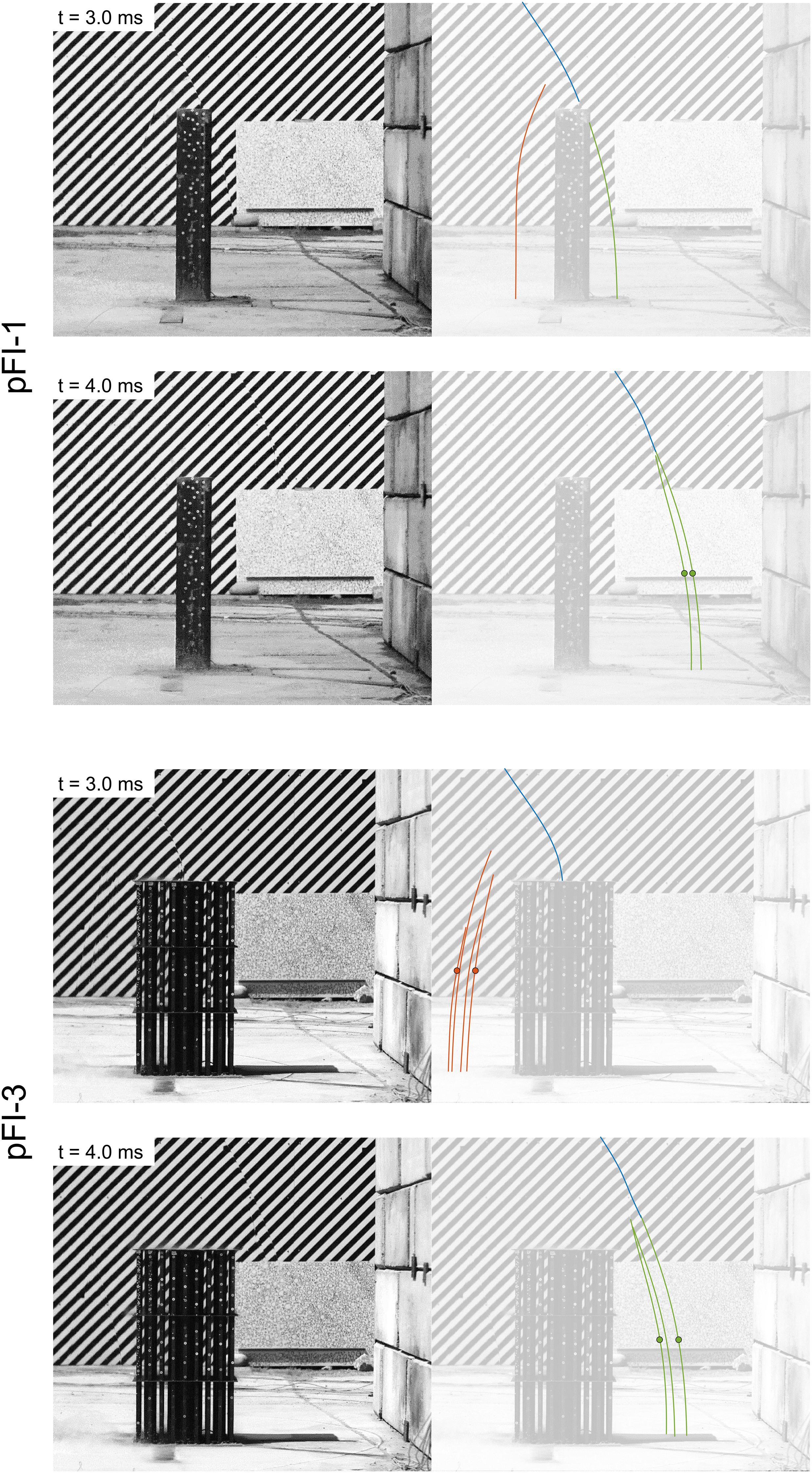
Referring back to Figures 8 and 9, there is a marked delay in time of arrival with increasing iteration number. Peak specific impulses for pFI-0–2 are generally similar, with pFI-3 exhibiting a consistently lower specific impulse.
Behind the obstacle on a 45° ray
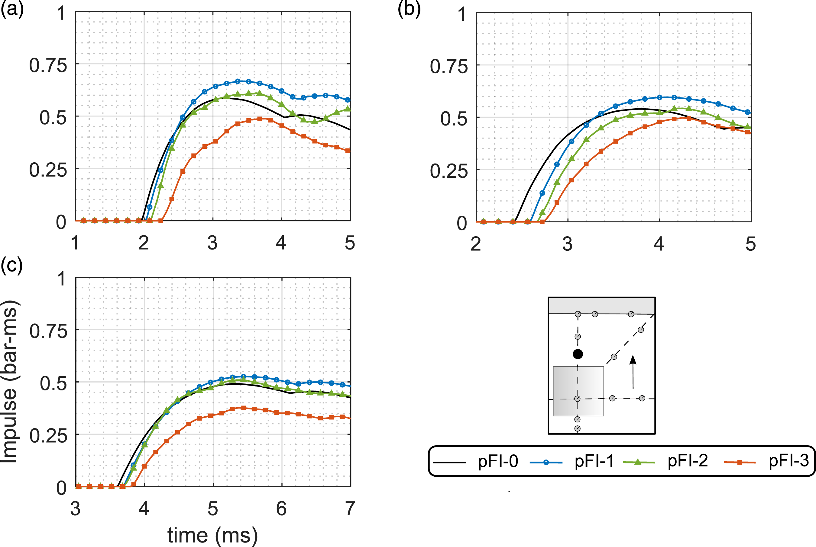
Figures 11 and 12 show, respectively, pressure and specific impulse histories at S7 for the 1.25 m, 1.50 m and 2.00 m tests. This gauge is located along a 45° ray from the obstacle and can be used to make comments on the extent of the disturbed pressure regions. Pressure histories at S7 for: (a) SoD125, (b) SoD150 and (c) SoD200. Specific impulse histories at S7: (a) SoD125, (b) SoD150 and (c) SoD200.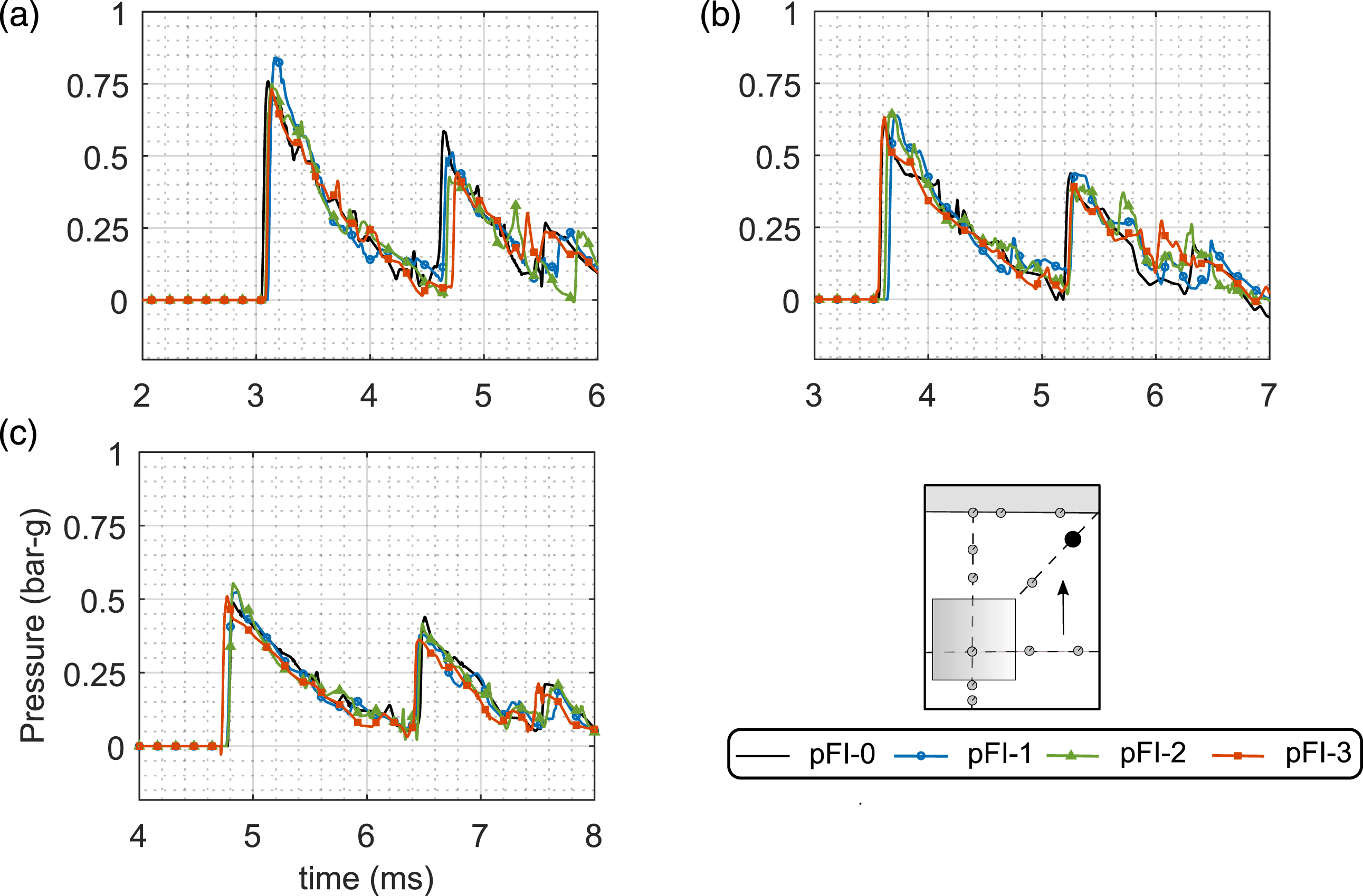
There appear to be no clear differences in the magnitude and form of loading as iteration number increases. These gauges can be said to be positioned outside of the zone of influence (Christiansen and Bogosian, 2012) of the pre-fractal obstacle (0.77 m laterally and 0.93 m behind the front-centre of the 180 mm obstacle, see Table 2) since they do not differ substantially from the free-field loading. A large additional shock can be seen to arrive at the end of the positive phase, which is the reflection of the primary wave off the target wall. For the purpose of compiling and comparing blast parameters later, peak specific impulse values have been taken immediately prior to arrival of this reflected wave.
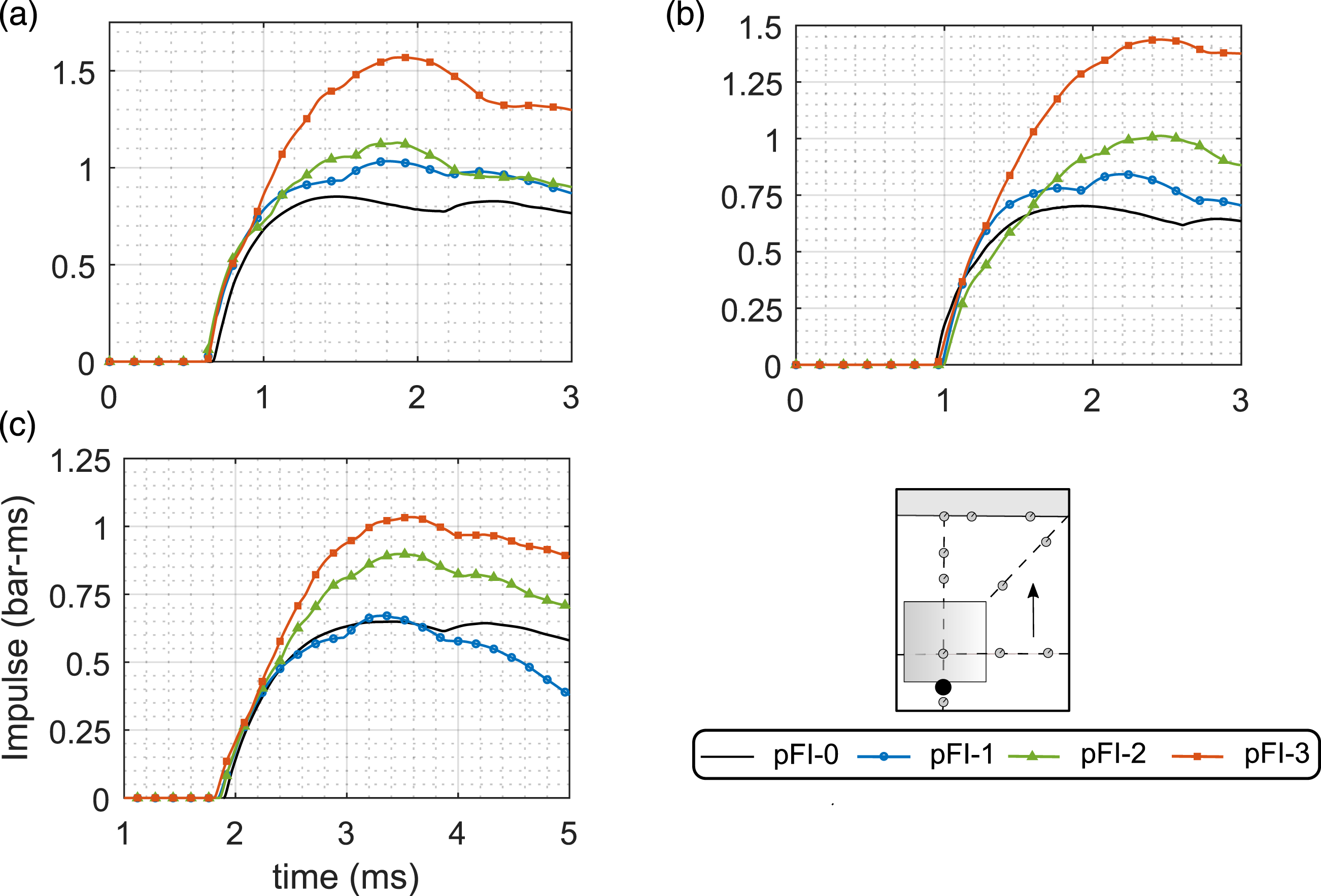
On the central obstacle
Figures 13 and 14 show, respectively, pressure and specific impulse histories at S12 for the 1.25 m, 1.50 m and 2.00 m tests. This is the pressure measured at the centre of the front face of the 180 mm obstacle and therefore there is no free-field equivalent available. Pressure histories at S12: (a) SoD125, (b) SoD150 and (c) SoD200. Specific impulse histories at S12: (a) SoD125, (b) SoD150 and (c) SoD200.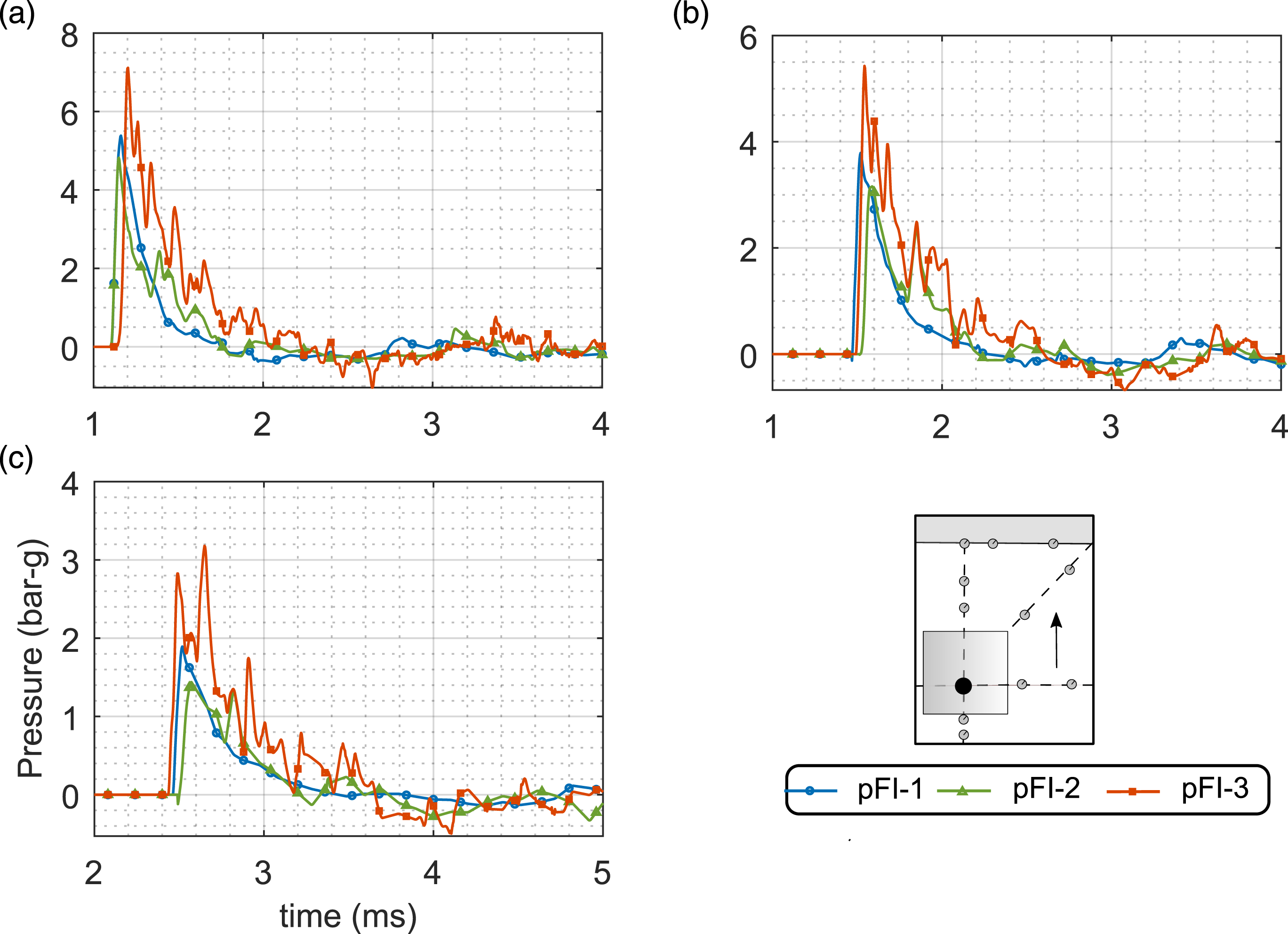
The pFI-2 peak pressure appears slightly lower than in the pFI-1 case, likely due to the small amount of shielding offered by the central 60 mm pole which is located directly in front of the pressure gauge. Whilst there is some later-time deviation between these two signals (with the pFI-2 trace generally increasing above the pFI-1 trace approximately mid-way through the positive phase), the decay times and peak specific impulses are comparable, and there are no noticeable differences in this behaviour with changing SoD.
Conversely, the pFI-3 traces are considerably different, exhibiting a much larger peak pressure and more complex loading history comprising multiple peaks and a substantially greater peak specific impulse. Noticeably, the peak pressure is increased above the pFI-2 value, despite the direct shielding of an additional two 20 mm obstacles. This suggests that a ‘trapping’ mechanism 4 initiates on the third iteration of the pre-fractal, due to the greatly enhanced area:volume ratio and substantially greater number of reflecting surfaces, and is dominant over the shielding effect. It is hypothesised that this trapping mechanism is what ultimately results in attenuation downstream of the obstacle: momentum of the pressure wave in the forward direction is reduced as the shock front is forced to take an elongated path through the obstacle, with a greater proportion of the shock front being redirected perpendicularly or towards the source of the explosion itself.
Peak values of overpressure and peak specific impulse at S12 are compared against ConWep fully reflected values in Figure 15. Peak reflected pressures at pFI-1 are consistently 40–50% lower than ConWep. This suggests that by the time the blast wave reaches mid-height of the 180 mm wide central obstacle, clearing has acted such that the full reflected pressure no longer develops on the loaded surface (Rose et al., 2004). Clearing can also be seen to significantly reduce the pFI-1 peak specific impulse values, to around 40% of the ConWep fully reflected values. This is in agreement with the observations of Ballantyne et al. (2010). Ratios of experimental pressure and impulse values at S12 compared against ConWep fully reflected values.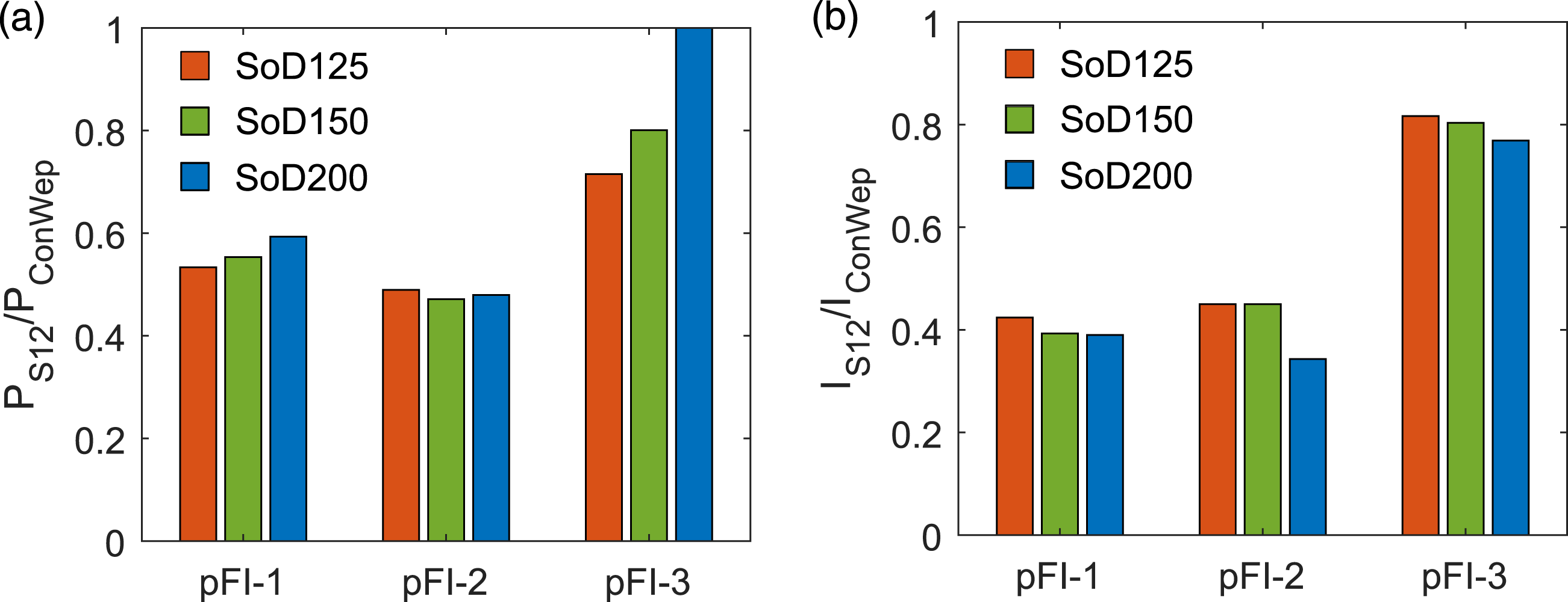
In front of the obstacle
Figures 16 and 17 show, respectively, pressure and specific impulse histories at S10 for the 1.25 m, 1.50 m and 2.00 m tests. This is the pressure measured at ground level directly in front of the central obstacle(s); 0.23 m in front of the 180 mm section, 0.11 m in front of the 60 mm pole and 0.07 m in front of the 20 mm rod for iterations 1–3, respectively. Pressure histories at S10: (a) SoD125, (b) SoD150 and (c) SoD200. Specific impulse histories at S10: (a) SoD125, (b) SoD150 and (c) SoD200.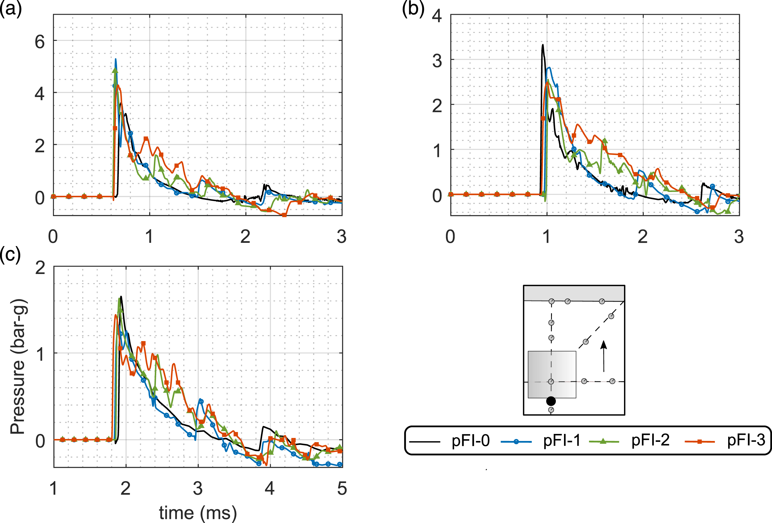
The pFI-1 results are highly similar to the free-field values up until arrival of the reflected wave from the central 180 mm obstacle. This occurs at approximately 1.5 ms, 1.9 ms and 3.0 ms after detonation for the SoD125, SoD150 and SoD200 tests, respectively. Likewise, the pFI-2 results are similar to the free-field values until the arrival of a reflected wave from the 60 mm obstacle, at approximately 1.0 ms, 1.5 ms and 2.4 ms. This is comparatively smaller in magnitude and less well-defined than for the pFI-1 cases due to the much smaller frontal area of the 60 mm obstacle. There is a noticeable rise in pressure in each of the traces due to reflection off the 180 mm obstacles, albeit slightly delayed relative to pFI-1, indicating a slightly elongated travel path or a reduced wave speed. These rises are also observable in the specific impulse histories.
For the pFI-3 cases, the reflected waves are not distinguishable on an individual basis. Instead, they appear to have the combined effect of increasing the pressure value above the free-field case, which persists for the entire positive phase duration. Referring back to Figure 10, this is due to the complex nature of the reflected wave, which does not form a single, coherent wavefront as in the pFI-1 case. Peak specific impulse values increase with increasing iteration number.
The results suggest that the iteration 3 pre-fractal behaves more like a collective obstruction, and supports the stipulation previously that a new type of behaviour is observed as the obstacle becomes more fractal-like.
Discussion
Compiled results
Arrival time, peak pressure and peak specific impulse have been compiled at each gauge location, for each pre-fractal iteration and stand-off distance. The mean values from each triplicate series tests are presented in Figure 18 for arrival time and Figure 19 for peak pressure and peak specific impulse. Here, results are presented as a percentage increase above the pFI-0 (free-field) values, with the exception of the S12 results which are compared against the pFI-1 values due to there being no free-field equivalent. Using Welch’s t-test, the statistically insignificant (at 80% confidence) differences have been masked out with zeroes.
5
Here the gauges have been simply listed in numerical order. Percentage change in arrival time at each sensor location, compared against pFI-0 case (for S12, the comparison is against pFI-0.) Only statistically significant values are reported. Percentage change in (a) pressure and (b) impulse at each sensor location, compared against iteration 0 case (for S12, the comparison is against pFI-0). Only statistically significant values are reported.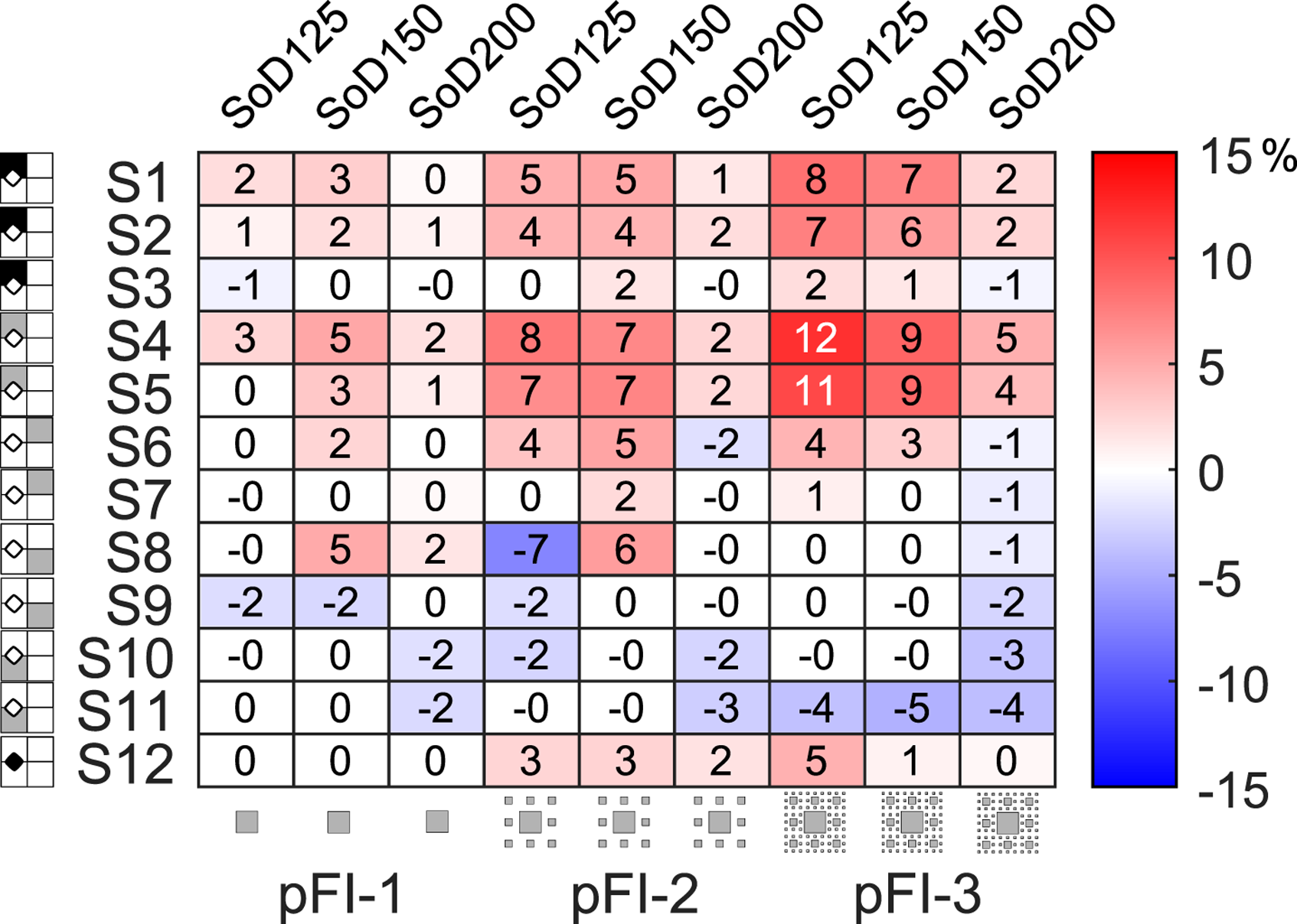
A number of general observations can be drawn: • There is a clear trend of increasing arrival time behind the obstacle (S1–S5) with increasing iteration number. This effect is seen to decrease as the vertical/lateral distance along the target wall increases (S3 arrival times most closely resemble those from pFI-0 throughout). • Arrival times at S7 appear unaffected, suggesting the zone of influence does not extend beyond this point on the 45° ray. • Pressure and specific impulse values do not follow such a simple trend, suggesting that a delayed arrival time is not a direct indicator of a weakened shock wave (Zhou and Hao, 2008). • Generally, peak pressure values can be seen to decrease downstream of the obstacle (S1–S5). • Whilst pFI-1 exhibits a consistent increase in peak specific impulse behind the obstacle (attributed to wave coalescence), pFI-3 exhibits a consistent decrease in peak specific impulse behind the obstacle. This suggests that the mitigation properties of the obstacle improve as it approaches a true fractal. • Mitigation for pFI-1 and pFI-2 is generally restricted to immediately behind the obstacle (S4), attributed to shadowing. For pFI-3, mitigation is observed over a much greater area, again signifying enhanced mitigation properties as the obstacle becomes more fractal-like. • Peak pressure and peak specific impulse values are consistently higher at S12, due to the aforementioned ‘trapping’ mechanism. It is hypothesised that this is what ultimately leads to the observed downstream mitigation. • Maximum values of attenuation of 26% for peak pressure and 19% for peak specific impulse were observed for pFI-3.
Frequency analysis of the pressure signals
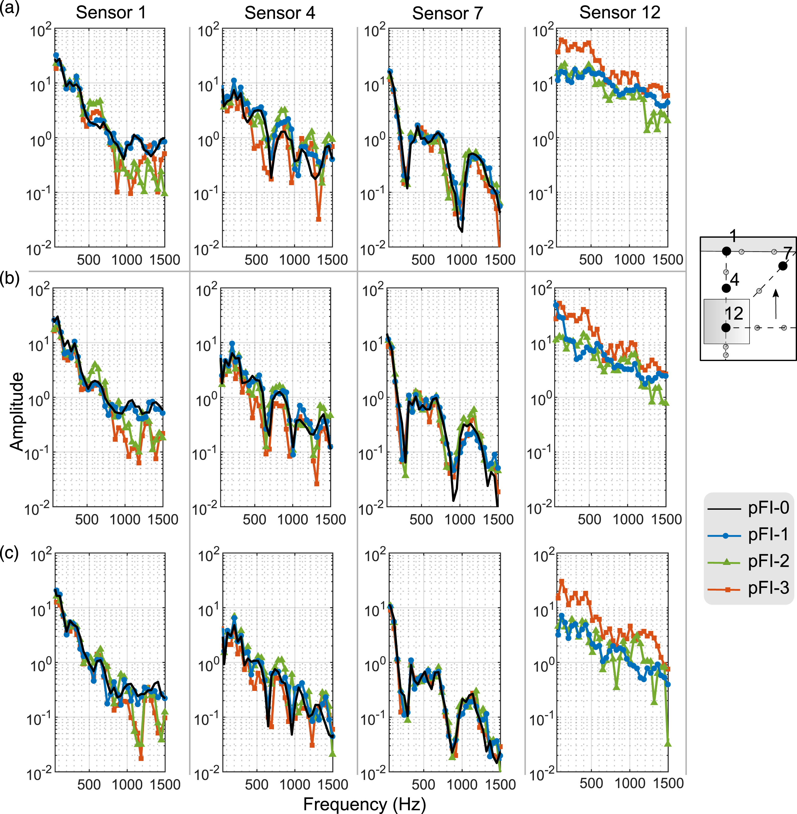
Due to the highly complex pressure and impulse histories at various locations surrounding the obstacle, it is apparent that only considering peak pressure, specific impulse and time of arrival is not sufficient to fully characterise the obstacle’s influence. Therefore, a frequency domain analysis was carried out at select sensor locations, namely, S1, S4, S7 and S12, as shown in Figure 20. The amplitudes of the frequency spectrum were averaged for the triplicate tests at each SoD, for each pre-fractal arrangement. The following observations can be made: • There is a small increase in mid-range frequency components (500–700 Hz) at S1, although this appears to diminish with increasing SoD. • The spectra at S1 exhibit a noticeable reduction for pFI-2 and pFI-3 at higher frequencies ( • Mid to high frequencies ( • Lower to mid-range frequencies (300–500 Hz) are reduced for pFI-3 at S4, particularly at shorter stand-off distances. This may explain the apparent rounding of the shock front seen in the pressure traces. • There are a number of troughs at specific frequencies at S4. There is a prominent trough at 1200–1300 Hz which is absent in the pFI-0 case (i.e. that frequency component is present in the free-field case), but is particularly significant in the pFI-3 spectra, for all SoDs. This is likely due to the trapping mechanism observed previously. • There are no noticeable differences in the S7 spectra, confirming that this gauge lies outside of the zone of influence of the pre-fractal obstacles. • There are considerable increases in the frequency spectra at S12 (on the front face of the central obstacle) when comparing pFI-3 to pFI-1, particularly for frequencies <500 Hz. There are intermittent peaks in the pFI-3 spectra between 600–1100 Hz which are absent in the pFI-1 and pFI-2 spectra. This is best shown in the pFI-3, SoD125 spectra, and is again indicative of the trapping mechanism seen in the pressure and specific impulse histories at this sensor. Frequency analysis for different stand-off distances (a) 1.25 m, (b) 1.50 m and (c) 2.00 m.
Towards an engineering approach to predict pressures
It is clear from the results discussed previously that the pre-fractal obstacle becomes more effective at attenuating blast pressures as iteration number increases. This is likely due to the provision of a much greater number of reflecting surfaces, which restricts the flow of the blast wave and also gives rise to trapping. In order to better make use of this knowledge, the following section attempts to develop an engineering model to predict this behaviour. Taking inspiration from shock-tube studies (Berger et al., 2010; Golovastov et al., 2022; Honghui and Yamamura, 2004), a new parameter termed the obstruction ratio, OR, is defined, as shown schematically in Figure 21. An illustration using pFI-2 obstacle to demonstrate the calculation of the obstruction ratio, OR, as defined in equation (1).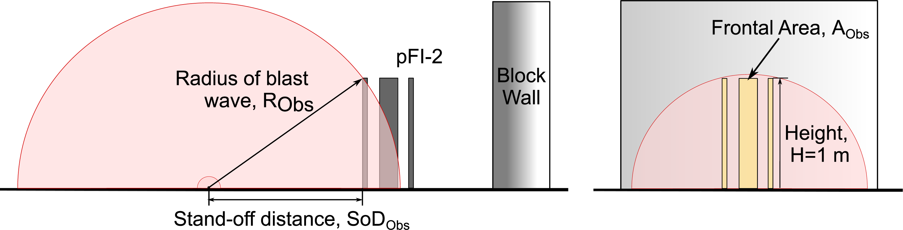
Since the purpose of such a parameter is to quantify the obstruction offered by the obstacle to the transmission of the blast wave, the following was reasoned. For an obstacle of a given size, if the explosion were to be closer, the obstruction offered would be greater; and when farther away, it would be lower. This may be quantified by considering the hemispherical surface area of the wave that will be disrupted by the obstacle. An apt measure of the disruption would be the frontal (projected) area of the obstacle AObs itself. This disruption is seemingly maximal when the blast wave arrives at the top edge of the obstacle (see Figure 21). The radius of the blast wave at that instant RObs can therefore be used to define OR as in equation (1)
Arrival time, peak overpressure and peak specific impulse at S1, S4 and S7 are plotted against OR in Figure 22. Also shown are the coefficients of determination, R2, of a linear relationship fit to the results from each pre-fractal obstacle. There is a clear linear trend in all cases, and with the exception of specific impulse at S1, the R2 values range from 0.87 to 1.00. Arrival time, in particular, demonstrates a strong linearity, with R2 values no lower than 0.96. It is not the intention of this work to derive more sophisticated predictions of blast attenuation, it is necessary only to demonstrate that there is a great degree of predictability of blast parameters when compared to the newly-defined obstruction ratio, as this will form the basis of later work on this subject. Plots of (a) arrival time, (b) overpressure and (c) impulse for sensors S1, S4 and S8 against the obstacle ratio OR, as defined in equation (1). Unlike previous figures, here, the colour represents SoD, and marker shape represents the iteration type.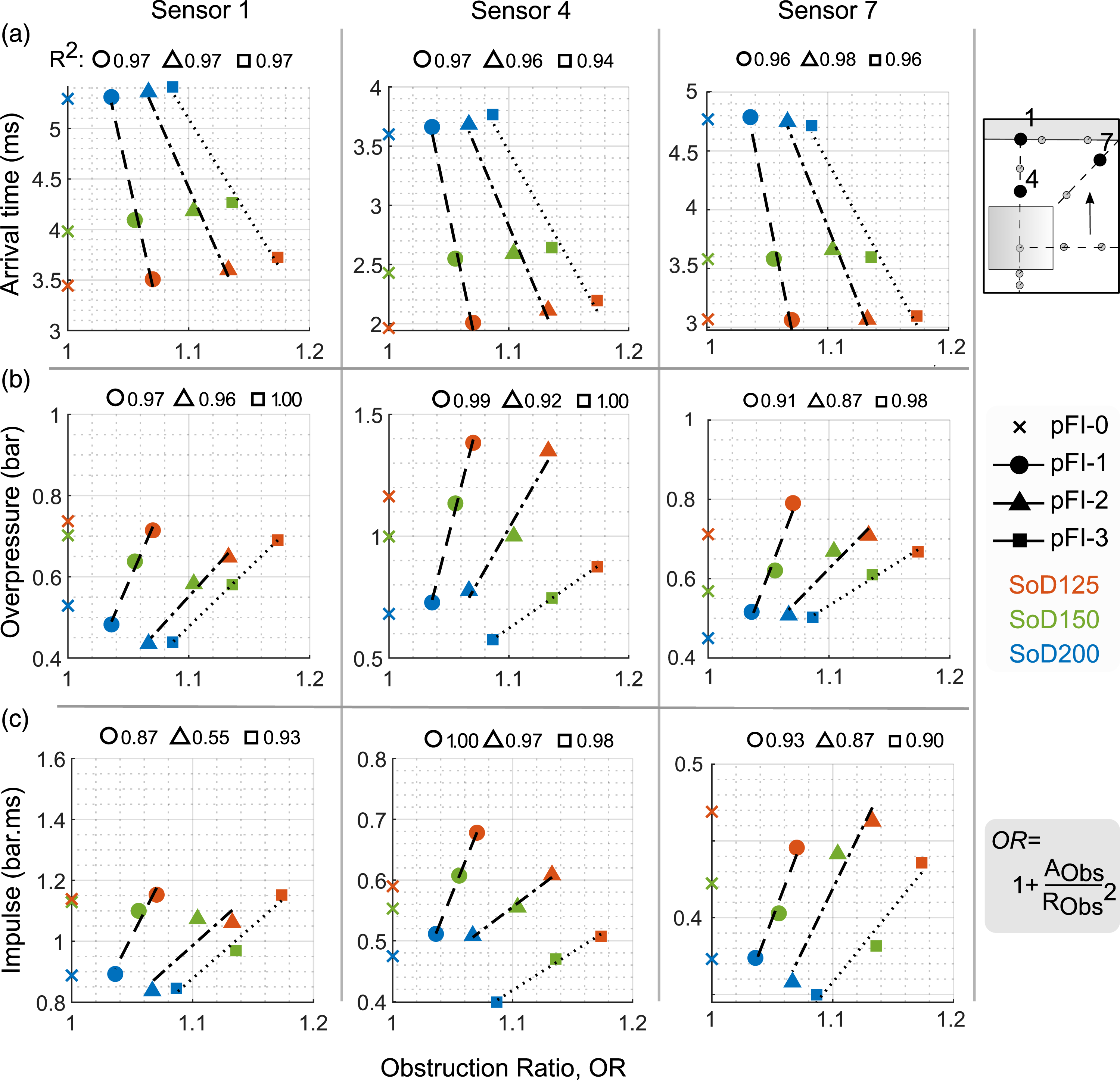
A few comments on the overpressure plots are provided below, but similar conclusions may be drawn when considering the other two parameters. • The overpressure almost always increases at a slower rate for pFI-3 than the two previous iterations. This slope depends on the location of the sensor and OF. • It is assumed that this slope is specific to each obstacle configuration. It may then be surmised that an obstacle of pFI-1 type, that has the same width as pFI-3, would result in higher pressures (and thus lower attenuation), in its vicinity. • This suggests that using an obstacle comprising multiple smaller parts, that is, a pre-fractal, is more effective than a single, larger obstacle. • The extent of validity of this linear relationship, however, needs to be investigated further using CFD or additional experiments.
Outlook
The pFI-3 obstacle results in a more significant and uniform disruption of the blast wave, as opposed to previous iterations whose influence is largely restricted to the shadow region immediately behind the obstacle. This disruption is characterised by a reduction in pressure and impulse at the target wall, accompanied by a delayed arrival time and substantial rounding of the shock front (i.e. reduction in mid- and high-range frequency components immediately behind the obstacle and on the target wall, respectively). There is also a significant increase in pressure and impulse in the vicinity of the obstacle, with evidence of multiple wave reflections termed ‘trapping’. This is only seen for the pFI-3 case, suggesting it is fundamental behaviour observed only as the obstacle becomes more fractal-like.
The pressure reductions on the target wall (S1) are comparable to reductions seen in similar tests using plants and hedges for blast mitigation (Gebbeken et al., 2017; Warnstedt and Gebbeken 2020).
6
These similar attenuation properties are particularly noteworthy when considering the following: • The 20 mm spacing between the obstacles in the current testing is relatively large compared to the spacing between the leaves. • The obstacles remained elastic throughout the current testing, whereas the plants and hedges could sway and even experience loss of biomass. Although it has been suggested that structural strength of the protective structure is secondary when considering its mitigation properties (Rose et al., 1998), this does provide an additional means for energy dissipation. • The relatively smooth surface of the square poles compared against the small length scales and rough surfaces of the plants, with surface roughness having been identified as a significant parameter (Hajek et al., 2016).
Each of these is believed to have enhanced the mitigation properties of the plants and hedges. Since these are not features of the pre-fractal obstacles tested herein, yet similar levels of mitigation were achieved, the results highlight the good intrinsic mitigation properties of pre-fractals and make a strong case for the use of pre-fractal obstacles in urban blast protection settings.
Whilst testing in this article used a single pre-fractal obstacle, a collection of obstacles arranged into a fence-type protective structure will likely result in more significant breakup of the blast wave and greater mitigation over a larger area. Further, the configuration tested in this article was that of a pseudo-2D fractal extruded along its height. It is probable that a fractal that is self-similar in all three dimensions would result in even greater attenuation than observed herein, and should be a subject of further study.
Summary and conclusions
This paper aimed to quantify the attenuation of a blast wave after interacting with a pre-fractal obstacle of increasing complexity (i.e. increasing fractal iteration), and, in turn, better understand blast-obstacle interaction with complex obstacles. Experiments were performed using 0.25 kg hemispherical PE4 charges at three different scaled distances, Z = 1.87, 2.24, & 2.99 m/kg1/3. Three Sierpinski carpet pre-fractal configurations – pFI-1, pFI-2 and pFI-3 – were tested, as well as reference configuration without any obstacle, termed pFI-0, to ascertain equivalent free-field values.
On comparing the performance of the pre-fractal obstacles with the reference case, reductions in peak overpressure up to 26% and peak specific impulse up to 19% were observed. The obstacles were also found to act effectively as low-pass filters, and their disruption of the blast wave was found to be more significant at closer stand-off distances. For the highest iteration number, pFI-3 (i.e. the most fractal-like obstacle), attenuation of the blast wave was spread over a much larger area behind the obstacle, as opposed to being limited to the shadow region immediately behind the obstacle as with previous iterations. This was coupled with a substantial increase in pressure and impulse in the vicinity of the obstacle itself, with a corresponding increase in the frequency spectra, attributed to multiple wave reflections off the smaller obstacles in a process known as ‘trapping’.
The results indicate that the mechanism of blast mitigation of pre-fractal obstacles is fundamentally different from singular or arrays of regular obstacles. Blast parameters at any given location were found to be linearly dependent on the newly-defined obstruction factor, OF, suggesting that this behaviour is inherently determinable. This also provides an important metric for the future design of novel pre-fractal protective structures.
Supplemental Material
sj-xlsx-1-prs-10.1177_20414196221144066 - Supplemental Material - Experimental investigation of blast mitigation of pre-fractal obstacles
Supplemental Material, sj-xlsx-1-prs-10.1177_20414196221144066 for Experimental investigation of blast mitigation of pre-fractal obstacles by Obed Isaac, Omar G Alshammari, Samuel D Clarke and Sam Rigby in International Journal of Protective Structures
Footnotes
Acknowledgements
We would like to thank Paul Blackbourn for helping with the fabrication of the obstacles, and Roy, Andrew, Jack, Ash, Richard, Tommy, Dain and Scott for running and assisting in the experimental campaign. SER would like to thank EJR for his genuine interest in the project from its inception, and for helping to shape a lot of the early concepts.
Declaration of conflicting interests
The author(s) declared no potential conflicts of interest with respect to the research, authorship, and/or publication of this article.
Funding
The author(s) disclosed receipt of the following financial support for the research, authorship, and/or publication of this article: This work was funded by the UK Engineering and Physical Sciences Research Council (EPSRC), project number EP/S037241/1.
Notes
Supplemental Material
Supplemental material for this article is available online.
References
Supplementary Material
Please find the following supplemental material available below.
For Open Access articles published under a Creative Commons License, all supplemental material carries the same license as the article it is associated with.
For non-Open Access articles published, all supplemental material carries a non-exclusive license, and permission requests for re-use of supplemental material or any part of supplemental material shall be sent directly to the copyright owner as specified in the copyright notice associated with the article.