
Abstract
Elastomer coatings have been found to offer protection to structural components when subjected to dynamic load cases, such as impact and blast. One such application of interest is the protection of concrete structures. Elastomer coatings have the potential to provide a cost effective and practical protective solution. The dynamic response of quasi-brittle concrete structures to blast loading is complex, with a range of dynamic response regimes. It remains to be identified in which regimes of response an elastomer coating can offer a protective benefit. Numerical and analytical modelling of thin, one-way reinforced concrete slabs subjected to varying intensities of simulated blast loading is carried out, in order to ascertain the protective effect of an elastomeric coating. Three configurations are considered: uncoated, coated with elastomer on the blast-receiving face and coated with elastomer on the non-blast-receiving face. It is found that the slab is relatively insensitive to the elastomer coating during response regimes where concrete damage is minimal. At higher load intensities, where the slab exhibits severe damage, the numerical results indicate a substantial reduction in slab deflections may be achieved by coating on the non-blast-receiving face. At the highest loading intensities, a shift in failure mechanism is observed to one dominated by transverse shear at the supports. An analytical model quantitatively predicts a substantial coating benefit in protecting against this failure mechanism.
Introduction
The retrofit of ageing, vulnerable infrastructure to protect against the detrimental effects of blast has been at the forefront of global agendas in recent years. One practical, low-cost solution that has gained much attention is the use of a spray-on elastomer coating.
Experimental blast trials on elastomer-coated masonry structures have yielded encouraging results, indicating an impressive ability to contain fragmentation debris and to maintain structural integrity for significantly higher blast intensities compared to un-retrofitted counterparts (Baylot et al., 2005; Knox et al., 2000; Davidson et al., 2004). However, to date, comparatively little work has focused on spray-on elastomers applied to concrete substrates, despite concrete representing a significant proportion of the ageing, vulnerable infrastructure in today’s built environment.
In one exception, Raman et al. (2012) performed a numerical analysis on a polyurea-coated, reinforced concrete (RC) slab, subjected to a peak reflected pressure, p a = 2477 kPa and impulse, I a = 518 Pa s. For a slab depth of 60 mm, reinforced with 5 mm rebar on the tension side, deflection reductions of more than 40% were reported when a 4 mm thick polyurea coating was applied. Little is understood about the mechanism by which the elastomer achieves this effect and thus there is a lack of clarity regarding when and where this retrofit solution is optimally effective.
In this investigation, the aim is to address this question using finite element analysis (FEA), which has been validated against published blast test results (Fallon & McShane, August 2019), to identify the response regimes of a thin, one-way reinforced concrete slab, subjected to simulated blast loading and the influence of elastomer coating. In previous work (Fallon & McShane, August 2019), the details of the numerical model, including the concrete and elastomer material models were developed. It was concluded in (Fallon & McShane, August 2019) that during air blast loading the elastomer does not contribute a significant fluid-structure interaction effect. A fully coupled fluid-structure interaction simulation is therefore unnecessary, with the loading adequately represented by a purely Lagrangian approach, in which a pressure-time history is directly applied to the structure (Fallon & McShane, August 2019). In the current investigation, the response regimes of uncoated concrete sections subjected to a range of simulated blast loads are first identified. Next, the response regimes of two coated configurations are examined: (i) a reinforced concrete section coated on the blast-receiving face and (ii) a reinforced concrete section coated on the non-blast-receiving face. Analytical modelling is then used to further describe these regimes of response, and to understand the key parameters at play. Finally, the findings are summarised on an analytically derived design map, highlighting the regime boundaries and the regimes in which the coating is likely to offer effective protection.
Numerical model development
FEA is carried out using the commercial code ABAQUS/Explicit (ABAQUS, 2011). It is used to interrogate the behaviour of unreinforced and reinforced concrete sections subjected to a range of simulated blast intensities.
A section is modelled, subjected to plane strain boundary conditions on two faces – analogous to a representative element of a slab of infinite width (i.e. the displacement is constrained along the width direction). For the unreinforced case, a 1 m span is modelled as a 3D deformable part illustrated in Figure 1(a). The dimensions of the modelled part are 500 mm × 50 mm × 10 mm and a symmetry boundary condition is applied at the midspan. The concrete is meshed with 3 mm 3D, 8-node linear elements (C3D8 in ABAQUS notation), chosen on the basis of a mesh sensitivity study on the deflection response. The support conditions at the ends of the span are illustrated in Figure 1. A degree of boundary compliance is introduced to avoid unrealistic stress concentrations – a 50 mm length at the end of the span is placed between rigid, frictionless surfaces which terminate with a radius of curvature of 90 mm. The geometries used in the numerical modelling of: (a) an unreinforced concrete section and (b) a reinforced concrete section. The examples show a 5 mm elastomer layer on the blast-receiving face of each section.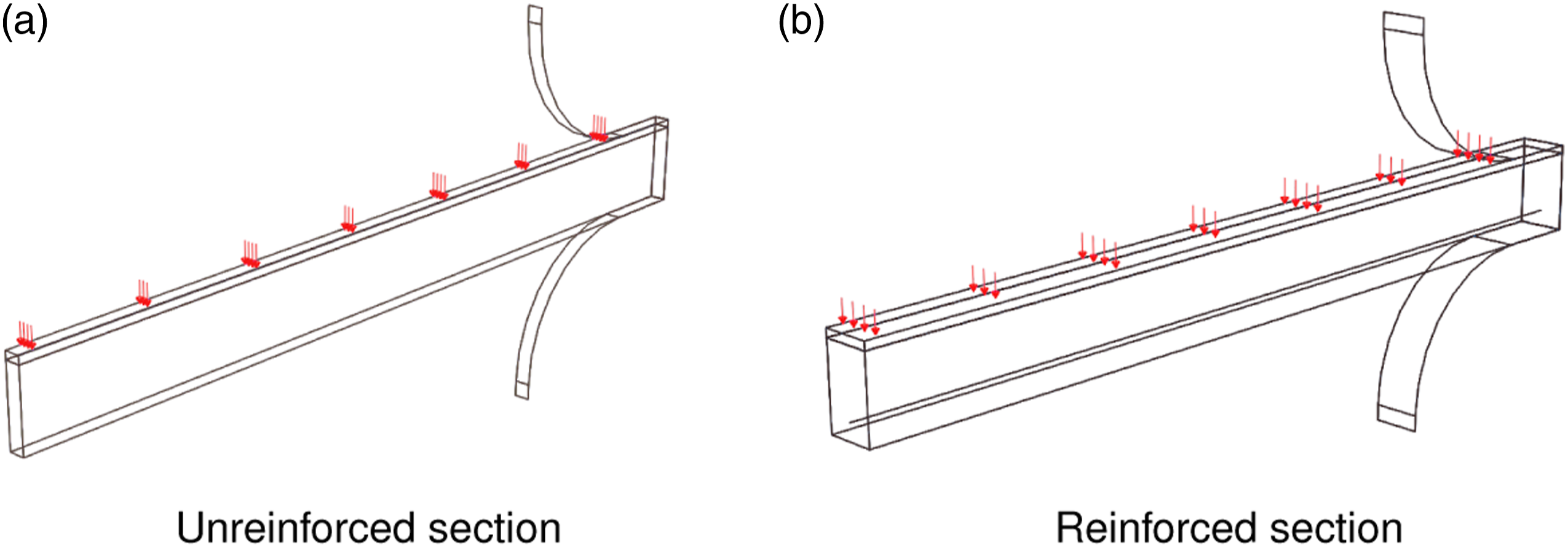
Blast loading is modelled using a pressure-time history and is applied uniformly to the top surface of the section. It is noted that this omits some of the detailed interactions experienced during an explosive detonation near to a structure. However, as shown in (Fallon & McShane, August 2019), this approach provides a good match to a fully coupled Eulerian-Lagrangian simulation for a planar blast wave interaction. The blast wave is approximated by the exponential time-dependence in equation (1), where p
a
is the peak applied blast pressure and t
i
is the decay time (Kambouchev et al., 2006). The impulse, I
a
is thus given by equation (2)


Concrete constitutive model
The concrete material model is chosen as the Concrete Damaged Plasticity (CDP) model, available in ABAQUS/Explicit (ABAQUS, 2011). The model parameters are summarised here with further details provided in (ABAQUS, 2011) and (Fallon & McShane, August 2019). The model considers the concrete as a solid continuum which exhibits isotropic, damaged elasticity and isotropic, pressure-dependent plasticity. The compressive response is defined according to the empirical relationships set out in the CEB-FIP Model Code (CEBFIP CEB-FIP model code 1990: design code, 1993) for a concrete of compressive strength, σ cu = 39.5 MPa. The tensile response is based on the relationship proposed by Hordijk (1991) for a concrete tensile strength, σt0 = 4.2 MPa. Compressive and tensile damage parameters, d c and d t quantify the degradation of elastic stiffness and can take values between zero (undamaged material) and one (fully damaged material). They are defined according to the relationship proposed by Birtel and Mark (2006). An undamaged elastic modulus of 28.3 GPa is assumed, with a Poisson’s ratio, ν = 0.2 and a density of 2550 kg m−3. We opt to omit concrete strain rate dependence given the lack of published data on the full suite of CDP parameters. This constitutive assumption might affect the model fidelity, in terms of reproducing specific experimental results (for which a more detailed representation of the blast loading conditions would also be required), however, within the scope of this investigation, it provides an adequate tool for studying the fundamentals of concrete response regimes and the influence of an elastomer coating. Nonetheless, the model is validated at higher strain rates by comparison with experimental results (Fallon & McShane, August 2019; Fallon & McShane, June 2019). In particular, the predictive quality of this concrete model was demonstrated in (Fallon & McShane, August 2019) by comparison with two sets of published experimental results on the blast testing of uncoated, reinforced concrete slabs (Wang et al., 2013; Wu et al., 2009). In (Fallon & McShane, August 2019), numerical predictions of cracking and spall patterns were qualitatively compared with experimental observations and it is shown that the model is capable of predicting well the characteristic crack patterns for both the blast-receiving and non-blast-receiving faces of the RC slab. Furthermore, reasonable agreement was achieved with measured slab deflections for blast cases that had relatively large stand-off. Thus, we have confidence that the concrete material model is adequate for studying the fundamental response regimes of interest.
Elastomer constitutive model
The elastomer constitutive model is based on material characterisation tests performed on a sample of a commercially available spray-on polyurea/polyurethane hybrid coating. A summary of the model is presented here with the details described in (Fallon & McShane, August 2019).
A hyperelastic constitutive relationship is selected, fitted to the uniaxial tensile response up to a nominal strain, ϵ = 1, using data measured at a nominal strain rate,
For the coated sections, an elastomer coating thickness of 5 mm is considered and a perfect bond is assumed between the concrete and elastomer. This is simulated by tying all degrees of freedom at the interface. The elastomer mesh and plane strain boundary conditions match that prescribed for the concrete, defined above.
To further assess the constitutive models’ validity at higher strain rates, numerical predictions were compared in (Fallon & McShane, June 2019) with impact indentation experiments performed by the authors on both uncoated and elastomer-coated concrete targets. Blunt steel projectiles, of mass 0.1 kg and radius 14.25 mm were launched by means of a gas gun at concrete targets (cubes of side length 100 mm). Tests were performed on both uncoated concrete and concrete with a 5 mm elastomer layer placed on the impacted face. The numerical model validation was performed by comparison with projectile velocity-time profiles measured from high-speed video and post-impact visualisation of damage (for projectile impact velocities up to 100 m s−1 i.e.
Reinforcing steel constitutive model
For the reinforced concrete sections (Figure 1(b)), the reinforcing steel is modelled as a 5 mm diameter bar, positioned to give 10 mm of concrete cover. The steel material model is chosen as the Johnson Cook plasticity model with values based on typical steel 4340 with a yield strength, σ ys = 600 MPa (Wang et al., 2013).
To aid the analytical analysis discussed subsequently, a balanced design was chosen i.e. one in which failure occurs by concrete crushing and steel yielding simultaneously. Considering longitudinal equilibrium at the ultimate limit state (discussed subsequently in Figure 10(a)), equation (3) is derived for the balanced reinforcing ratio, ρ
b

For the reinforced concrete geometry described, it is calculated that a section width of b = 30 mm provides an approximate balanced section for the chosen rebar diameter. This is illustrated in Figure 1(b). The reinforcing bars are defined as a wire truss and incorporated using the embedded element constraint available in ABAQUS (2011).
Response regimes of uncoated concrete
Regime identification
First, the response of uncoated concrete is considered. A series of numerical simulations are performed on the section geometries described previously, at various combinations of peak pressure, p
a
and impulse, I
a
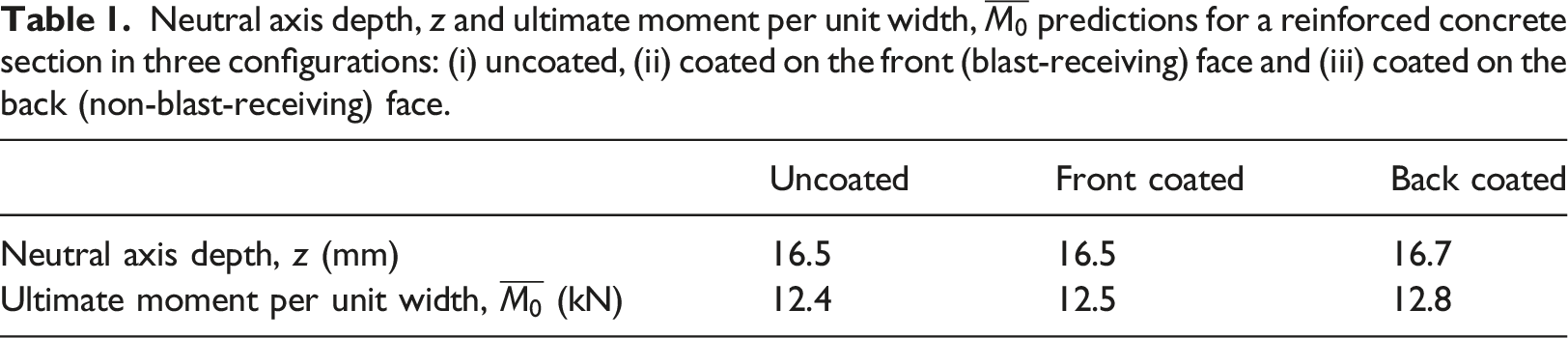
. It is not our intention to represent specific blast cases, instead we choose load cases that allow us to observe regime changes. However, the load cases are the correct order of magnitude to be indicative of realistic blast threats (according to Table 1 in (Fallon & McShane, August 2019)). Figure 2 presents the deflection-time history plots for an uncoated, reinforced concrete section, subject to three different load intensities. Also plotted is the energy dissipated by damage in each case (obtained by interrogating the ALLDMD output in ABAQUS/Explicit (ABAQUS, 2011)). Examination of these plots identifies three distinct regimes of response, defined as follows: • Regime 1: For low impulses, the slab undergoes completely elastic oscillations about a zero-level permanent displacement. In addition, the energy dissipated by damage is zero. This is readily observed in Figure 3(a). • Regime 2: For intermediate impulses, elastic-plastic behaviour is observed, characterised by oscillations about a permanent displacement. Further, the slab achieves a well-defined, stable plateau in energy dissipated by damage, which occurs well after the maximum displacement attained by the slab. (Construction lines on Figure 2(b) illustrate how this is verified for cases when the plateau transition is not sharp.) Figure 3(b) illustrates that the slab exhibits minor damage at the midspan and at the supports. • Regime 3: At higher impulses and pressures, reinforced concrete slabs achieve a plateau in ALLDMD which occurs before the slab has attained its maximum midspan displacement. The level of damage in this regime is severe, as illustrated in Figure 3(c). A mesh sensitivity study has identified numerical stability problems in this regime so it is necessary to define a time at which the slab has failed, beyond which the calculation is deemed inaccurate. This avoids any misleading comparison between stable and unstable numerical solutions. Neutral axis depth, z and ultimate moment per unit width, Central deflection – time and energy dissipated by damage – time histories plotted for an uncoated, reinforced concrete slab subjected to three different blast intensities: (a) p
a
= 1000 kPa, I
a
= 10 Pa s (b) p
a
= 1000 kPa, I
a
= 100 Pa s and (c) p
a
= 1000 kPa, I
a
= 500 Pa s. Damaged slab configurations in each response regime. Plotting contours of tensile damage parameter, d
t
where red contours indicate d
t
> 0.9 which is assumed to be analogous to cracking. Image is taken at the time corresponding to the critical displacement, defined in the text.
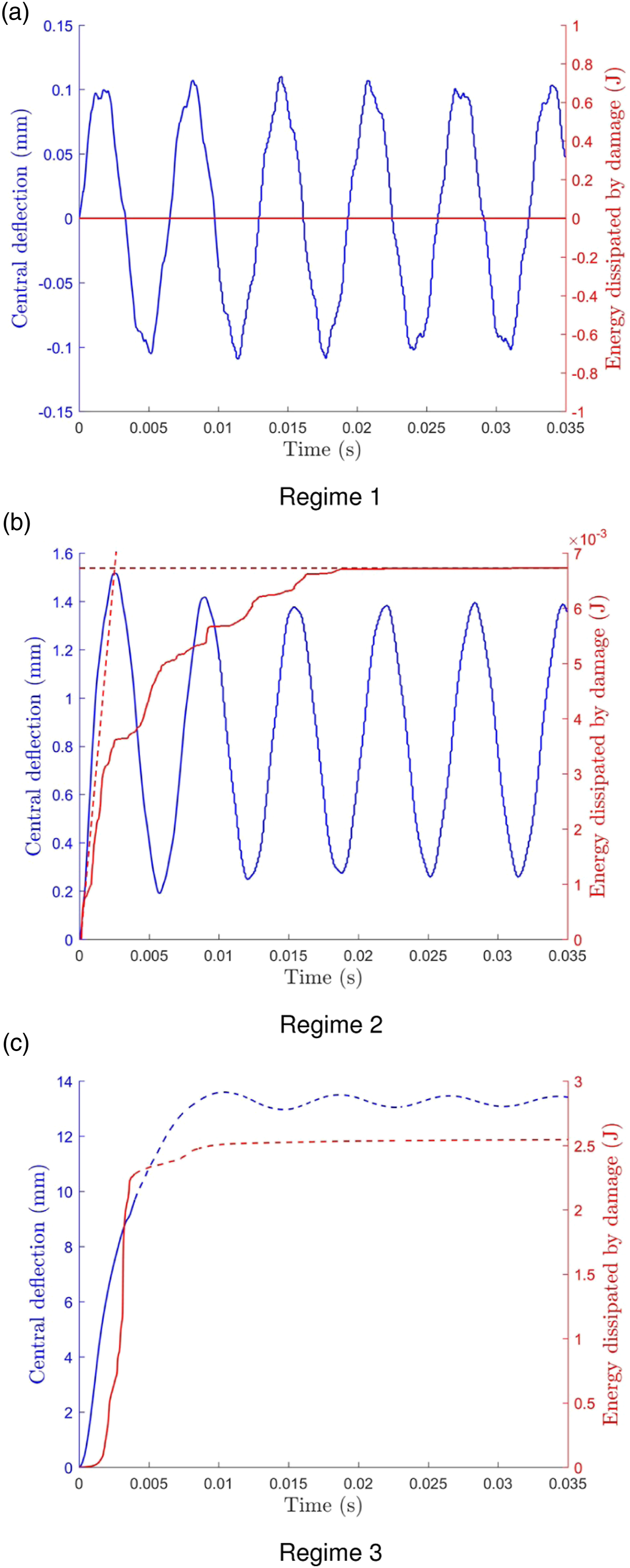
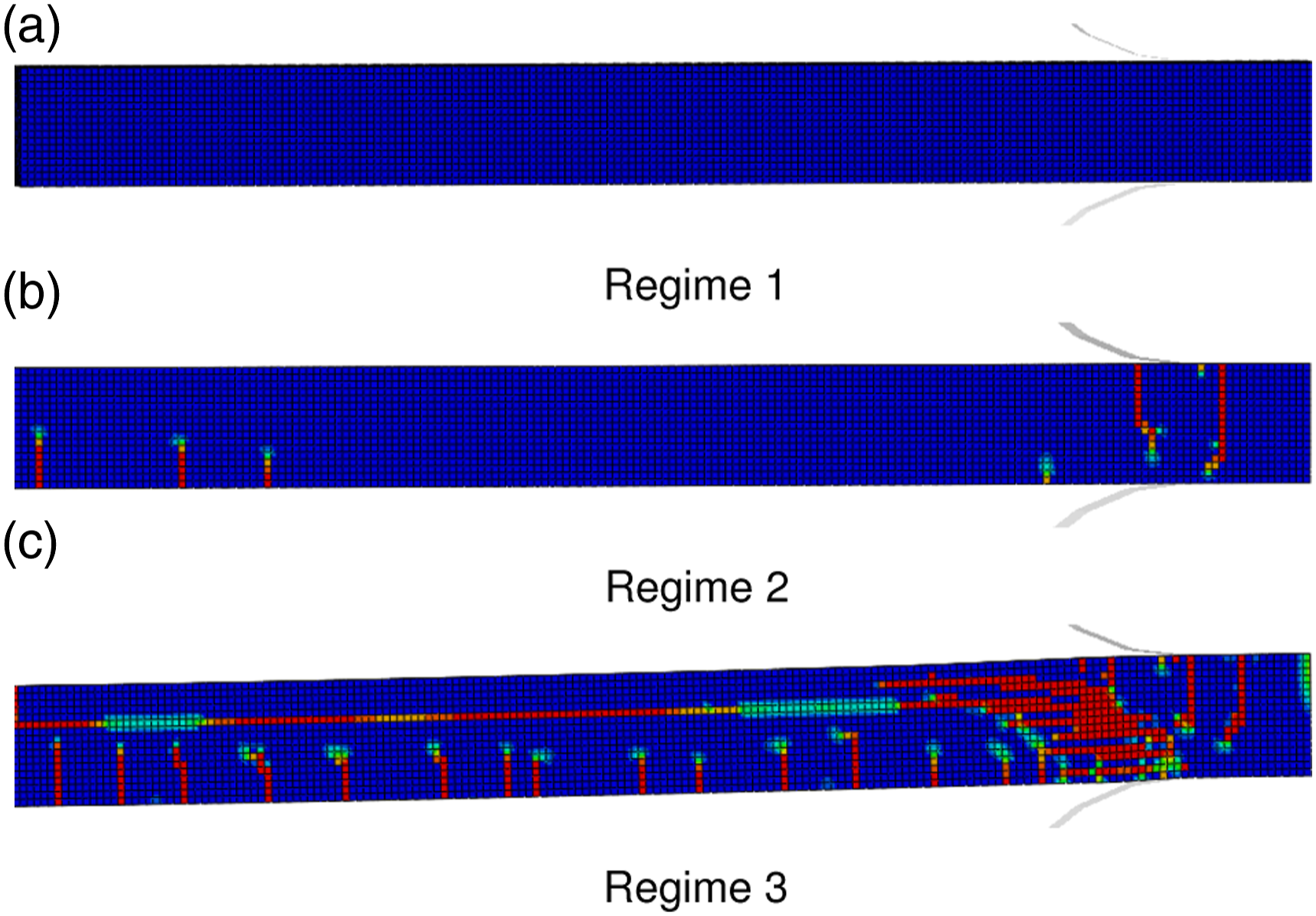
To enable comparison, a critical displacement is defined in each regime as follows: • Regime 1: The critical displacement is taken as the maximum midspan transverse displacement. • Regime 2: The critical displacement is again taken as the maximum midspan transverse displacement. • Regime 3: The knee point (i.e. the sudden drop in gradient) in the ALLDMD versus time graph is chosen as an arbitrary failure time, and the corresponding displacement is noted and recorded as the critical displacement. No physical significance is attached to this indicative value. However, it represents the time at which there is a drop in the rate of further damage propagation, on account of the loss of concrete integrity. In Figure 2(c), the response beyond this point is shown as a dotted line.
Figure 4 presents contours of critical displacement in p
a
− I
a
space for an uncoated, reinforced concrete slab. It is observed that at lower impulses, in the range 101 − 102 Pa s, the level of critical displacement is relatively insensitive to the level of the peak pressure, for a given impulse. At higher impulses (c.103 Pa s), the critical displacement is sensitive to the corresponding peak pressure, with the most severe blast intensities giving rise to the highest critical displacements experienced by the slab. This response map provides a reference against which to compare the effect of the coating, described subsequently. Contour plot mapping the p
a
− I
a
(applied pressure – applied impulse) space for an uncoated, reinforced concrete slab of the geometry described in the text. Contours are isolines of critical displacement in millimetres.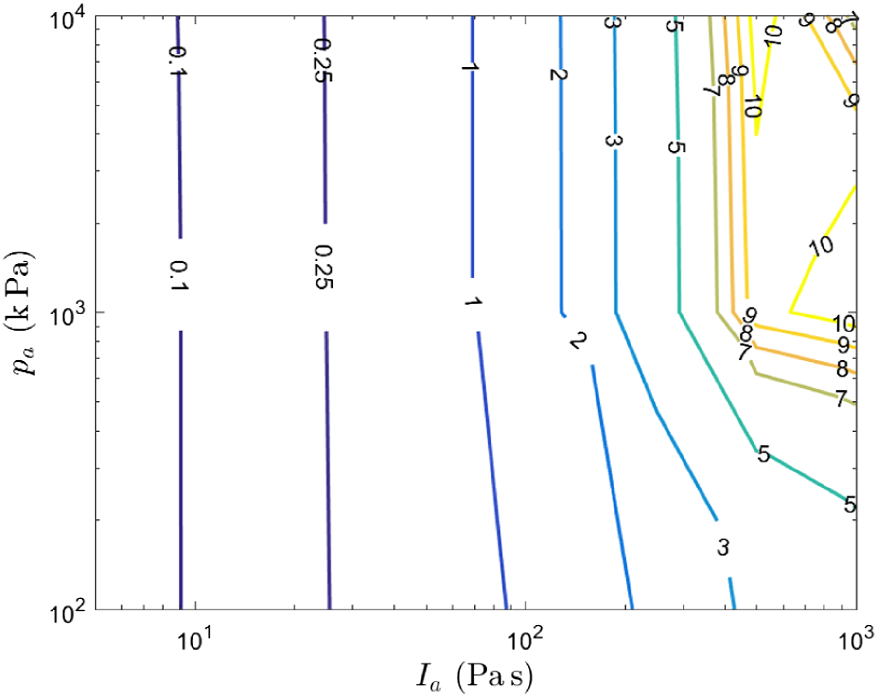
Reinforced versus unreinforced, uncoated concrete
For completeness, the sensitivity of this reference response map to the presence of steel reinforcement is briefly assessed. Figure 5 considers slices through a p
a
− I
a
diagram at three values of applied peak pressure, p
a
for an uncoated concrete slab. The critical displacements for unreinforced and reinforced configurations are compared. Critical displacement, u
crit
variation with applied impulse, I
a
at three different peak pressures, p
a
. Results are plotted for uncoated, reinforced and unreinforced concrete slabs.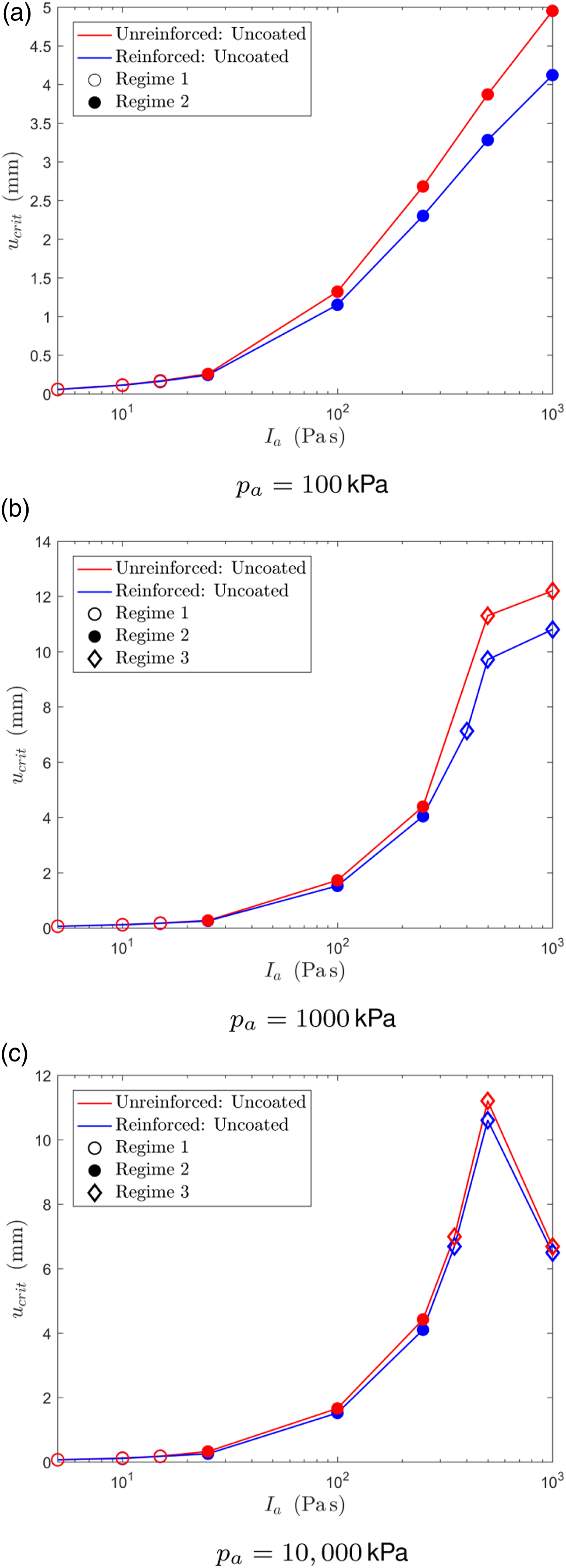
Generally, it is observed that the critical displacement increases with increasing impulse. However, for high intensity blasts (higher peak pressure, p
a
and impulse, I
a
), the critical displacement starts to fall with increasing I
a
. This is because slab failure is occurring earlier in the slab’s motion, with increasing impulse. The presence of reinforcing bar has only a small effect in Regimes 1 and 2 which will be explained by analytical reasoning subsequently. In Regime 3, comparison is made difficult given that the simulation must be halted at an early time step, before severe concrete damage leads to mesh sensitivity. Instead, in Figure 6, central deflection-time histories are compared for uncoated, unreinforced and reinforced concrete slabs exhibiting a Regime 3 response. The unreinforced slab fails to reach a permanent deflection, in contrast to the reinforced case where the presence of the reinforcing bar serves to stabilise the deflections of a severely damaged slab. However, the overall picture remains unaffected, since the critical displacement is defined well before this effect becomes significant. Thus, the following investigation will focus only on reinforced concrete. Central deflection - time history for an uncoated, reinforced and unreinforced concrete slab subjected to p
a
= 1000 kPa and I
a
= 500 Pa s, behaving in response Regime 3. A critical displacement is defined, beyond which, the deflection is shown as a dotted line.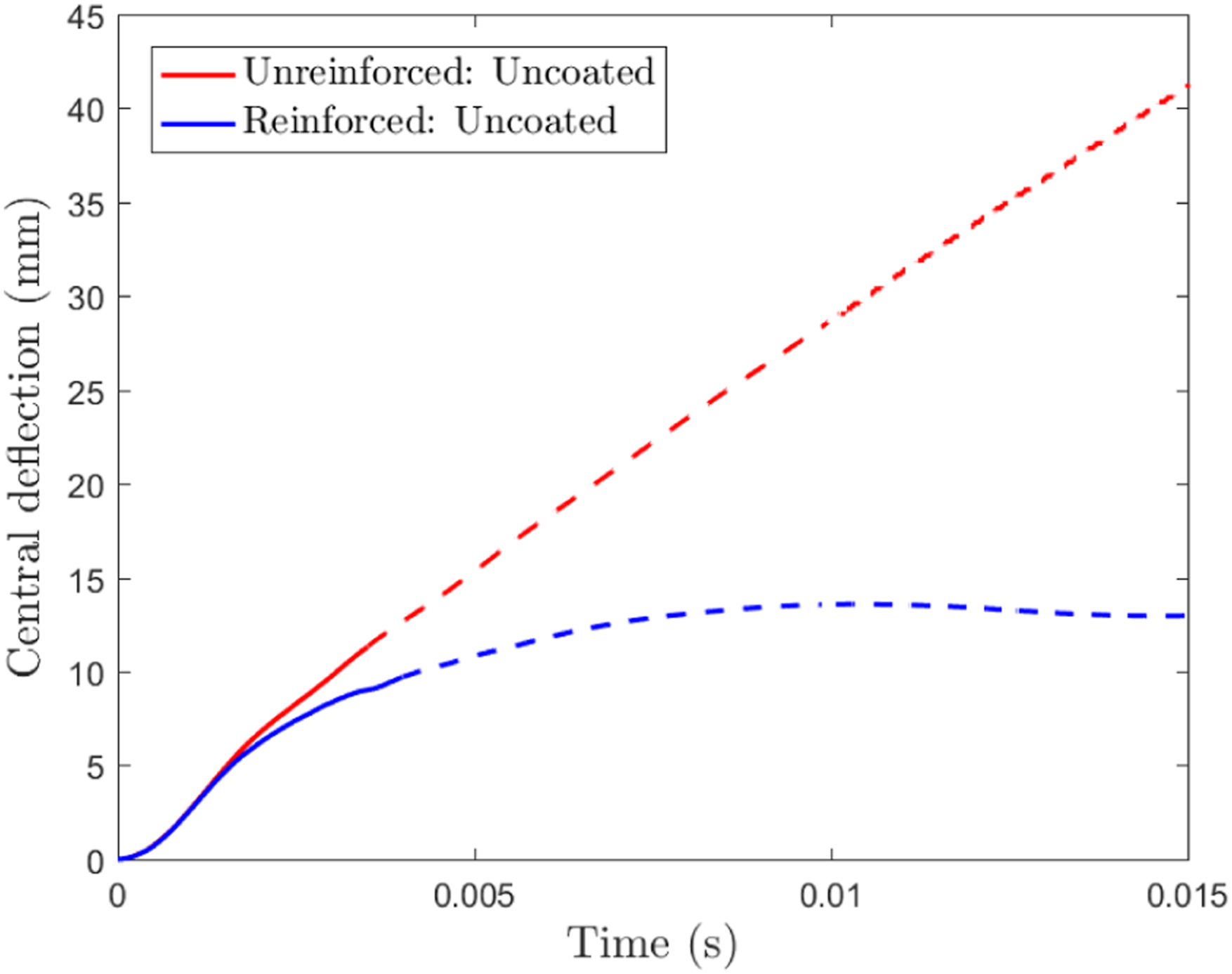
Response regimes of coated, reinforced concrete
With the response regimes of uncoated, reinforced concrete slabs established, the influence of the addition of an elastomer coating is now interrogated. Three configurations are considered: (i) uncoated, (ii) coated on the blast-receiving (front) face and (iii) coated on the non-blast-receiving (back) face. The numerical modelling strategy is as described previously. Figure 7 plots the variation in critical displacement, u
crit
with applied impulse, I
a
for three values of peak applied pressure, p
a
. Critical displacement, u
crit
variation with applied impulse, I
a
at three different peak applied pressures, p
a
. Results are plotted for a reinforced concrete slab in three configurations: (i) uncoated, (ii) front coated (on the blast-receiving face) and (iii) back coated (on the non-blast-receiving face).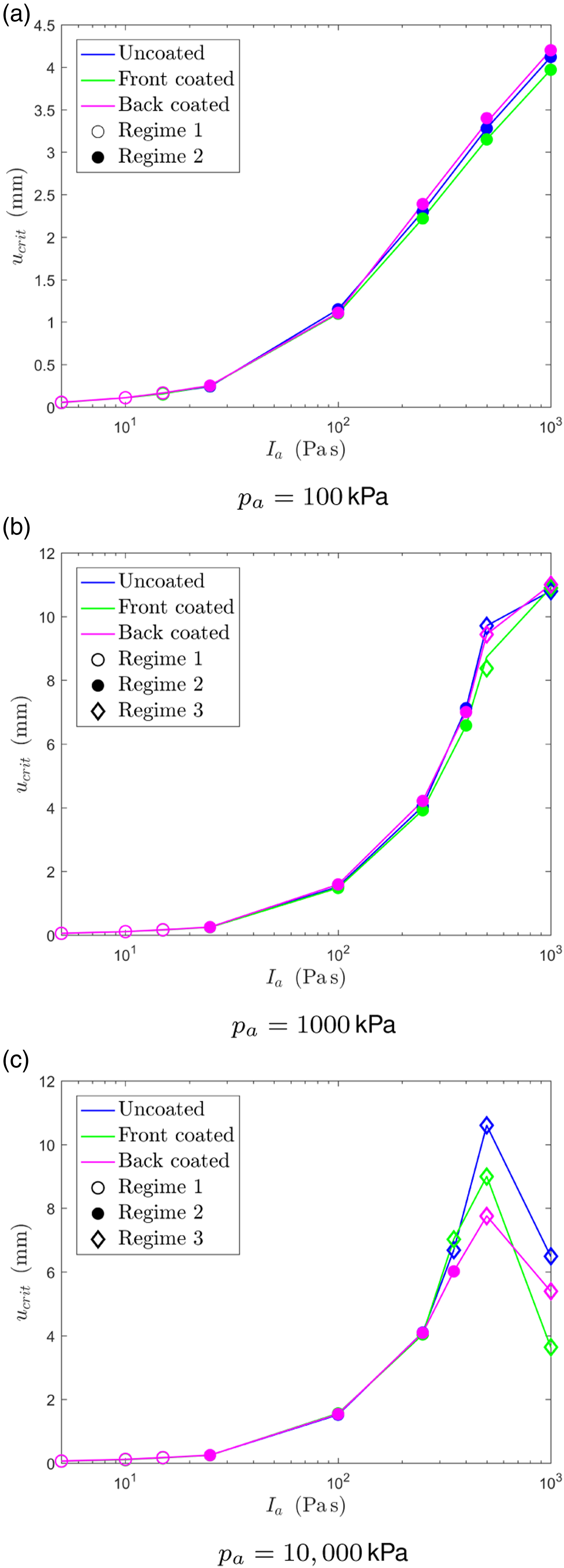
First, it is observed that for slabs behaving in Regimes 1 and 2, at the lower load intensities, the addition of a 5 mm elastomer coating to either the blast-receiving or non-blast-receiving face contributes a negligible effect to the critical displacements experienced. There is some evidence that coating on the front face, in Regime 2, is most beneficial in terms of reducing u crit . Future studies will seek to assess the interplay between the additional mass contribution and any pulse-shaping or mechanical coating benefits in these low intensity regimes. However, the effect here is a minor one and furthermore, the addition of the coating does not affect the boundary between Regimes 1 and 2, in terms of applied impulse.
At higher load intensities, in Regime 3, interpretation of FE results is hindered by severe concrete damage which leads to inherent mesh sensitivity. However, significant effects can be observed when considering the critical displacements and impulses close to the boundary between Regimes 2 and 3. Figure 8 plots the displacement-time history for the slab when subjected to a blast intensity, p
a
= 10,000 kPa and I
a
= 350 Pa s. This corresponds to a load case that gives rise to a slab response in the vicinity of the Regime 2–3 boundary. For the uncoated RC slab and that coated on its blast-receiving face, the slab exhibits a Regime 3 response, whereas when coated on its non-blast-receiving face, it behaves with a Regime 2 response. This shift from Regime 3 to Regime 2 behaviour results in a significant reduction of 48% in the permanent displacement experienced by the slab. It is observed that in Regime 3, one mechanism of failure is tensile cracking, propagating perpendicular to the rear, tensile face of the slab. The other mechanism is extensive damage locally at the supports. The polymer appears most effective at suppressing this particular failure mechanism. Central deflection – time history for a reinforced concrete slab subjected to p
a
= 10,000 kPa and I
a
= 350 Pa s. Three configurations are considered: (i) uncoated, (ii) front coated (blast-receiving face) and (iii) back coated (non-blast-receiving face). A failure time is defined in the text, beyond which, the deflection is shown as a dotted line.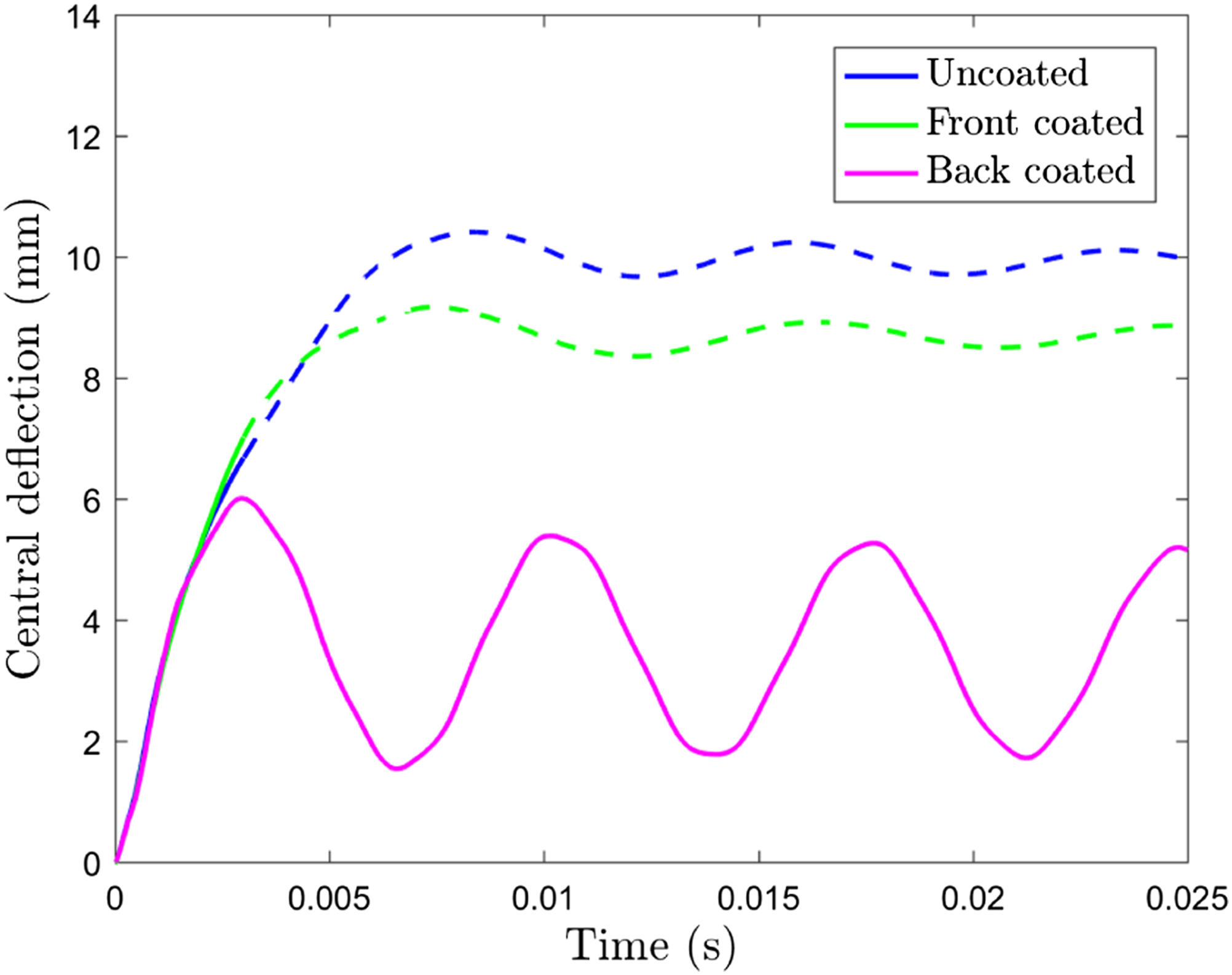
Analytical modelling
In this section, analytical models are used to support the interpretation of the FE predictions and to help explain the predicted sensitivity to the elastomer coating in each of the identified regimes.
Regime 1
Regime 1 is characterised by purely elastic bending of the one-way slab. To capture this, Timoshenko et al.’s (1974) theory on the transverse vibrations of an elastic beam is employed. An impulsive load is assumed, with an instantaneous transverse velocity, V
inst
applied along the length of the span. This assumption is valid for cases when the blast pulse duration, t
i
is much shorter than the structural response time i.e. when the peak pressure, p
a
is large for a given impulse, I
a
. The instantaneous velocity, V
inst
is related to the imparted impulse, I
a
by equation (4) (Xue and Hutchinson, 2003)
First, a simply supported span (of length, 2L, axial co-ordinate, x and transverse deflection, y) is considered. The transverse vibrations may be described by equation (5), derived from the theory in (Timoshenko et al., 1974)
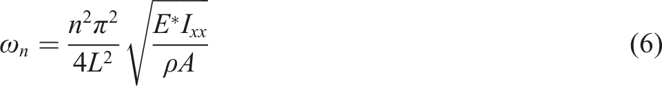
Alternatively, a different support condition may be considered. The transverse vibrations of a span with both ends clamped (or fixed) may also be derived using Timoshenko theory (Timoshenko et al., 1974)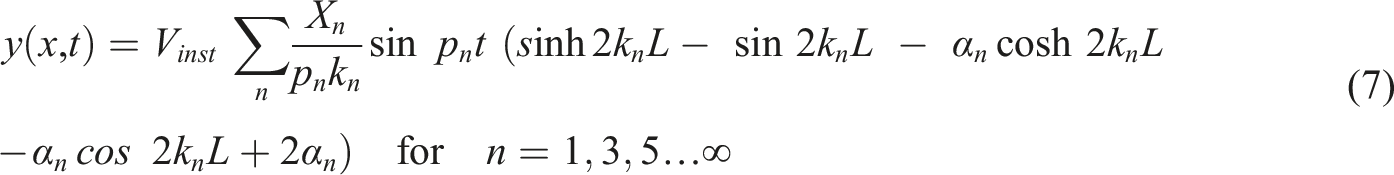


In the elastic regime, the effect of a 5 mm thick elastomer coating can be accounted for using the transformed section approach, whereby the elastomer coating is transformed to an equivalent area of concrete in the ratio of the elastic moduli, ϕ e = E e /E0. For a reinforced concrete section of elastic modulus, E0 = 28.3 GPa coated with an elastomer of elastic modulus, E e = 80 MPa, the modular ratio, ϕ e = 2.8 × 10⁻³. Thus, the addition of an elastomer coating has a negligible effect on the position of the neutral axis and the value of the second moment of area, I xx of the section. Indeed, for any realistic coating and section depths, the effect remains negligible. The method of transformed section can also be used to explain why there is such a small difference in the Regime 1 deflections exhibited by the reinforced and unreinforced sections in Figure 5. The area of steel rebar, A s is converted to an equivalent area of concrete using the modular ratio, ϕ s = E s /E0 = 7.1 where the elastic modulus of steel, E s = 200 GPa. The addition of steel rebar has a small (less than 10%) effect on the neutral axis position and second moment of area.
Thus, equations (5)–(9) can be used to provide analytical estimates for the maximum transverse displacement of both coated and uncoated spans. Considering a 50 mm thick, reinforced concrete section of the geometry described previously, a comparison between the FEA results and analytical predictions is presented in Figure 9. Comparison between maximum central deflection predicted by the FE model and analytical theory for reinforced concrete spans at low blast intensities. Three configurations are considered: (i) uncoated, (ii) front coated (blast-receiving face) and (iii) back coated (non-blast-receiving face). Analytical predictions are presented for two support conditions: simply supported (s.s.) and clamped-clamped (c.c.). The dotted line at I
a
= 19 Pa s indicates the analytically predicted boundary between Regimes 1 and 2. ◦ represents Regime 1 behaviour and • is Regime 2.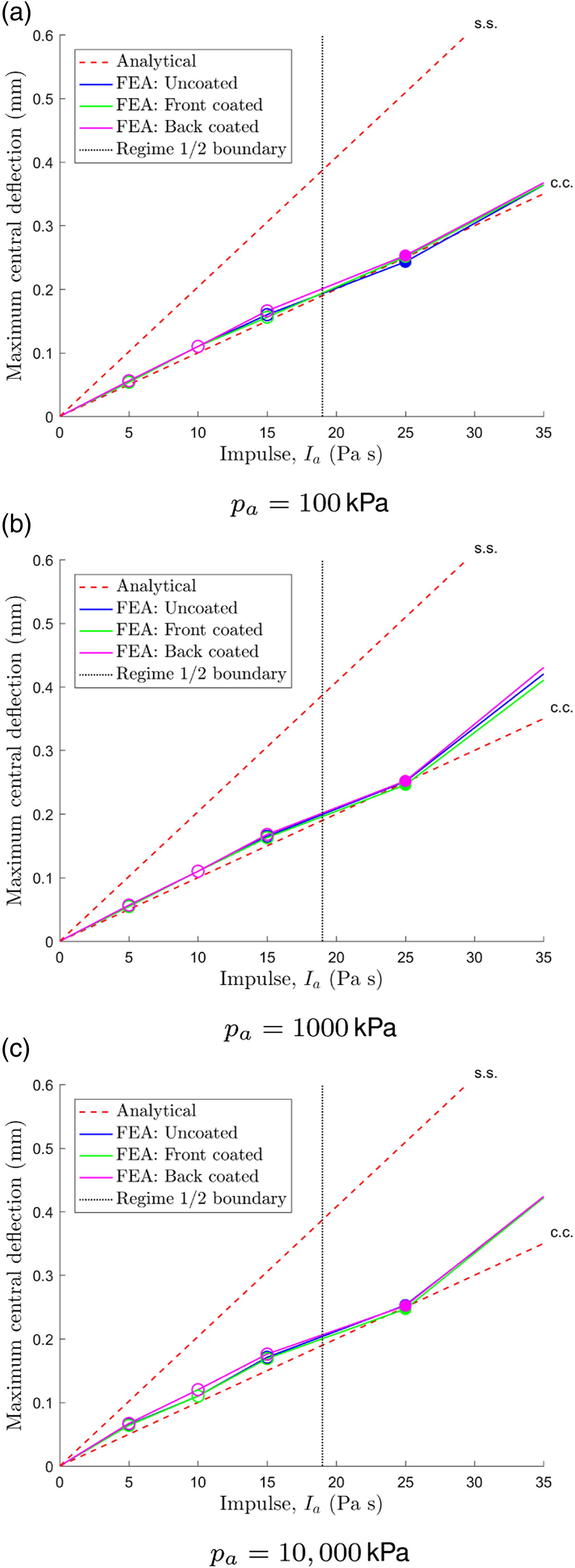
The clamped-clamped span analysis predicts deflections which are in very close agreement with the FEA results. In this low blast intensity regime, the simply supported model consistently overpredicts span deflections. Nevertheless, both models are sufficient to explain the insensitivity of the concrete section to the coating in Regime 1, as observed in the FE analysis.
Regime 1–2 transition
Extending the relatively simpler analysis for the simply supported span, the relationship presented in equation (10) is obtained for the dynamic stress on the cross-section, σ(x, t) at a distance, z from the neutral axis, at an axial position, x and time, t
Using equation (10), the maximum stress on the cross-section can be calculated at the extreme fibre, z = 25 mm. Assuming that purely elastic behaviour ceases when the maximum stress on the cross-section reaches the value of the concrete tensile strength, σt0 = 4.2 MPa; a script can be implemented to find the instantaneous velocity, V inst and hence the impulse, I a when this criterion is first reached. This provides an analytical estimate for the boundary between Regimes 1 and 2. For the reasons described previously, the addition of an elastomer coating has a negligible effect on the maximum stress experienced by the reinforced section in the elastic regime. Thus, the critical velocity in Regime 1 for both coated and uncoated cases is V inst = 0.15 m s−1 and the critical impulse is I a = 19 Pa s. This predicted boundary is marked on the plots in Figure 9. It is found to be a good match to the FEA which predicts a Regime 1–2 transition between I a = 15 − 25 Pas. Assuming the critical location to be at the midspan, the critical impulse is calculated to be the same for both simply supported and clamped spans (it is noted however that in the clamped case, the critical location may well be at the supports; in this case a lower critical impulse, I a = 14 Pa s is predicted).
Regime 2
Regime 2 behaviour is characterised by oscillations about a permanent level of deflection. The transition from the purely elastic Regime 1 is accompanied by the onset of damage. To interrogate this regime, Jones’ (1989) solutions for the deformation of a rigid-perfectly plastic beam, loaded impulsively are employed. Jones justifies the rigid-perfectly plastic analysis by assuming that elastic effects can be neglected when the external dynamic energy i.e. the kinetic energy, K
e
is much larger than the maximum strain energy, S
e
that the span can absorb elastically. As before, if it is assumed that the span acquires an instantaneous velocity, V
inst
when loaded impulsively, the following non-dimensional group, E
r
provides an indication of when elastic effects can be neglected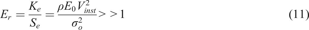
Jones (1989) provides the following prediction for the permanent transverse displacement, u
perm
of a simply supported span, of length, 2L loaded impulsively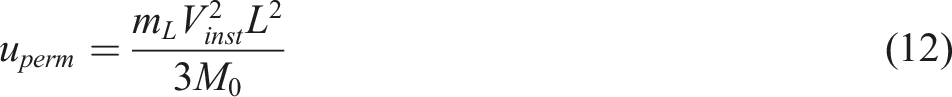
Further, Jones’ (1989) solution for a clamped-clamped span loaded impulsively is also considered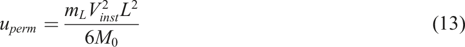
One of the inherent assumptions in Jones’ theory (Jones, 1989) is that the section is ductile – this is not the case for an unreinforced concrete section which undergoes brittle failure. Therefore, Jones’ solutions are not valid in this case.
To obtain a value for the collapse moment, M0 for a reinforced concrete section, the ultimate limit state is considered where two simplifying assumptions are made: the tensile strength of the concrete is assumed to be zero and the concrete compressive behaviour can be approximated using an equivalent rectangular stress block, illustrated in Figure 10. For simplicity, a mean stress of 0.6σ
cu
is assumed based on the BS8110 recommendation (British Standards Institution BS 8110-1:1997: Structural use of concrete. Code of practice for design and construction, 1997) (where σ
cu
is the compressive strength of the concrete, 39.5 MPa). Assuming that the steel yields at the same time as the concrete fails (i.e. a balanced cross-section), longitudinal equilibrium for the uncoated section in Figure 10(a) gives the neutral axis depth, z Schematic of a reinforced concrete section at its ultimate limit state in three configurations: (a) uncoated, (b) coated on its blast-receiving face and (c) coated on its non-blast-receiving face. The stress, σ profiles are presented to illustrate how the ultimate moment, M0 can be derived by equilibrium.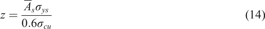
Moment equilibrium gives the ultimate moment per unit width of the section:
d is the effective depth of the cross-section (to the reinforcing bar), 40 mm;
The addition of a coating to either the blast-receiving (Figure 10(b)) or non-blast-receiving (Figure 10(c)) face introduces an additional longitudinal stress equal to, εe Ee b he. E
e
is the Young’s Modulus of the elastomer which is assumed to be 80 MPa (measured in (Fallon & McShane, August 2019)) and h
e
is the depth of the elastomer coating, 5 mm. The strain in the elastomer, εe can be estimated given the ultimate compressive concrete strain, εcu = 0.0035 and the steel yield strain, εy = 0.003. This extra term has only a small influence on the neutral axis position and
The predictions for the permanent displacement, u
perm
of simply supported and clamped-clamped spans in their uncoated, front coated and back coated configurations are compared with FEA results in Figure 11. Comparison between midspan permanent displacement, u
perm
predicted by the FE model and analytical theory. Analytical predictions are presented for two support conditions: simply supported (s.s.) and clamped-clamped (c.c.). Three configurations are considered: (i) uncoated, (ii) front coated (blast-receiving face) and (iii) back coated (non-blast-receiving face). ◦ represents Regime 1 behaviour, • is Regime 2 and ⋄ is Regime 3.
For an intermediate value of p a (Figure 11(b)) there is very good agreement between the FEA results and analytical predictions. The FE results fall between the simply supported and clamped-clamped analytical predictions which matches the boundary condition employed in the FE model (discussed previously). For this load case, the results sit consistently within Regime 2, and hence Jones’ theory is effective at predicting permanent deflections. Furthermore, the analytical model confirms the insensitivity to the coating in Regime 2.
For the highest peak pressure (Figure 11(c)) there is also good agreement between the analytical model and the FE for results within Regime 2. As the impulse is increased, moving into Regime 3, the discrepancies increase. The FE results predict that the boundary between Regimes 2 and 3 lies between I a = 350 − 500 Pa s (for p a = 10, 000 kPa).
For the lowest value of p a (Figure 11(a)), although the span is responding in Regime 2, the analytical model provides a good prediction of deflections only at the lowest values of impulse. High impulse, low peak pressure load cases correspond to a large blast duration, t i . In these cases, the value of t i is no longer small with respect to the structural response time. As a consequence, the impulsive loading assumption in the analytical model ceases to be realistic.
Regime 3
The Regime 3 response is dominated by concrete damage. The slab undergoes continued plastic deformation and damage throughout the FE calculation. Note that damaged elements are not deleted from the FE model, which may affect the reliability of the predictions when the volume of damaged concrete is significant. As described previously, the simulations must therefore be halted at a time step corresponding to a defined critical level of damage. Analytical methods are also limited in their ability to predict the extensive cracking and damage.
However, some insight is gained by qualitatively examining the damaged slab configurations at the time at which the critical displacement (defined previously) is reached. Figure 12 illustrates that by increasing the blast intensity, within Regime 3, a switch in the pattern of damage is observed to one which is dominated by failed elements near the support region (Figure 12(b)). Note that although the damage pattern changes, the behaviour of both slabs is consistent with the Regime 3 response characteristics illustrated in Figure 2(c). The damage pattern in Figure 12(b) indicates that at the highest blast intensities considered, the slab undergoes a transverse shear failure mechanism at the supports. This has been widely reported in the literature for RC structures subjected to high intensity impulsive loading (Trivedi and Singh, 2013; Zineddin and Krauthammer, 2007). In the following section, an analytical technique is described which can be used to investigate the effect of a polymer coating on this particular failure mechanism. Damaged slab configurations for an uncoated, reinforced concrete slab subjected to: (a) p
a
= 1000 kPa and I
a
= 1000 Pa s, (b) p
a
= 10, 000 kPa and I
a
= 1000 Pa s. Plotting contours of tensile damage parameter, d
t
where red contours indicate d
t
> 0.9 which is assumed to be analogous to cracking. Images taken at the time corresponding to the critical displacement (defined in the text): (a) t = 2.2e-3s, (b) t = 9.0e-4s.
Transverse shear failure
To interrogate the transverse shear failure response, the shear capacity of reinforced concrete is first estimated. The shear resistance of reinforced concrete (without internal shear reinforcement) arises due to a complex interaction between aggregate interlock, concrete compressive strength and dowel action of the longitudinal steel reinforcing bars. Various empirical relationships based on experimental data have been proposed to approximate the shear capacity of a reinforced concrete section. Eurocode 2 (European Committee for Standardization (CEN) BS EN 1992-1-1: 2004: Eurocode 2: Design of concrete structures, 2004) provides the following relationship for the design shear resistance per unit width, 
σ
ck
≈ 0.8σ
cu
; the characteristic concrete cylinder compressive strength in MPa;
Thus,
When the coating is applied to either the blast-receiving or non-blast-receiving face of a RC section; there is an additional contribution to the shear strength. This contribution is estimated from the experimental shear punch test performed on a commercially available sample of polyurea/polyurethane elastomer at nominal strain rates, 
A first order estimate of the total shear capacity per unit width of a coated, reinforced concrete section is therefore;
Analytical predictions, using the theory in (Jones, 1989), for the transverse shear failure of a simply supported, reinforced concrete span of the geometry described in the text (assuming failure occurs at k = 1).
Table 2 shows that, as a result of the relatively low resistance of the concrete to this shear failure mode, a polymer coating may provide significant additional resistance in this mode of deformation. The key elastomer properties required to achieve this protective benefit appear to be high ductility and a large shear strength, τ e .
This result is difficult to verify using the current FE modelling strategy, as it does not capture the response post significant concrete damage. However, it is noted that the differences in critical displacement between coated and uncoated spans are most significant in Regime 3 where the coated structures begin to show a performance benefit.
The predicted benefit is also supported by early blast trials on masonry wall structures (which might be considered analogous to a concrete span that has undergone extensive cracking) which also showed benefits of polymer coating (Baylot et al., 2005; Davidson et al., 2004). In these cases, the masonry block wall relies on the membrane action of the elastomer under blast loading to prevent collapse. Furthermore, Raman et al. (2012) studied a polyurea-coated RC panel of similar dimensions to the slab in question, subjected to a peak reflected pressure, p a = 2477 kPa and impulse, I a = 518 Pa s. This load case would result in a Regime 3 response for our slab. Raman et al. (2012) reported a significant protective coating benefit in this regime, noting that the addition of a 4 mm polyurea layer reduced slab deflections by more than 40%.
Alternative numerical techniques are required to interrogate Regime 3 behaviour in order to confirm the protective function of the polymer here.
Discussion: response map
Figure 13 presents a summary of the response regimes of a reinforced concrete slab of the geometry described previously, when uncoated and coated with a 5 mm elastomer on its non-blast-receiving face. Also plotted are the analytical predictions of the Regime 1 - 2 boundary and the impulse for transverse shear failure. The regime responses predicted by FEA of a reinforced concrete section (a) uncoated and (b) 5 mm coated on its non-blast-receiving face. ◦ represents Regime 1 behaviour, • is Regime 2 and ⋄ is Regime 3. The regime boundaries predicted by the proposed analytical models for a simply supported boundary condition are also plotted.
The analytical models are effective at predicting the regime transition for Regimes 1–2 and give a good indication for an upper bound on Regimes 2–3. The analytical models and FE predictions also agree with regard to the coating influence in each regime. For a span exhibiting a Regime 1 or 2 response, the coating influence is negligible. Instead, it appears that the coating serves its greatest protective benefit in Regime 3, when the concrete is severely damaged. For load cases with an impulse close to the Regime 2–3 boundary and above, an elastomer coating appears to provide a protective effect in terms of reducing deflections and delaying global failure. Note that severe concrete damage, coupled with lack of element deletion, caused numerical stability problems in Regime 3. However, analytical modelling illustrated how the polymer coating may provide significant additional resistance against the shear failure mode and qualitative observations of the damaged slab configurations agreed with this. Early blast trials on masonry wall structures (Baylot et al., 2005; Davidson et al., 2004) in which the masonry relied on the membrane action of the elastomer coating to prevent collapse adds further evidence that the polymer coating is most effective in Regime 3, when the concrete is severely damaged.
Conclusions
Numerical and analytical modelling is used to ascertain how the response of thin, one-way unreinforced and reinforced concrete slabs varies with simulated blast load intensity and the presence of an elastomer coating. The following conclusions are established: • Three response regimes of thin, one-way slabs are identified, each characterised by span deflections and energy dissipated by damage. • In Regime 1, the slab behaves purely elastically and thus an analytical technique based on Timoshenko et al.’s (1974) theory on the transverse vibrations of an elastic beam is proposed. Deflections are predicted well assuming clamped-clamped boundary conditions, and the model proves capable of predicting the boundary between Regimes 1 and 2 with accuracy. The slab is found to be insensitive to polymer coating in this regime. • Regime 2 is characterised by oscillations about a permanent displacement and the attainment of a plateau in damage energy dissipated (that occurs well after the maximum slab deflection). Jones’ (1989) rigid-plastic solutions agree well with the FE predictions of permanent displacement in this regime. Once again, the slab remains relatively insensitive to the presence of an elastomer coating. • At higher blast intensities, in Regime 3, the slab undergoes continued plastic deformation and damage. A critical displacement is therefore defined, to identify the time at which the slab fails. In this regime, a greater sensitivity to the presence of a polymer coating is identified. • By probing the regime boundary between Regimes 2 and 3, the FE results indicate a substantial reduction in deflections, by up to 48% for coating on the back (non-blast-receiving) face. With the coating on the back face, the slab exhibits a Regime 2 response, whereas when uncoated, or coated on its front face, it behaves in Regime 3. • At the highest load intensities, the damage patterns observed in the FEA indicate a shift in failure mechanism to one dominated by transverse shear failure at the supports. An analytical model for shear failure indicates that the coating can offer a significant protective benefit against this particular failure mechanism due to its high shear strength and ductility.
Footnotes
Declaration of conflicting interests
The author(s) declared no potential conflicts of interest with respect to the research, authorship, and/or publication of this article.
Funding
The author(s) disclosed receipt of the following financial support for the research, authorship, and/or publication of this article: The authors are grateful to the George and Lillian Schiff Foundation of the University of Cambridge for financial support.