
Abstract
Maraging steel is a low carbon steel known for its ultra high-strength after heat treatment. In combination with Additive Manufacturing (AM), the properties of maraging steel indicate potential to enable complex geometries and improved performance-to-weight ratios for ballistic protection. This study investigates the ballistic performance of AM maraging steel monolithic plates and profile panels fabricated by powder bed fusion. The mechanical properties of the maraging steel, both in the as-built state and after heat treatment, were revealed through quasi-static and dynamic tests in three different directions with respect to the build direction. Metallurgical studies were also conducted to investigate the microstructure of the material both before and after testing. The ballistic perforation resistance of the maraging steel samples was disclosed in a ballistic range by firing 7.62 mm APM2 bullets towards the different target configurations. Ballistic limit curves and velocities were obtained, demonstrating that the thickest heat-treated AM maraging steel plate has a particularly good potential for ballistic protection. The hard core of the armour piercing bullet broke in all tests and occasionally shattered during tests with heat-treated targets. However, due to the severe brittleness of the material, the targets showed significant fragmentation in some cases and most significantly for the profile panels.
Keywords
Introduction
Research has shown that the ballistic perforation resistance of steel plates is an almost linear increasing function of the material’s yield strength (Børvik et al., 2009). Thus, the use of advanced high-strength materials with optimal ballistic capacity can lead to improvements in the performance-to-weight ratio of monolithic armour plates (Demir et al., 2008; Kasilingam et al., 2019; Madhu and Bhat, 2011; Ranaweera et al., 2020). Historically, the light-weighting of armour systems has relied on areal density reduction, which after a certain level must be reinforced with advanced materials to achieve the necessary ballistic capacity. Materials with high strength have, however, typically less flexible manufacturing methods, limiting the opportunity for complex geometry and areal density reduction (Børvik et al., 2005). In recent years Additive Manufacturing (AM), a fabrication process based on the successive addition of material layer by layer, has introduced capacity for weight-saving intricate geometries to advanced materials. AM possesses a large unrealised potential in the field of ballistic protection, with the largest drawback being the uncertainty surrounding the mechanical properties of AM materials under impulsive loading. Promisingly, a recent study by Kristoffersen et al. (2020) demonstrated marginal discrepancy in ballistic response between AM and traditionally die-cast aluminium plates.
Novel metal AM processes developed by for example Vyatskikh et al. (2018) are able to achieve complex geometries with a resolution in the nano-scale. However, the most common AM techniques for metallic materials, powder bed fusion (PBF) and direct energy deposition (DED), produce components with unit cell sizes in the range 10–100 μm. PBF and the subcategory selective laser melting (SLM) involve the local melting of metallic powder with a high energy laser directly from a computer-aided design (CAD) file. The process is controlled by parametres such as laser power, laser speed and powder particle diametre that are fine-tuned to produce parts with comparable or often superior mechanical properties to traditional manufacturing methods (Akram et al., 2018; Frazier, 2014; Vock et al., 2019). This can be attributed to the fine grain structure left by laser melt pools of diametre close to 1 μm formed by exceptionally high cooling rates (from
The material most commonly used for AM in aerospace and tooling products is maraging steel, known for its superior strength and hardness with reduced loss of toughness and malleability. Maraging steel is a special class of low-carbon steel with characteristics that make it particularly well suited to AM techniques. For example, the high cooling rates imposed by PBF that give AM maraging steel optimal strength would cause extreme hardness and breakages in high carbon steels (Tan et al., 2017). The mechanical properties of SLM maraging steel substantially improve after heat treatment. After the industry standardised heat treatment of 490 °C for 6 h, the micro-hardness and tensile strength significantly increase and as a consequence the fracture elongation and impact toughness are reduced (Bai et al., 2019). The compromise of heat-treating AM maraging steel is therefore obtaining ultra high-strength while worsening ductility. This effect is well established and is consistent throughout the many studies conducted, however, the effect of specific temperature and duration of heat treatment on ductility are debated in the literature (Bai et al., 2019; Jägle et al., 2014, 2016; Tan et al., 2017). Furthermore, it has been shown that laser scanning speed and layer thickness have significant impact on the hardness and relative density of the finished product (Kempen et al., 2011).
The superior mechanical strength achieved after heat treatment makes AM maraging steel a strong candidate for protection against ballistic impact. The apparent potential to optimise for ductility through heat treatment while retaining ultra high tensile strength is an exciting prospect for this application and does not seem to have been explored yet. It is also proposed that the freedom associated with AM fabrication could transform the weight efficiency of protective components against small-arms projectiles. Also, on-site repair or reinforcement made possible with flexible AM methods could improve adaptability and safety of for example overseas operations (Børvik et al., 2008a, 2008b; Ma and Liew, 2013; Ngo et al., 2018).
It was therefore the aim of this study to investigate AM maraging steel under ballistic impact where it is subjected to large strains, high strain rates and possible temperature softening due to self-heating. Particular attention was paid to the effect of heat treatment on the material’s mechanical behaviour and ductility. To this end, ballistic impact tests were carried out on a number of as-built and heat-treated AM plates of two different thicknesses and truss-like components. The results from these tests were reported and supported by both an examination of the microstructure of the material and a comprehensive programme of material characterisation tests at different strain rates. It was found that the thickest heat-treated maraging steel plate had a great potential in ballistic protection. The hard core of the APM2 bullet broke in all tests, and in some of the tests it shattered completely. However, due to the severe brittleness of the material, the targets showed significant fragmentation in some cases, and most so for the profile plates. Thus, more work is required in order to increase the ductility of AM maraging steel targets through a proper heat treatment before it can be used with confidence in ballistic protection, but the potential for such solutions was found to be significant.
Materials
Maraging steel 1.2709
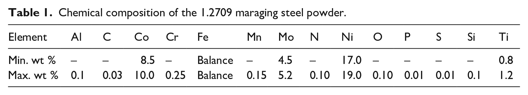
Maraging steels are iron-nickel alloys well suited for AM. The most common alloy, 1.2709, is offered by all metal AM machine manufacturers and several metallurgical companies. The chemical composition of this powder is listed in Table 1. 1.2709 maraging steel is relatively soft (30–35 HRC) in its solution annealed state, but a hardness in the range of 48–58 HRC can be obtained through ageing. It can be polished and nitrated to achieve fine surface structures and increased surface hardness, and coated using chemical vapour deposition (CVD). The material has low thermal expansion (
Chemical composition of the 1.2709 maraging steel powder.
Maraging steels derive their strength not from carbon content, but from providing a high number density of nanometre-sized intermetallic precipitates in a martensitic matrix (Casati et al., 2016; Jägle et al., 2014). Conde et al. (2019) reported that as-built 1.2709 has a non-homogeneous microstructure with 4 vol% retained austenite and no discernible secondary precipitation. The AM parts demonstrated higher hardness than the non-AM parts, however, the cyclic heating during the building process clearly is not sufficient to nucleate significant precipitate formation. Subsequent ageing is thus necessary to provide the hardest condition with the highest strength.
Casati et al. (2016) evaluated the effect of ageing temperature and duration on tensile performance. The tests revealed that the ageing process dramatically increases strength while ductility falls compared with the as-built samples. It is suggested, however, that over-ageing leads to martensite-to-austenite reversion and to a decrease in mechanical strength. Therefore, the ageing procedure appears to be more sensitive to temperature than time, a conclusion supported by other sources (Bai et al., 2017; Casati et al., 2016; Kempen et al., 2011; Mooney et al., 2019; Tan et al., 2017; Yasa et al., 2010). A further option of solution annealing at 980 °C for 1 h is shown to reduce austenite retention and increase homogeneity in the material. Grain growth is, however, introduced under these conditions (Casati et al., 2016) and it has been suggested that this may lead to improved ductility, although reduced tensile strength (Tan et al., 2017) and reduced impact toughness (Bai et al., 2017).
Yin et al. (2018) found that under-ageing could increase the tensile ductility, albeit at the cost of a decrease in the tensile strength. It was shown that an under-aged AM 1.2709 part will exhibit full hardness after just over 1 h at 490 °C. However, this finding is not fully consistent with other reports, which could be due to production parametres. Contrary to the above, Mooney et al. (2019) claimed that a compromise between strength and ductility is reached after 6–8 h at 525 °C. It is suggested that over-ageing is the best way to achieve the optimum compromise between strength and ductility.
Material production
For this study, maraging steel specimens were built using the SLM technique (ISO/ASTM. 52900:2018:-06, 2018) and 300 grade Fe-18Ni-300 (1.2709) powder with a particle size between 10 and 45 µm, from LPW Technology. A Concept Laser M2 with 200 W Yb:YAG fibre laser was used with a nitrogen shielding gas of purity above 99.9%. The build performed an island scan strategy, melting 5 mm × 5 mm squares in a randomised order and shifting scan direction by 90° for each layer. Additionally, a 1 mm scan pattern shift in the
Properties of SLM manufacturing process.

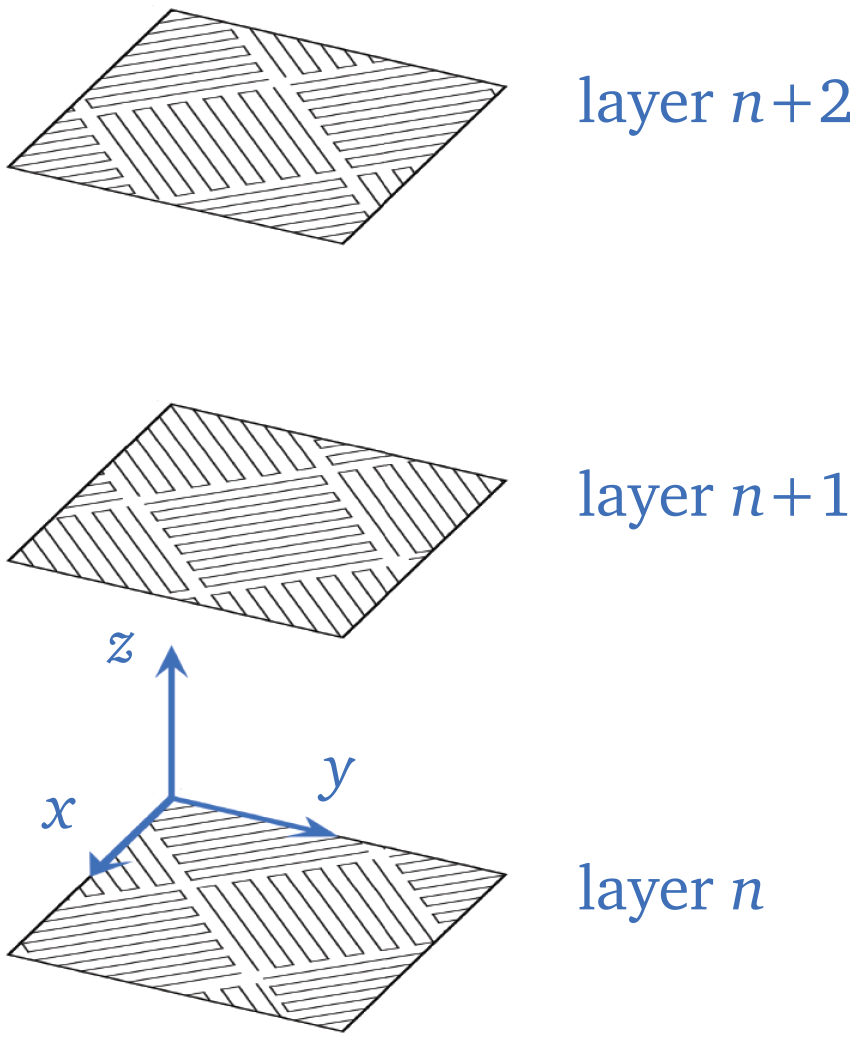
The applied build strategy for all specimens, showing the laser paths for three subsequent layers. The island pattern makes up the bulk of the part, and thereafter a contour path completes the outer surface layer. The layer thickness is 30 µm in this study.
Three different renditions of SLM manufactured grade 300 (1.2709) maraging steel specimens were produced. These are monolithic 100 mm × 100 mm plates of 5 and 10 mm thickness, and a profile plate with the same areal density as the 10 mm thick plate (see Figure 2). Note that the geometry of these profile plates was not optimised. Post SLM, half of the specimens of each type underwent a 6 h heat treatment at 490 °C before cooling to room temperature in air. This heat treatment is the industry standard, and has shown to be the most reliable method for high tensile strength (Casati et al., 2016). It should be noted that around a quarter of the way through the fabrication process, the machine was stopped to replenish powder supplies. The pause during which the laser was not heating the specimens caused cooling of the already built material, and thus a small notch formed on the surface of each plate, hereafter referred to as the ‘print-stop line’.
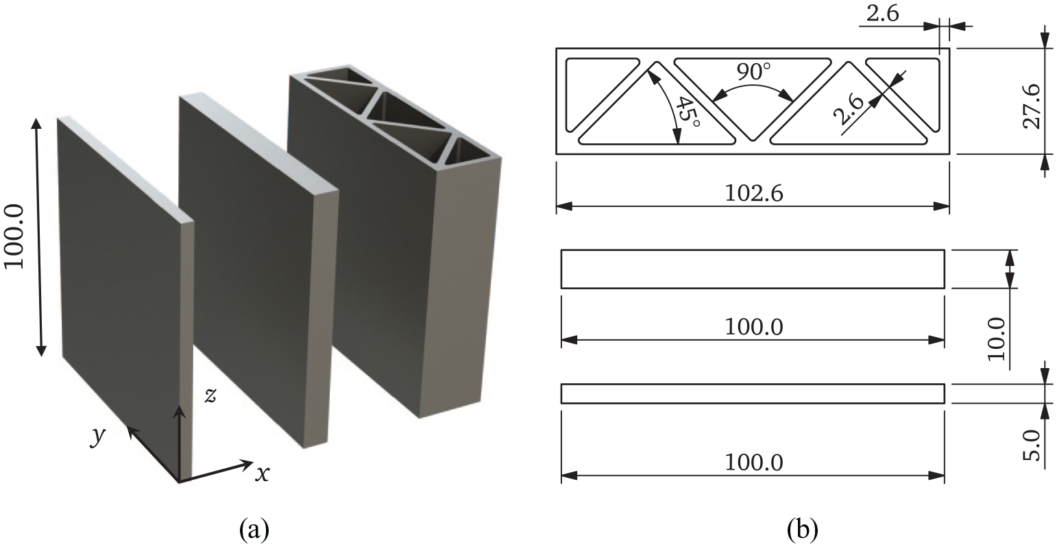
Geometry of AM maraging steel plates used in the ballistic impact tests, where: (a) shows a 3D render with the coordinate system and (b) the cross-sectional geometries of the plates (all linear dimensions in mm).
Metallurgical studies
The microstructure of both the as-built and the heat-treated materials was investigated with a Zeiss Ultra 55 Limited Edition Field Emission scanning electron microscope (SEM) and a Leica MEF4M optical microscope (OM). The samples were prepared by mechanical grinding and polishing to 1 µm, followed by either etching for 2 min in 2% Nital (Zipperian, 2010) or vibration polishing. For the latter, the samples were polished using a VibroMet2 from Buehler for 12 hours to remove the final deformation layer. The suspension used with the vibration polisher had pH 8 and contained SiO2 particles with a size of 0.02 μm. Finally, after the final polishing step, all samples were rinsed in an ultrasonic acetone bath for 5 minutes to obtain a clean surface finish. The etched samples were used for imaging in the SEM using secondary electron mode, while the vibration polished samples were used for OM imaging and electron backscatter diffraction (EBSD).
Figure 3 shows a comparison between as-built samples (shown on the left) and the heat-treated samples (shown on the right) of the maraging steel in all directions. The build direction was defined as PD (or
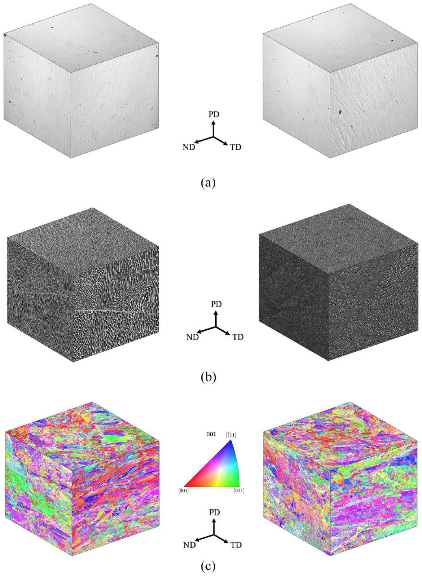
Cubes illustrating the microstructure of the as-built (left) and the heat-treated (right) AM maraging steel in different directions: (a) OM images of a polished sample, (b) SEM images of an etched sample and (c) inverse pole figure (IPF) maps acquired by EBSD where colours are indicative of grain orientation.
Material testing
The as-built and heat-treated materials were both tested in quasi-static uniaxial tension, while only the as-built material was tested at elevated strain rates for the reasons set out below. Tensile specimens with the dimensions given in Figure 4(a) were machined from a 5 mm thick AM maraging steel plate at 0°, 45° and 90° with respect to the build direction (see Figure 4(b)) using spark erosion and a lathe. No tests were carried out in the thickness direction. However, an example of such experiments can be found in Forrestal et al. (2014). The diametres of the gauge area of each specimen were measured before testing with a precision caliper and were found to be within 0.02 mm of the nominal 3 mm. An overview of the material and component tests is sketched in Figure 5.
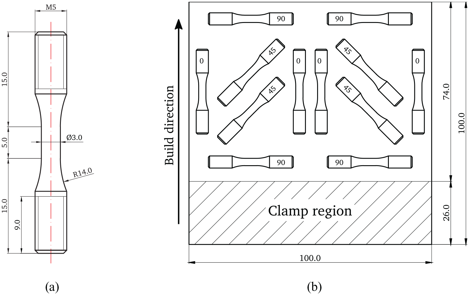
(a) Specimen geometry and (b) extraction scheme from a 5 mm thick plate at 0°, 45° and 90° with respect to the build direction (linear dimensions in mm).
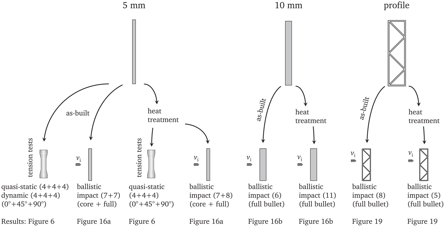
Overview of experimental programme, where the number in parenthesis indicate the number of tests for each case. All tension test specimens were machined from the 5 mm plates, and all plates from Figure 2 were subjected to ballistic impact.
Quasi-static tests were conducted at room temperature using an Instron 5982 universal testing machine at 0.3 mm/min, leading to an initial strain rate of
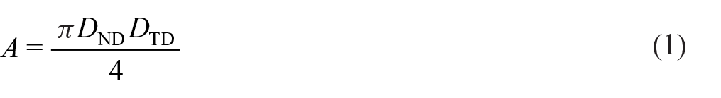
where
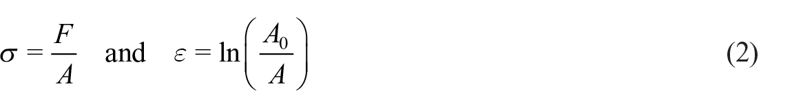
where
Key results from quasi-static tensile tests.
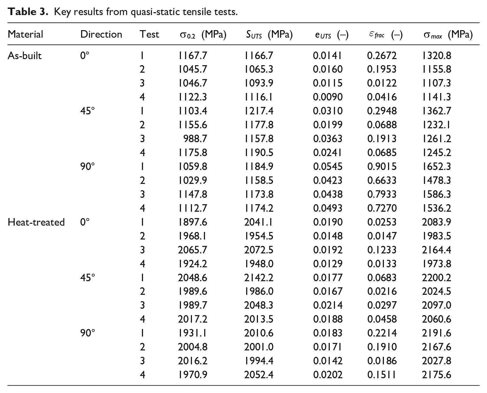
Figure 6(a) shows the quasi-static true stress-strain curves of the as-built and heat-treated material in the three tested directions, with four repetitions in each direction. On the one hand, and in spite of a considerable scatter in the results, it can be clearly observed that after heat treatment the initial yield stress of the material is almost doubled, reaching values above 2 GPa. On the other hand, the ductility of the heat-treated material was significantly reduced compared with that of the as-built samples, especially in the 90° direction.
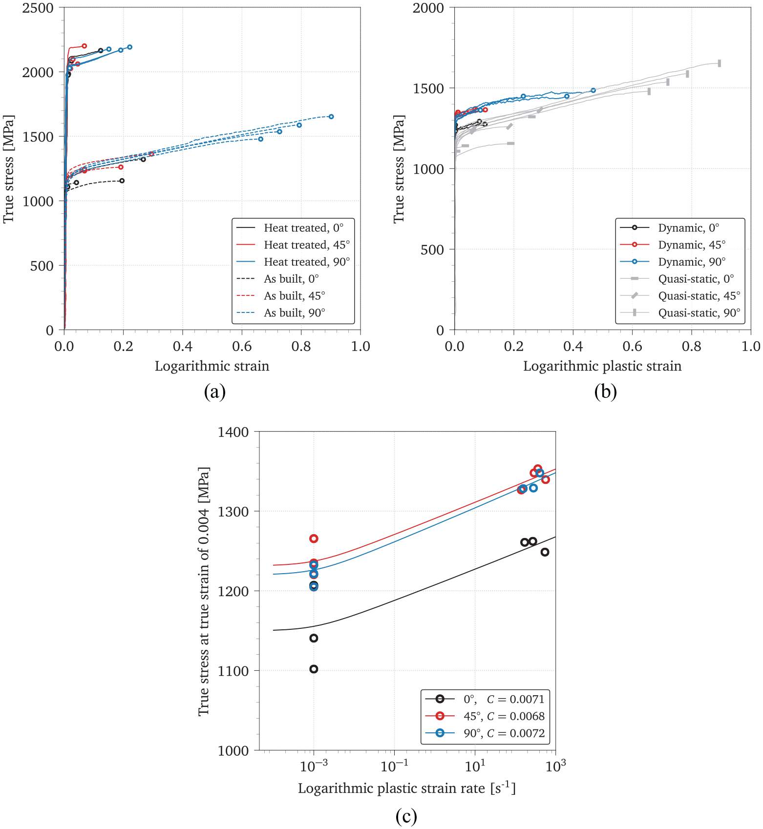
Results from quasi-static and dynamic tensile tests on AM maraging steel specimens: (a) true stress-logarithmic strain curves from quasi-static tensile tests, (b) true stress-logarithmic plastic strain curves from SHTB tests of as-built specimens only (compared with the corresponding quasi-static curves in grey) and (c) true stress-logarithmic plastic strain rate curves from quasi-static and SHTB tests at a true plastic strain of 0.04.
Whilst the scatter made it difficult to extract robust conclusions, it appeared that the initial yield stress of the as-built material was not isotropic. Indeed, tests in the build direction seemed to yield earlier than those in the 45° or 90° directions, although the results were also more dispersed. The anisotropy in the failure strain was clearer, and the material showed a much higher ductility in the orientation orthogonal to the build direction than in the other two tested directions. In line with these results, tensile specimens in the 90° direction exhibited noticeable necking before failure. This is illustrated in Figure 7, where the most brittle (0°) and most ductile (90°) specimens are shown immediately before fracture occurred in the quasi-static tensile tests.
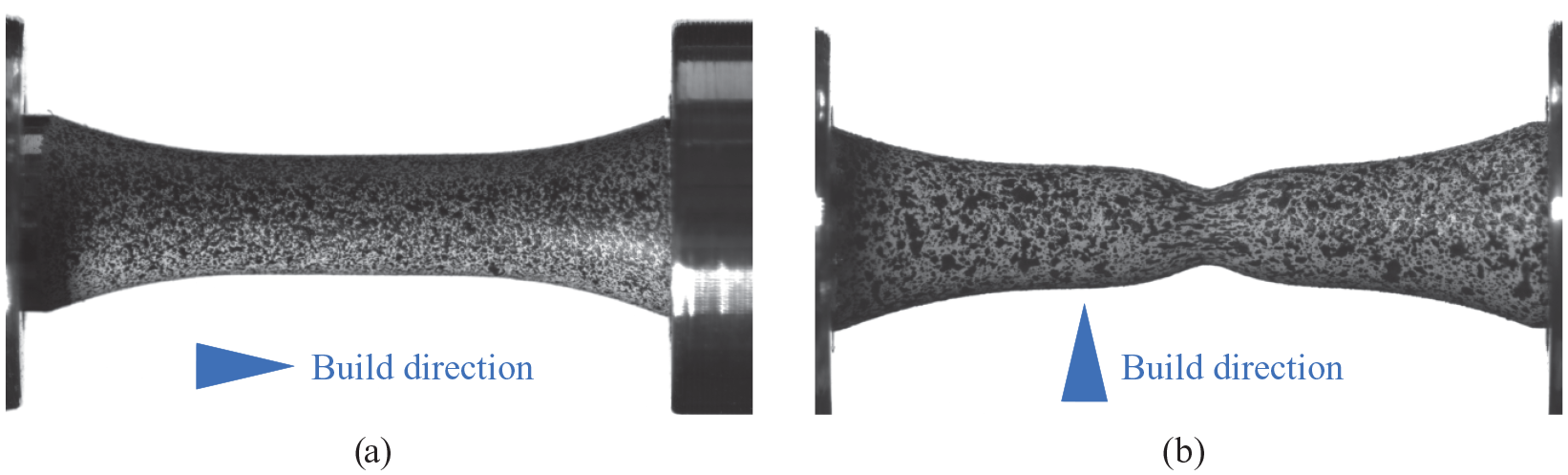
Images of: (a) the most brittle and (b) the most ductile specimens immediately before fracture in the quasi-static tensile tests. These specimens were extracted at 0° and 90° with respect to the built direction, respectively.
Ductility was significantly reduced after heat treatment. Some heat-treated specimens developed only marginal plastic strains before failure regardless of their orientation. The most considerable reduction was observed in the specimens orthogonal to the build direction, where strains at failure dropped from 0.77 to 0.15.
SEM fractographies of the tensile specimens supported the assessment of the difference in ductility of the as-built and heat-treated samples. Figure 8(a) shows a typical as-built 0° sample with numerous voids spread across the fracture surface, which reduce the ductility. Conversely, the as-built 90° sample in Figure 8(b) had mostly a dimpled fracture surface, with some large voids from particles and cracks. Such a dimpled fracture surface indicates ductile fracture. Fractographs of the heat-treated samples showed signs of quasi-brittle, cleavage-type fracture that were not present in the as-built specimens. From the fracture surfaces of the heat-treated samples in Figure 8(c) and (d) little difference was seen between the orientations, and both surfaces showed dimples in the centre of the specimens, albeit less than in Figure 8(b).
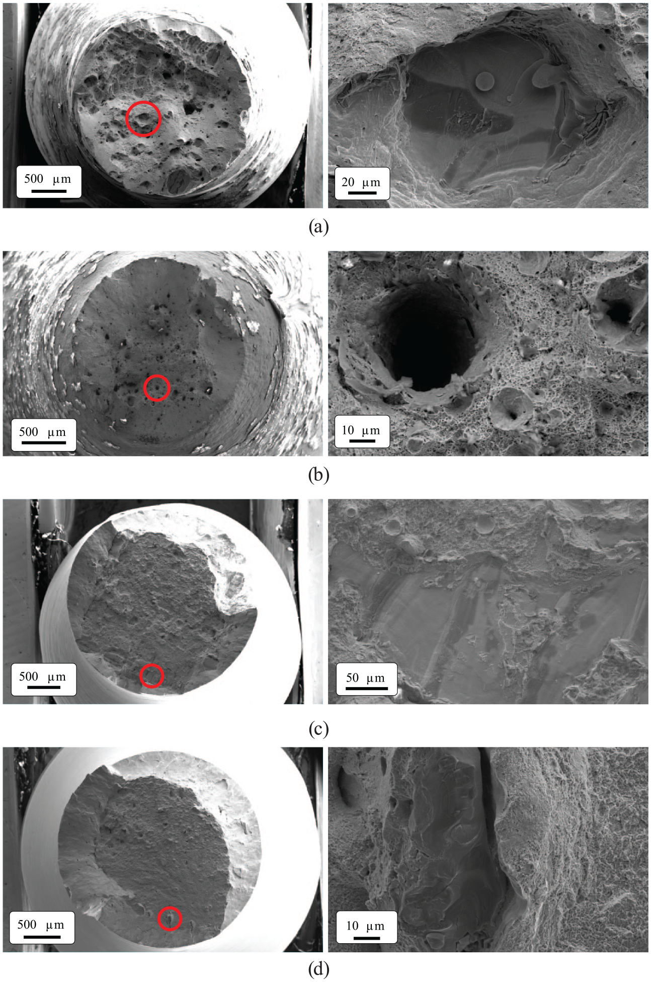
SEM images of fracture surfaces from quasi-static tensile tests: (a and b) show as-built 0° and 90°, respectively, while (c and d) show heat-treated 0° and 90°, respectively. The images on the right show a close up of the area marked with a red circle on the left image.
Dynamic split-Hopkinson tension bar (SHTB) tests were conducted to characterise the material at elevated strain rates. Since the strain rate sensitivity is known to be low in ultra high-strength steels (Børvik et al., 2009), these tests were conducted on the as-built material exclusively. Seventeen specimens were tested with four successful tests for each of the directions 0°, 45° and 90° at strain rates ranging from 140 to 670
The true stresses corresponding to a true plastic strain of 0.04 are plotted in Figure 6(c) for the quasi-static and dynamic tests, where the positive strain-rate sensitivity of the material can be clearly observed. The lines in the figure correspond to a best fit to a viscoplastic term in the form
where
The resulting fracture surfaces from the dynamic tests are shown in Figure 9 for a representative sample at 0° and 90°. As seen from the curves in Figure 6(b), the samples at 90° were consistently more ductile also at high strain rates. This difference is illustrated by the fracture surfaces, which show that the 0° sample (Figure 9(a)) contained many more larger voids and defects compared with the 90° sample (Figure 9(b)). This was also consistent with what is shown in Figure 8.
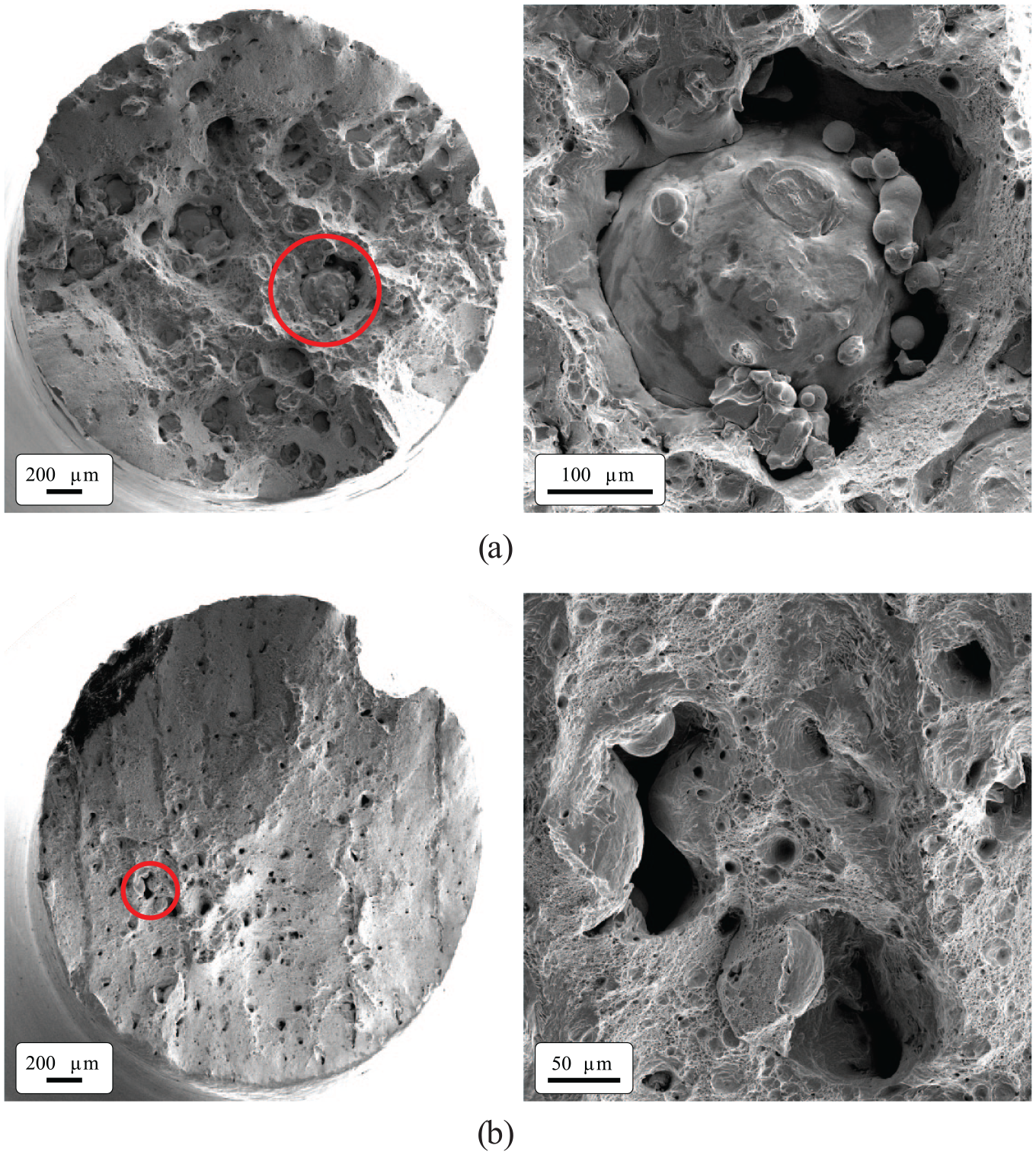
SEM images of the fracture surfaces from typical dynamic tensile tests on as-built specimens: (a) 0° and (b) 90°. The images on the right show a close up of the area marked with a red circle on the left image.
The large particle decorated with a number of unmolten maraging steel powder particles shown in Figure 9(a) deserved more attention, mostly because particles of this size can be detrimental for the ductility of any metallic material. The diametre of the particle was approximately 300 µm, that is, roughly 10 times bigger than the powder particles used in the print. Thus, it was too large to be a part of the powder used and may be a result of micro-segregation (Gorsse et al., 2017; Kim et al., 2020). This problem may be due to an unusually high percentage of titanium and oxygen in some powder particles, which results in the rapid flow of titanium to the front of the melt pool during fabrication, leaving disproportionate concentrations of that element. Even with a very low concentration of oxygen, oxidation can occur and leave brittle regions in the material that can lead to cracking. The chemical composition of these large particles and the base material were analysed under energy-dispersive X-ray spectroscopy (EDS) to support this argument. The results of the analyses plotted in Figure 10 clearly confirmed the high concentration of titanium and oxygen in the large particles compared to the base material.
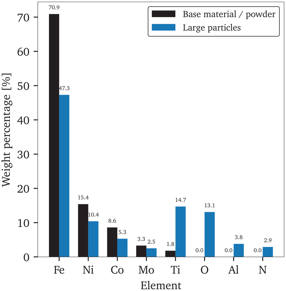
Comparison of the chemical composition of the base material and the large particles found in the material, obtained by EDS.
To better understand the influence of the heat treatment on this large particle, one tensile test specimen was investigated in a Nikon XT H225 ST MicroCT machine. First, the as-built specimen was scanned and the locations of some of the larger particles in the gauge area were determined. Thereafter, the same specimen was heat-treated for 6 h at 490 °C, before it was re-scanned. Figure 11 shows the same specimen’s cross section at the largest obtained particle both before and after heat treatment. As seen, these larger particles were unaffected by the heat treatment, and it can be concluded that the detrimental effect of the heat treatment on the ductility was not caused by growth of the larger particles.
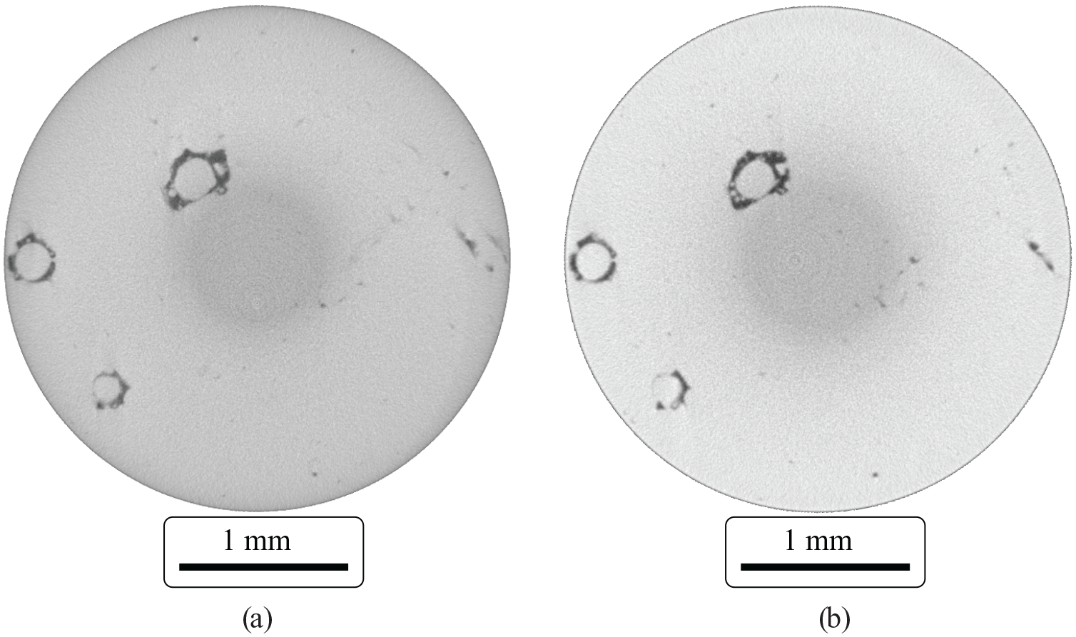
CT scans from the gauge area of a tensile test specimen: (a) as-built and (b) after heat treatment.
Ballistic tests
Experimental set-up
The impact tests on the maraging steel plates were carried out in a ballistic range described in previous studies (Børvik et al., 1999, 2009; Kristoffersen et al., 2020). For this study, a smooth-bored Mauser gun with a barrel length of 1 m was used. The gun was enclosed within a sealed 16
APM2 bullet used in tests (dimensions in mm).
One edge of each plate was fastened with a steel clamp extending 26 mm from the edge as shown in Figure 4(b), leaving the remaining three edges unrestrained. The plates were aligned so that the bullet impacted the target with a 25 mm vertical distance between each shot, allowing sufficient clearance for each test to be unaffected by preceding attempts, which allowed for a maximum of six shots in each 100 mm × 100 mm plate. However, due to frequent fragmentation and cracking of the material during impact, the number of tests in each plate were determined on a case-by-case basis.
The plates were weighed prior to testing and densities of 8034.4 and 8027.2 kg/m3 were recorded for the as-built and the heat-treated materials, respectively. Measuring the plate thickness with a precision caliper found agreement with the nominal value of 5 mm to within 0.1 mm.
Results
Monolithic plates
Figure 13 shows representative time-lapses of the ballistic tests of as-built and heat-treated monolithic plates with thicknesses of 5 and 10 mm impacted by APM2 bullets. The initial and residual velocities, respectively
Ballistic limit velocities for each target tested as predicted by the Recht-Ipson model, in metres per second.
Timelapse of ballistic impacts of as-built and heat-treated monolithic plates with thicknesses of 5 and 10 mm. The projectile is the APM2 bullet in all cases: (a) 5 mm, as-built plate,
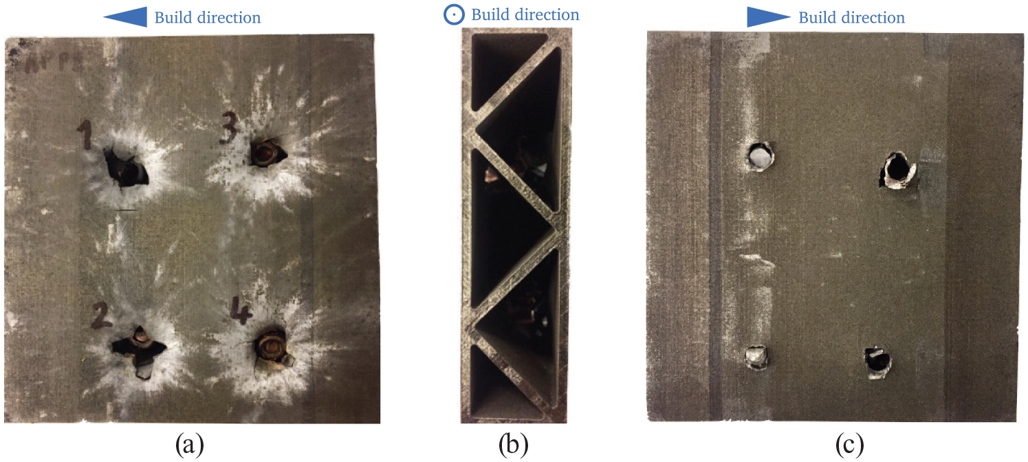
Photographs of 10 mm thick as-built and heat-treated plates after testing are shown in Figures 14 and 15, respectively. The first notable difference between these was the seemingly higher ductility of the as-built plate compared with the heat-treated one. The perforation of the as-built plate in Figure 14 resembled ductile hole growth with tendencies to petalling on the exit side. The deformed and perforated zone was localised and there was no cracking, therefore these plates were suitably reusable for multiple tests. This was not the case for the heat-treated plates, which were much more prone to cracking as illustrated by the pictures in Figure 15(a) and (b). Here, the first impact (1) at
Photos of as-built 10 mm maraging steel plate after three tests at (1) 919.7 m/s, (2) 705.3 m/s and (3) 829.8 m/s: (a) front (bullet entrance) of the plate with a part of the bullet stuck in place and (b) back (bullet exit) of the plate.
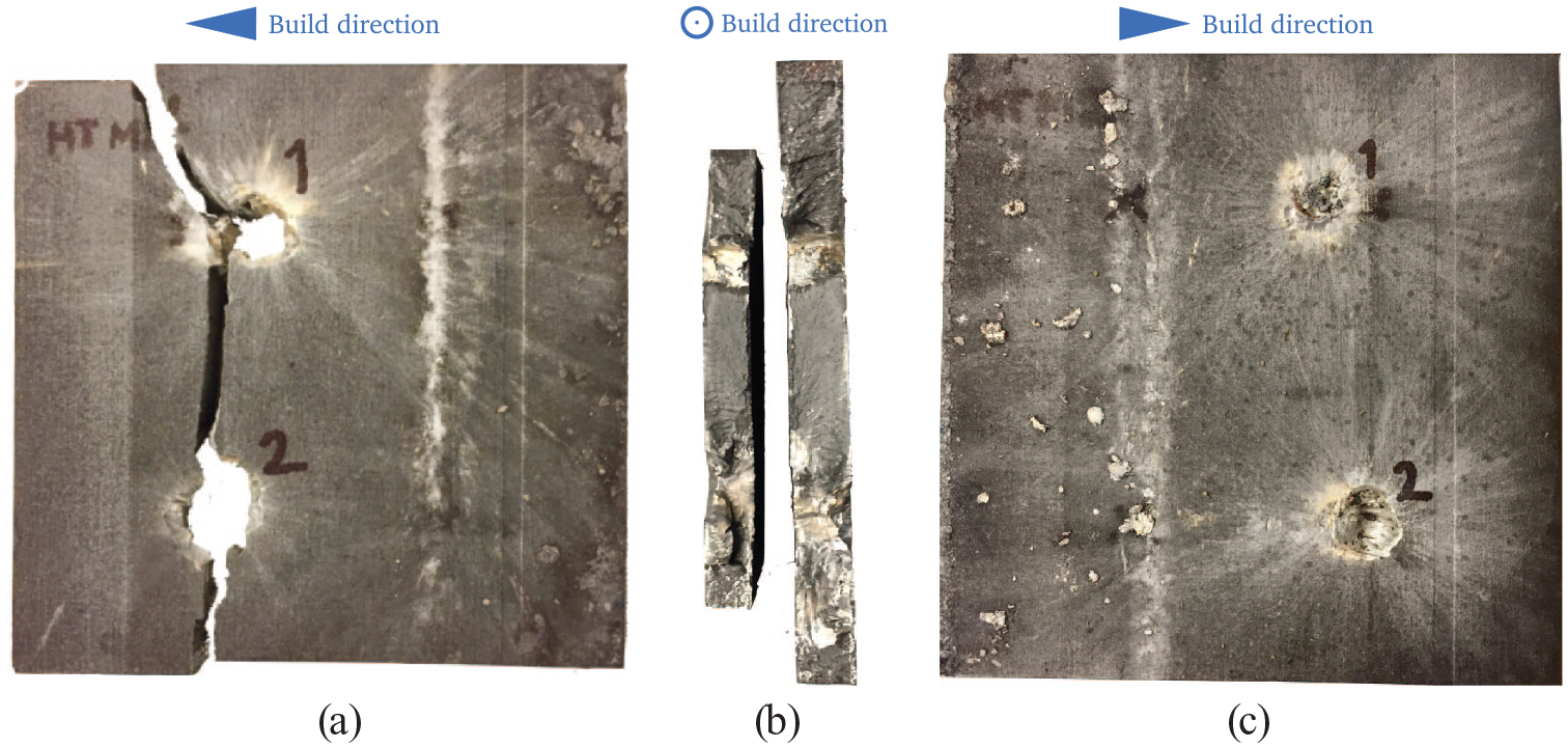
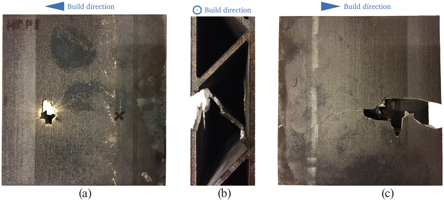
Photos of the heat-treated 10 mm maraging steel plates after shooting: (a) shows the plate fragmenting in two after tests at (1) 932.9 m/s and (2) 822.9 m/s and (b) surface of the fracture area and (c) shows bullets not able to perforate the plate at (1) 511.0 m/s and (2) 626.9 m/s.
The fracture surface in Figure 15(a) was clearly normal to the print direction (hereafter referred to as ‘print-line’), which according to the material tests had by far the lowest ductility (see Figure 6). The observation that cracks and breakages occurred along certain print-lines in the plate depending on where the bullet struck is sufficient evidence to disregard the ‘print-stop line’ described in Section 2.2 as a cause for this effect. In the most extreme cases, the plate fully fractured and broke in two along the print-line as shown in Figure 15(a) where the plate was clamped along the print-line, allowing a large fragment (almost half the plate) to break away. This result sometimes occurred even without perforation. Thus, when a plate produced by SLM is loaded in all directions, fracture is expected to occur in the direction with the lowest ductility, that is primarily along the print-line. Fracture of this nature likely contributed to the large scatter observed in the residual velocities.
Initial and residual bullet velocities

where
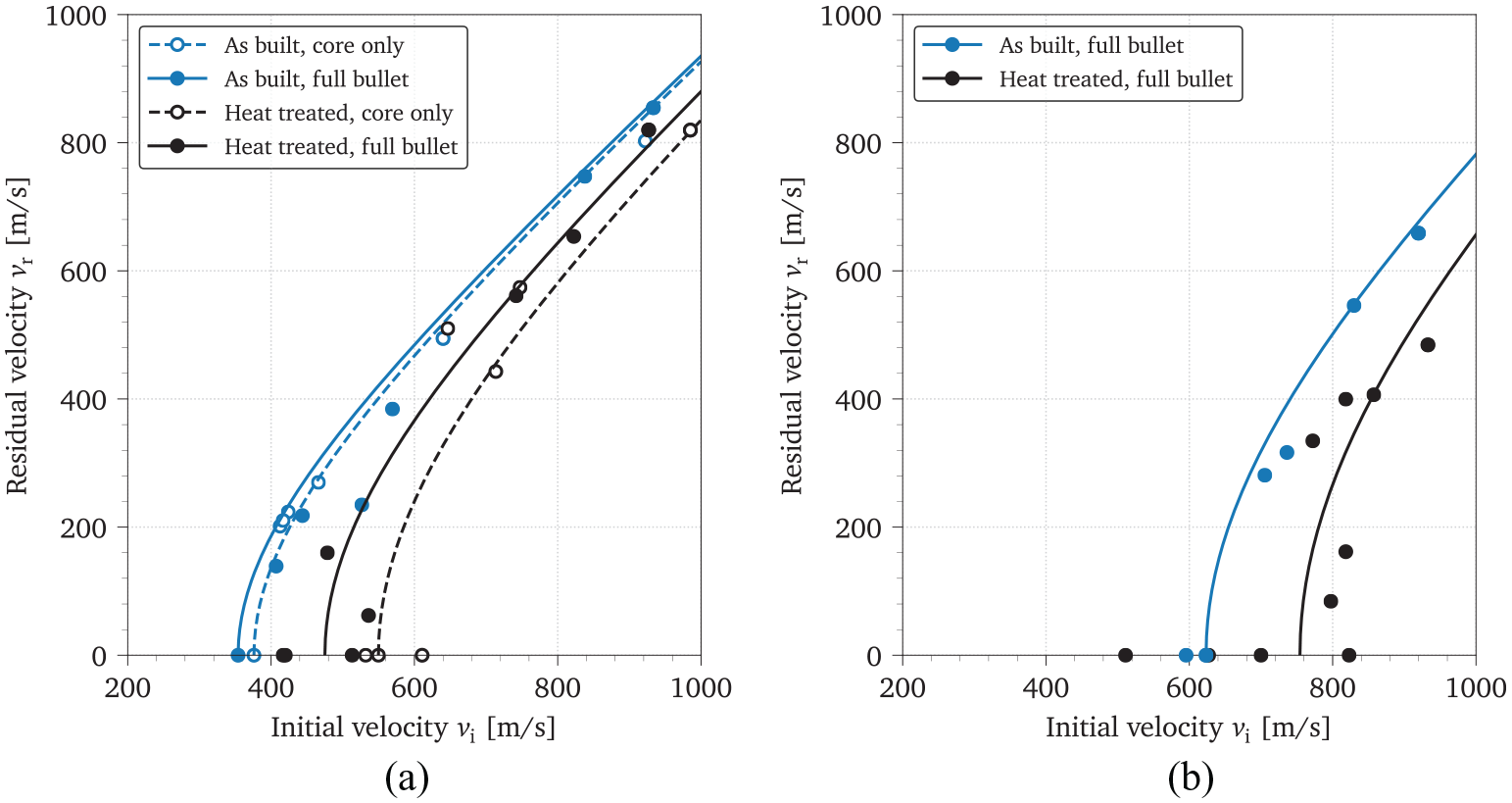
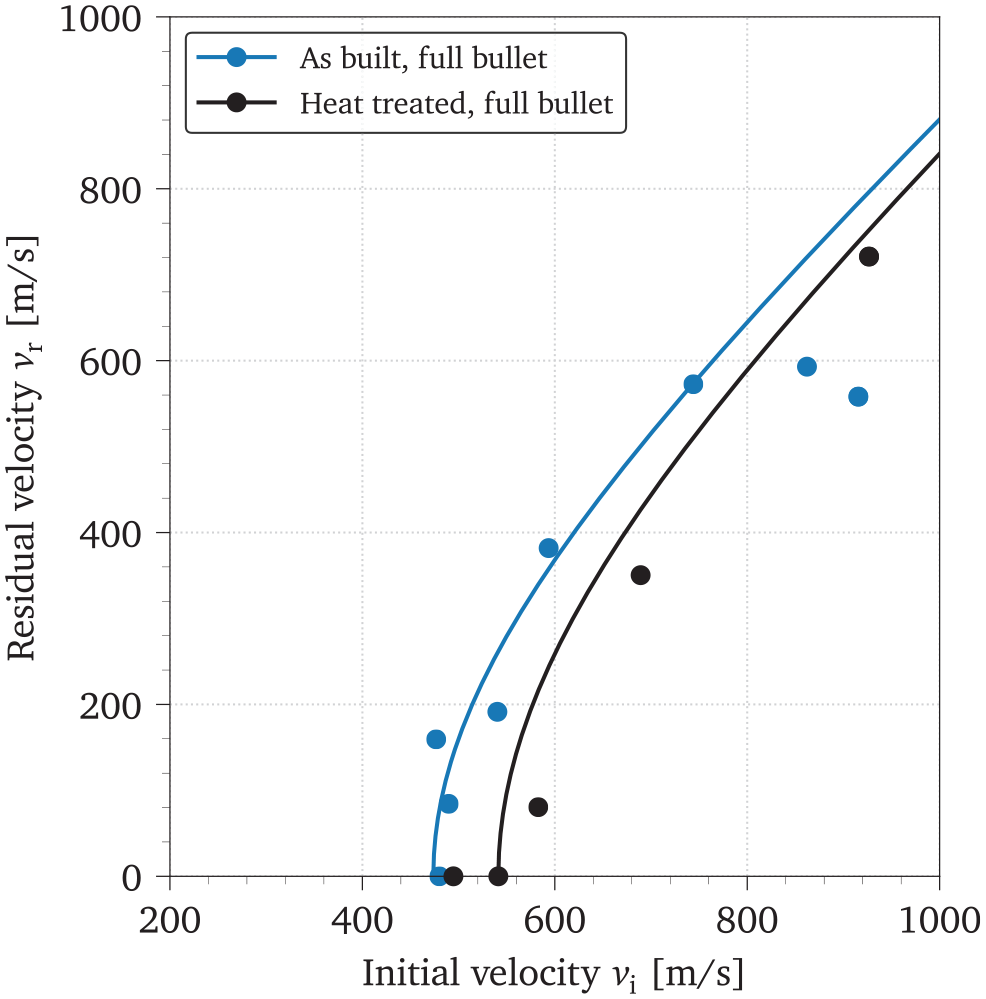
Ballistic limit curves of the monolithic plates: (a) 5 mm plates and (b) 10 mm plates.
Figure 17 shows typical fracture surfaces inside the penetration channel of the as-built and heat-treated samples for the 5 mm monolithic plate. The top right close up image of the as-built sample in Figure 17(a) shows a crack in the fracture surface. This crack was parallel to the direction of the perforation, and small spherical particles – assumed to be residual unmolten powder from the SLM fabrication – can be observed at the bottom of the crack. Conversely, for the heat-treated sample the surface is smoother and no particles can be seen. It appears that fragments of the plate were torn off during penetration by the bullet, leaving a brittle fracture surface. This is shown in Figure 17(b), which also shows voids in the torn surface.
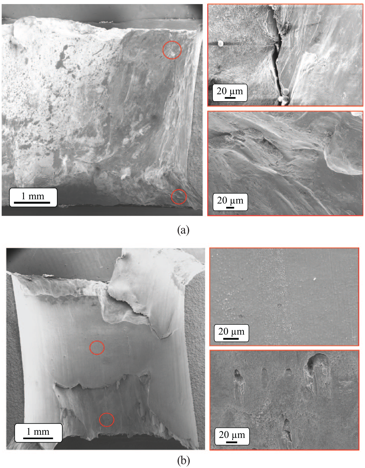
SEM images of the penetration channel in: (a) the as-built and (b) the heat-treated 5 mm monolithic plates (b), where the impact direction is from top to bottom. The images on the right show a close up of the area marked with a red circle on the left image.
Profile plates
The profile plate targets were clamped so that the front panel of the plates was orthogonal to the bullet entry direction, and the inner structure was visible to the high-speed camera. This alignment conforms with the clamping area indicated for the monolithic plates in Figure 4(b). All target profile plates were able to fracture the hard steel core of the APM2 bullet to some extent, as can be seen in the timelapse in Figure 18(a). Figure 18(b) shows the most destructive case, where the bullet shattered and the profile plate was severely damaged, all the while preventing perforation. Like for the monolithic plates, the as-built material displayed a more ductile response than the heat-treated material, with comparatively very little fragmentation. Even though the bullet hole in the as-built material showed limited indication of ductile hole growth and only mild signs of petalling can be seen in Figure 19, the perforation process appeared to be ductile.
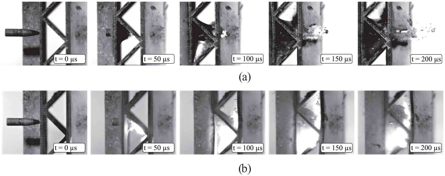
Profiles timelapse of ballistic tests: (a) as-built and (b) heat-treated.
Photos of the as-built profile plates after four tests at (1) 540.3 m/s, (2) 489.7 m/s, (3) 476.7 m/s and (4) 480.0 m/s: (a) front (bullet entrance) of the plate, (b) side of the plate and (c) back (bullet exit) of the plate.
The brittle nature of the heat-treated material became more evident for the profile plates. Figure 20 displays a heat-treated profile plate impacted at 926.6 m/s where there was significant damage to the inner corrugated structure and to the panel on the exit side – a crack running along the entire width of the specimen can be seen in Figure 20(c). The level of destruction rendered these plates unsuitable for additional tests, thereby limiting the number of data points compared to the as-built material.
Photos of the heat-treated profile plates after one test at 926.6 m/s: (a) front (bullet entrance) of the plate, (b) side of the plate and (c) back (bullet exit) of the plate.
The fit of the Recht-Ipson model to the experimental results is shown in Figure 21, with a considerable scatter of the results. Some of the tests were discounted from the fit due to the bullet impacting the plate in the corner of the profile rather than the centre, or the bullet exiting the same hole as a previous test. The resulting ballistic limit velocities for each profile are included in Table 4. The estimated ballistic limit of the profile plates was, as expected, between that of the two monolithic plates (Wadley et al., 2013).
Ballistic limit curves for the tested profiles with Recht-Ipson model parametres
Summary and discussion
While the utility of employing AM to create intricate geometries tailored to fill gaps in material property space has been made clear (Ashby, 2013), the material properties arising from the process are still under investigation. This applies to both as-built and heat-treated material. The anisotropy may range from small (Meneghetti et al., 2017) to considerable (Mooney et al., 2019) in as-built AM maraging steel. In this study a clear anisotropy was found in the material, to some extent for the yield stress
After heat treatment,
The ballistic impact tests showed that the heat treatment increased the ballistic limit velocity noticeably. For the 5 mm monolithic plates, the increase was approximately 25%. The as-built plates had clear signs of ductile hole growth and petalling in Figure 14, and the heat-treated plates either stopped and shattered the bullet or tended to fragment (illustrated in Figure 15), leaving a completely different fracture surface as depicted in Figure 17. Reflecting the tensile test results, the heat-treated plates showed more scatter than the as-built ones as plotted in Figure 16. This scatter makes it difficult to draw any robust conclusions regarding the difference between using the full APM2 bullet and the core only. Modifying the heat treatment for optimum perforation resistance is a natural possibility for further research.
Doubling the plate thickness to 10 mm predictably increased the ballistic limit velocity (see Table 4 and Figure 16); an increase of over 60% was achieved for both as-built and heat-treated plates. This result is quite interesting given that a 60% increase in velocity more than doubles the kinetic energy of the bullet. The as-built plates absorbed the energy by plastic deformation to a larger extent than the heat-treated plates, which showed a high degree of fragmentation. The effect of the heat treatment in terms of
Increasing the thickness of steel targets beyond 10 mm has been demonstrated to provide notable gains in terms of
A simple profile plate with the same areal density as the 10 mm plates was also built and tested. Using this truss-like structure rather than a monolithic 10 mm plate proved deleterious to the perforation resistance. Again the as-built plates were comparatively ductile. The APM2 bullet caused significant damage to the heat-treated plates, evident in Figure 20. Again the hard steel core of the bullet was broken despite the even lower thickness of the profile plates. The shattering of the steel core may be caused by extremely high magnitude stress waves arising upon impact against the extremely hard heat-treated plates with much higher yield stress. More complex geometries, like optimised gyroids, lidinoids or other advanced shapes, remain to be investigated.
Concluding remarks
The ballistic properties of a selective laser melting additive manufactured maraging high-strength steel were investigated. The material was tested in as-built and heat-treated configurations in the form of monolithic plates and truss-like profiles, and the following conclusions were drawn:
• After heat treatment at 490 °C for 6 h, the yield stress of the material was approximately doubled compared to that of the as-built material. Conversely, the ductility was drastically reduced.
• Ballistic testing of as-built and heat-treated plates showed the significant potential of this material for protective applications. The resistance of the samples was such that the high-strength steel core of the armour-piercing bullet shattered in many tests, in spite of the relatively low thickness of the target plates.
• Heat treatment increased the ballistic limit of the tested targets in all configurations. However, the heat-treated targets were more prone to cracking and fragmentation, and therefore did not withstand as many shots as the as-built plates, which displayed a more ductile behaviour. This is in agreement with the results of the tensile tests.
• A significant scatter was found in both the tensile and ballistic properties. Relatively large voids and particles were found in the additive manufactured maraging steel samples, which were most likely responsible for the scattered results. These large particles were investigated and it was shown that heat treatment did not alleviate the problem.
To conclude, this work demonstrated the potential of selective laser melting maraging steel in protective applications. However, we believe that there is room for improvement regarding the strength – ductility trade-off for this material, especially through minimising the presence of larger voids and particles. Moreover, the heat treatment could be optimised to find a balance between strength and ductility, and in turn significantly improve the ballistic performance of the material.
Footnotes
Acknowledgements
The authors would like to acknowledge Mr. Trond Auestad, Mr. Tore Andre Kristensen and Mr. Tore Wisth for assistance with the various experimental programmes, and Dr. Susanne Thomesen and Mr. Ole Tore Buset for the help with the microscopy and CT scanner.
Data availability
The raw/processed data required to reproduce these findings cannot be shared at this time as the data also forms part of an ongoing study.
Declaration of conflicting interests
The author(s) declared no potential conflicts of interest with respect to the research, authorship, and/or publication of this article.
Funding
The author(s) disclosed receipt of the following financial support for the research, authorship, and/or publication of this article: The present work has been carried out with financial support from Centre of Advanced Structural Analysis (CASA), Centre for Research-based Innovation, at the Norwegian University of Science and Technology (NTNU) and the Research Council of Norway through project no. 237885 (CASA). Ms. Maisie Edwards-Mowforth has worked under an Erasmus scholarship.