
Abstract
Objective:
This study aimed to identify latent conditions in a pediatric intensive care unit (PICU) by analyzing characteristics of flow disruptions (FD) during a simulation of a three-phased scenario.
Background:
The built environment of healthcare facilities contributes to FD that can lead to clinical errors and patient harm. In the facility design process, there is an opportunity to identify built environment features that cause FD and pose safety risks. Simulation-based evaluation of proposed designs may help in identifying and mitigating safety concerns before construction and occupancy.
Methodology:
During design development for a new 400-bed children’s hospital, a series of simulations were conducted using physical mock-ups in a large warehouse. A three-phased scenario, (1) admission and intubation, (2) cardiac arrest, and (3) bedside surgery involving a cannulation to extracorporeal membrane oxygenation, was conducted in a PICU room mock-up. Each scenario was video recorded from four angles. The videos were systematically coded to identify FD.
Results:
Analysis identified FDs in three ICU zones: respiratory therapists (RT) zone, nurse zone, and head of the patient. Challenges in these zones were related to spatial constraints in the RT zone and head of the bed, equipment positioning in the RT zone and nurse zone, and impeded visibility related to the location of the boom monitor in the nurse zone.
Conclusion:
Simulation-based evaluation of prototypes of patient care spaces can help identify characteristics of minor and major FD related to the built environment and can provide valuable information to inform the iterative design process.
Introduction
The intensive care unit (ICU) is a high-risk patient care environment. Avoidable and unavoidable adverse events frequently occur in this setting (Molina et al., 2018); these events occur due to several latent conditions, including high patient complexity, intensive equipment needs, the high number of caregivers, and challenges posed by the physical environment in which care is provided (Donchin & Seagull, 2002; Joseph et al., 2022). The ICU physical environment should support safe and high-quality care and not contribute to the complexity of care delivery. Therefore, features in the physical environment that creates barriers to safe care delivery should be carefully evaluated and addressed (Page, 2004). During the facility design process, there is an opportunity to proactively identify and mitigate potential safety risks in the ICU environment.
Flow disruptions (FD), defined as “deviations from the natural progression of a procedure that potentially compromise safety or efficiency” (Palmer et al., 2013; Wiegmann et al., 2007), are symptomatic of larger problems or latent conditions inherent in work systems such as ICU patient rooms that impact workflow and patient safety. Previous studies suggest that FDs directly impact the rate of medical errors in the surgical operating room (OR; Catchpole et al., 2006; Wheelock et al., 2015; Wiegmann et al., 2007, 2006). FDs could also lead to miscommunication, repeated tasks, procedural complications (Gillespie et al., 2012), impaired individual and team performance, and inferior evaluation (McMullan et al., 2021; Weigl et al., 2018; Wheelock et al., 2015; Wiegmann et al., 2007), poor patient outcomes (Tschan et al., 2015), and increased patient mortality (de Leval et al., 2000). A literature review synthesis on interruptions, distractions, and FDs suggested that an average of 20% of the operating time was spent on addressing FDs (Koch et al., 2020). Research has also demonstrated a direct relationship between the occurrence of minor FDs and major FDs in the OR (Joseph et al., 2019). Further, studies show that environmental factors, including room size, clutter, spatial layout and ineffective utilization of space, and inefficient equipment and storage placement, could contribute to FDs (Joseph et al., 2019; Joseph et al., 2021a; Joseph et al., 2021b; Taaffe et al., 2018, 2021). As a result, the staff develops workarounds to overcome these latent conditions in their environment, creating excess movement that contributes to additional FD (Joseph et al., 2019).
Research investigating FDs in the OR environment has provided an understanding of systems issues, efficiency, and quality outcome measures and has informed the OR design process (Blocker et al., 2012). Studying FDs has also been found helpful while conducting clinical simulations in physical mock-ups to identify latent conditions related to design. Clinical scenarios were simulated in an OR mock-up to analyze the behavior of clinical staff and to understand environmental and layout problems; this information was utilized to generate necessary design changes and recommendations (Shultz et al., 2020). Another study found similar patterns of FDs related to environmental hazards and layout between clinical simulations conducted in an OR physical mock-up and actual procedures in a live and fully functional OR (Joseph et al., 2021).
Studies suggest that an ergonomic assessment of the ICU environment through the science of human factors engineering could also be a promising approach to explore the equipment challenges in the ICU (Hardy, 2004); however, a human factors analysis is missing as it relates to the design of a supportive physical environment in the ICU. Studying FDs in other settings, such as ORs, reveals that this approach is helpful in identifying workflow challenges posed by the built environment as well as other system components such as equipment, tasks, and people; therefore, this method could be utilized in the ICU. However, ICUs are difficult to observe, and simulations offer a way to observe “work-as-done” (Hollnagel, 2017) without impacting patient privacy and staff workflow during critical procedures. Simulation-based evaluations of design prototypes represent the dynamic complexity of care delivery in high-risk settings. These simulations can help teams better demonstrate challenges posed by the built environment as compared to a traditional review of plans or even virtual or physical mock-up walkthroughs (Colman et al., 2019, 2020; Joseph et al., 2021c; Wingler et al., 2019). FD analysis of simulated scenarios can help teams identify latent conditions related to design prior to construction and occupancy.
Objective
A simulation-based evaluation was conducted as part of the design process for a proposed design of a pediatric intensive care unit (PICU) patient room. The objective of this study was to characterize FDs to the provider workflow and patient safety in the PICU by analyzing the simulation videos.
Method
Setting and Context
A three-phased scenario, (1) admission and intubation, (2) code and high-frequency oscillatory ventilation, and (3) planned extracorporeal membrane oxygenation (ECMO) cannulation, was conducted in a PICU room mock-up as a part of the design process for a new 400-bed children’s hospital. This simulation was conducted as a part of 86 scenarios tested in a 20-day period utilizing a team of clinicians who worked together in the current hospital ICU (Colman et al., 2020). Frontline nurses, respiratory therapists (RT), attending physicians, and ECMO personnel participated in simulations and contributed to testing different procedures in the mock-up setting. Each scenario was completed once. Table 1 represents the three scenarios representing the continuum of patient decompensation involving staff, equipment, and zones. Figures 1 and 2 represent two points in Scenarios 1 and 2.
Description of Tasks, Staff, Equipment, and Zones in Scenarios.
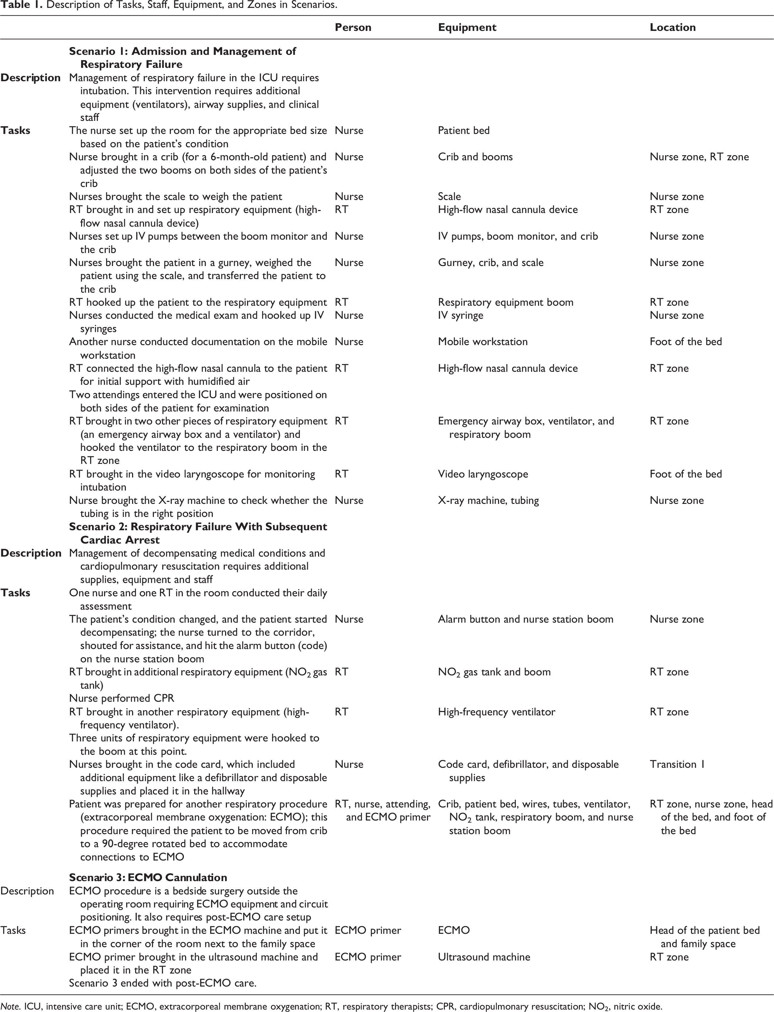
Note. ICU, intensive care unit; ECMO, extracorporeal membrane oxygenation; RT, respiratory therapists; CPR, cardiopulmonary resuscitation; NO2, nitric oxide.
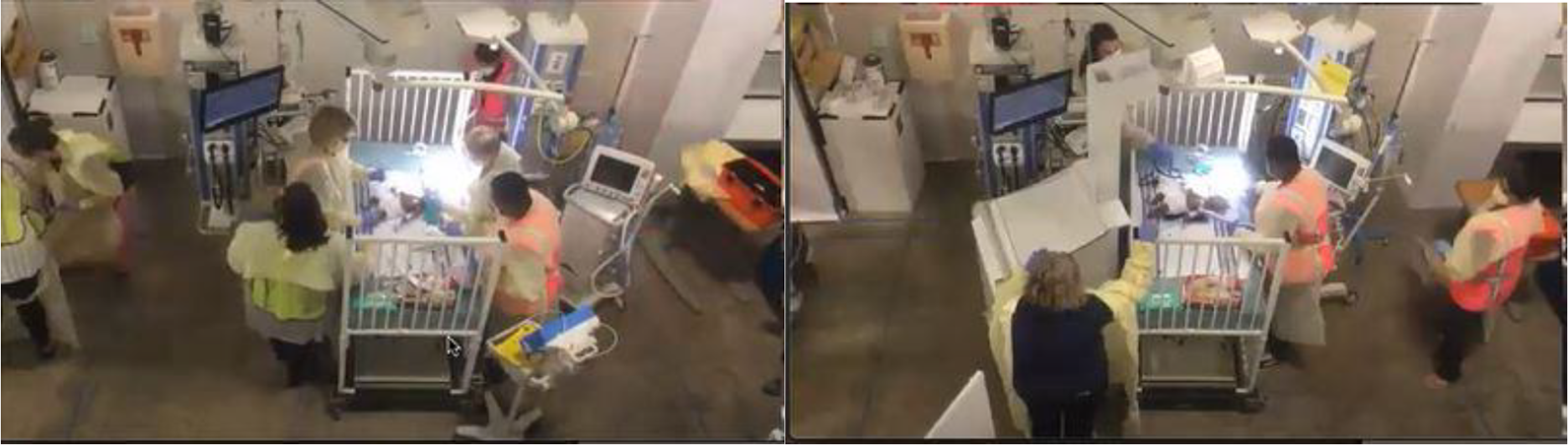
Mid-procedure in Scenario 1 (left), end of Scenario 1 (right).
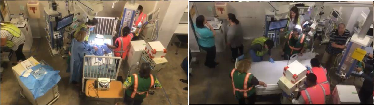
Mid-procedure in Scenario 2 (left), end of Scenario 2 (right).
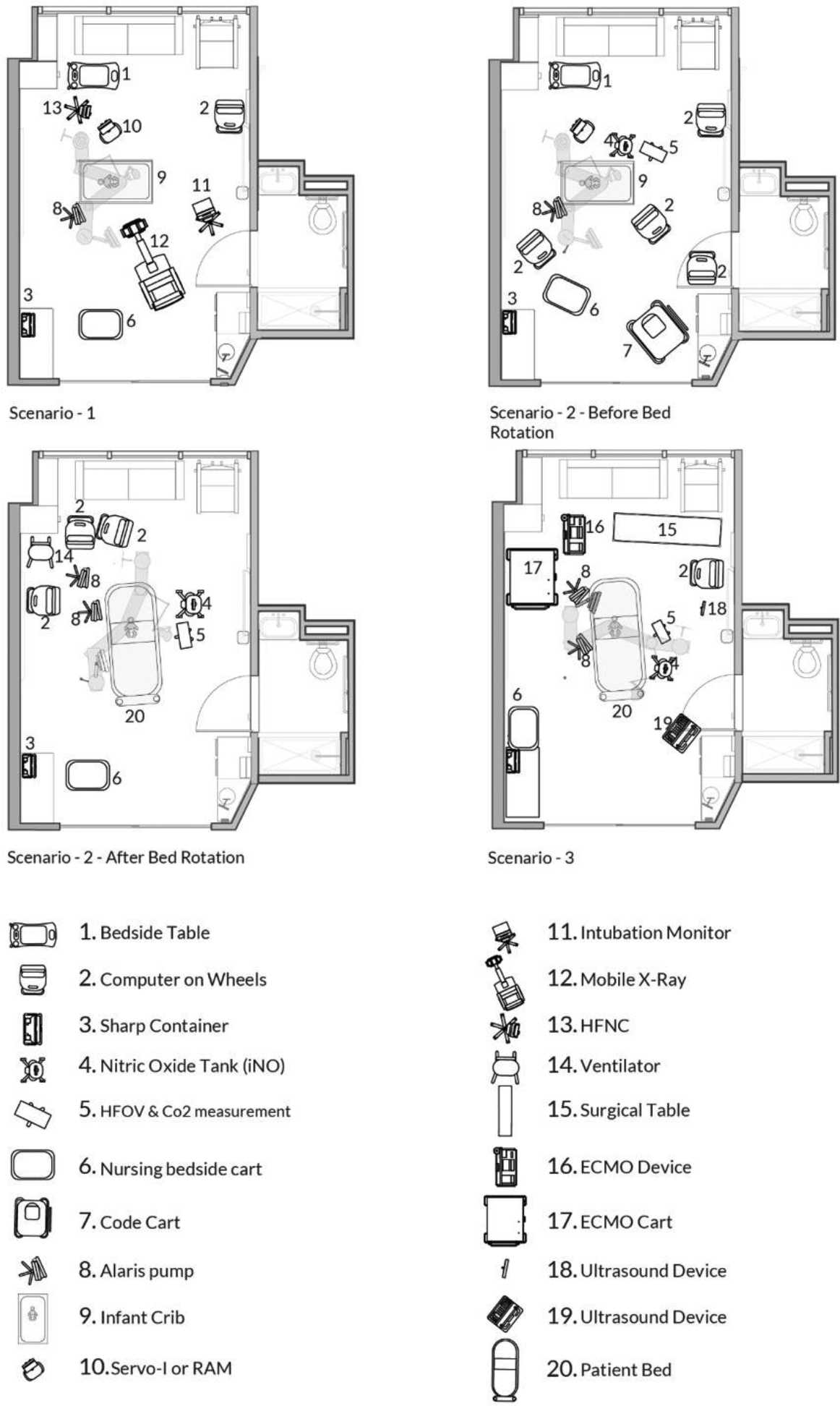
The full-scale mock-up representing the proposed PICU was constructed from cardboard and was part of a 100’000+ ft2 cardboard city representing the schematic design of inpatient bed units (Colman et al., 2020). The ICU room layout, including the bed positioning, is shown in Figure 3. The PICU mock-up included a combination of real equipment (e.g., bed, crib, nurse workstation, monitors, video laryngoscopy machine, booms) and a cardboard model of other equipment (X-ray, nitric oxide tank, ventilators, etc.). The boom was donated for simulation; respiratory equipment requiring medical gas and electrical outlets for infusion pumps were attached to the boom. Baskets were attached to hold emergency equipment such as suction tubing, bag/mask, and airway adjuncts. Design features were determined by a collaborative team of architects and clinicians to ensure that important features for clinical care and the architect team were demonstrated correctly in the mock-up. A low-fidelity mannequin was used as an infant patient. The study proposal was considered to be nonhuman subjects by the institutional review board.
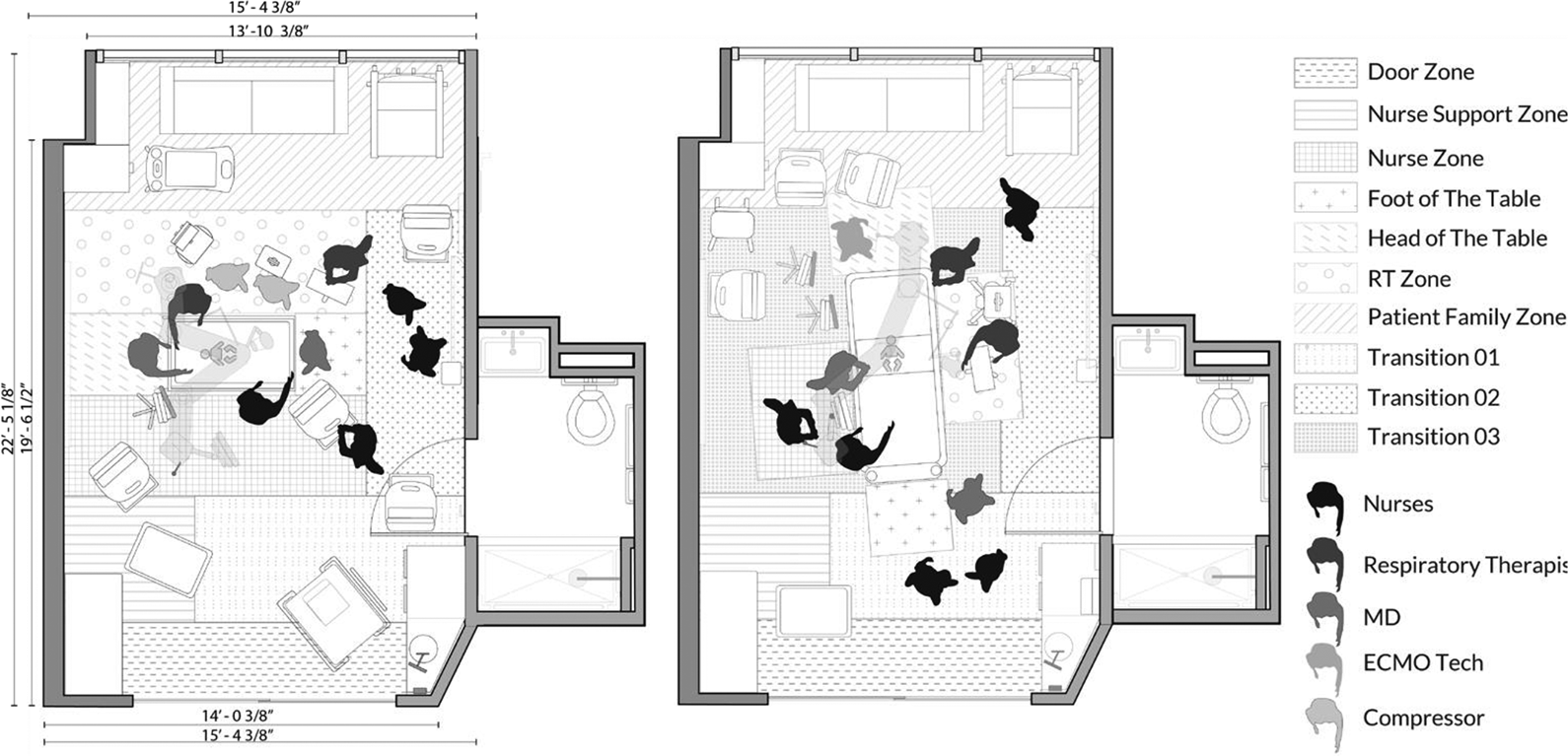
Intensive care unit zones identified for coding, left (patient in crib, before bed rotation), right (patient transferred, bed rotation).
Process
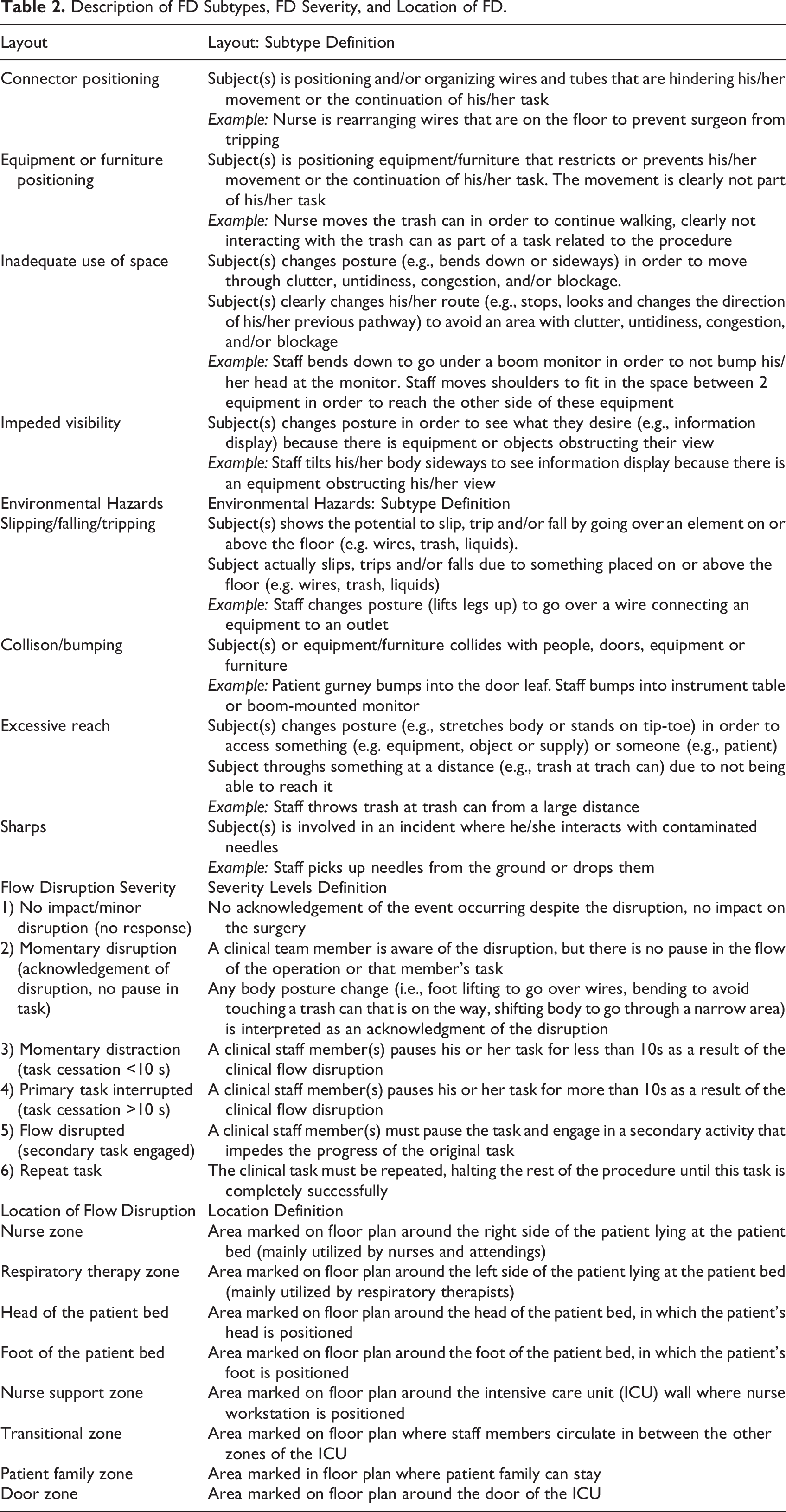
The three simulated patient care scenarios in the physical mock-up of the PICU were simultaneously video recorded from four corners of the room. The four viewing angles were combined into one screen playing all videos at once for coding and analysis. A detailed 3-h qualitative interview was conducted with a clinician while reviewing the events and processes in the recordings. During the interview, the expert clinician explained the events happening in the PICU mock-up. The clinician addressed the information regarding people, equipment, and procedures. The clinician also responded to questions to assist the coder understand the specifics related to the PICU events. The videos were then analyzed for FD using an adapted taxonomy for FD originally developed for evaluating disruptions in the OR (Palmer et al., 2013). Each observed FD was coded for the type of FD (only FDs related to layout and environmental hazard were coded as part of this study), subtype of FD, the severity of FD, location of FD, equipment involved in FD, staff type, and staff numbers involved in the FD in each of the three scenarios. Definitions for the analyzed FD components are shown in Table 2.
Prior to coding, a zoning map was created based on a walkthrough of the videos with a clinical expert, which clarified the work of different team members and how different PICU zones were utilized by teams of nurses, RT, attending physicians, family members, and other team members. Functional zones emerged from the discussion with the clinical expert and included the nurse zone, RT zone, head of the patient bed, foot of the patient bed, nurse support zone, transitions zones, family zone, and door zone (Table 2). These zones were utilized to mark the location of observed FDs. The location of the zones on the plan (head, foot, nurse zone, and respiratory therapy zone) depended on the bed orientation and changed if the bed was rotated. The location of the door zone, nurse support zone, and patient family zone remained fixed during different bed rotations.
Description of FD Subtypes, FD Severity, and Location of FD.
Analysis
The video recordings of the three scenarios were coded using a previously built coding template in Excel to identify the location (ICU zones) of FD as well as FD type, FD subtype, FD severity, equipment involved, staff type, and the number of staff involved in the disruption event. Descriptive statistics were generated to calculate the percentage of FDs occurring in each zone, types of FD, equipment involved, and severity of FD in each zone.
Results
The length of scenarios varied between 19 and 30 min. The number of disruptions observed and the rate of disruptions per minute were similar in Scenarios 1 (1.36) and 2 (1.5). Scenario 3 had fewer disruptions/minute (0.33). All team members, including RT, attending physicians, nurses, and ECMO personnel, were involved in disruptions in these three scenarios. The RT zone was associated with the highest number of disruptions (n = 40), followed by the nurse zone (n = 23). Disruptions were also observed at the head of the patient bed (n = 8), foot of the patient bed (n = 4), nurse support zone (n = 4), and transition zone (n = 2). Table 3 demonstrates FD type, severity, count, and percentage during different procedures in PICU zones.
FD Type, Severity, Count, and Percentage During Different Procedures in PICU Zones.
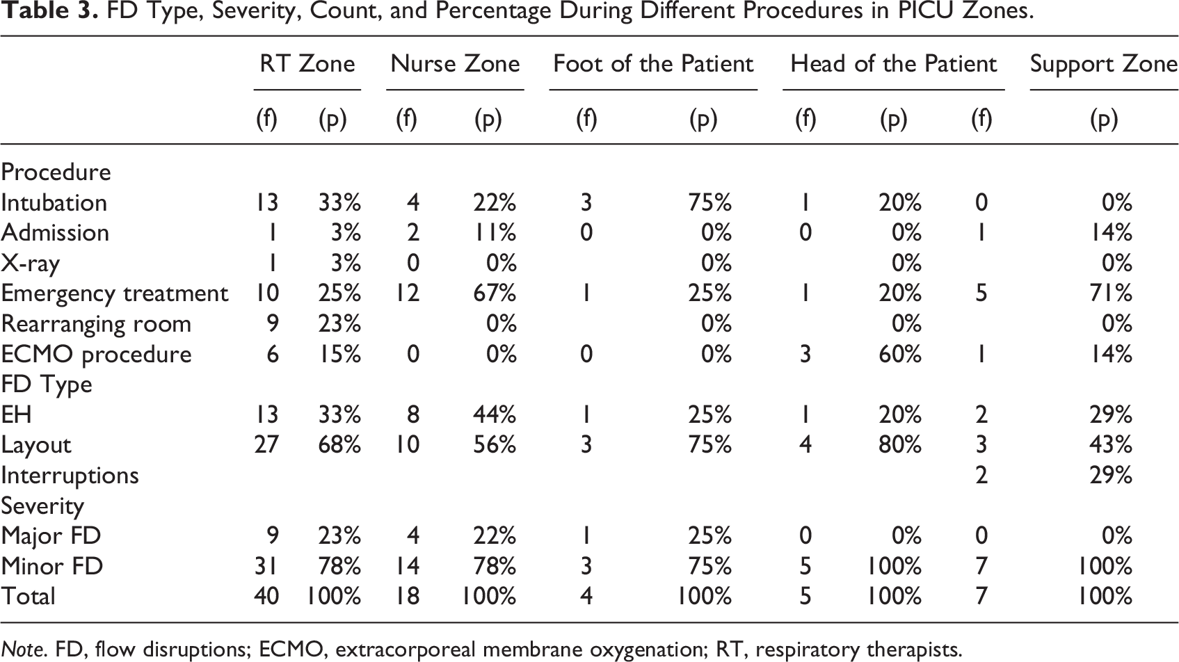
Note. FD, flow disruptions; ECMO, extracorporeal membrane oxygenation; RT, respiratory therapists.
RT Zone
FD characteristics
Equipment or furniture positioning, collision-bumping, and excessive reach were the majority (83%) of subtype disruption events experienced by the RTs in the RT zone. These events occurred in the RT zone mainly due to a lack of space for the additional and larger equipment used by the RTs, higher traffic of staff for complex events, and the location of the electrical outlets on the boom. Although the majority of the disruption events observed in the RT zone were minor disruptions (78%), the repositioning equipment while transferring the patient from the crib to bed led to major disruptions.
Equipment, spatial constraints, and clinical context
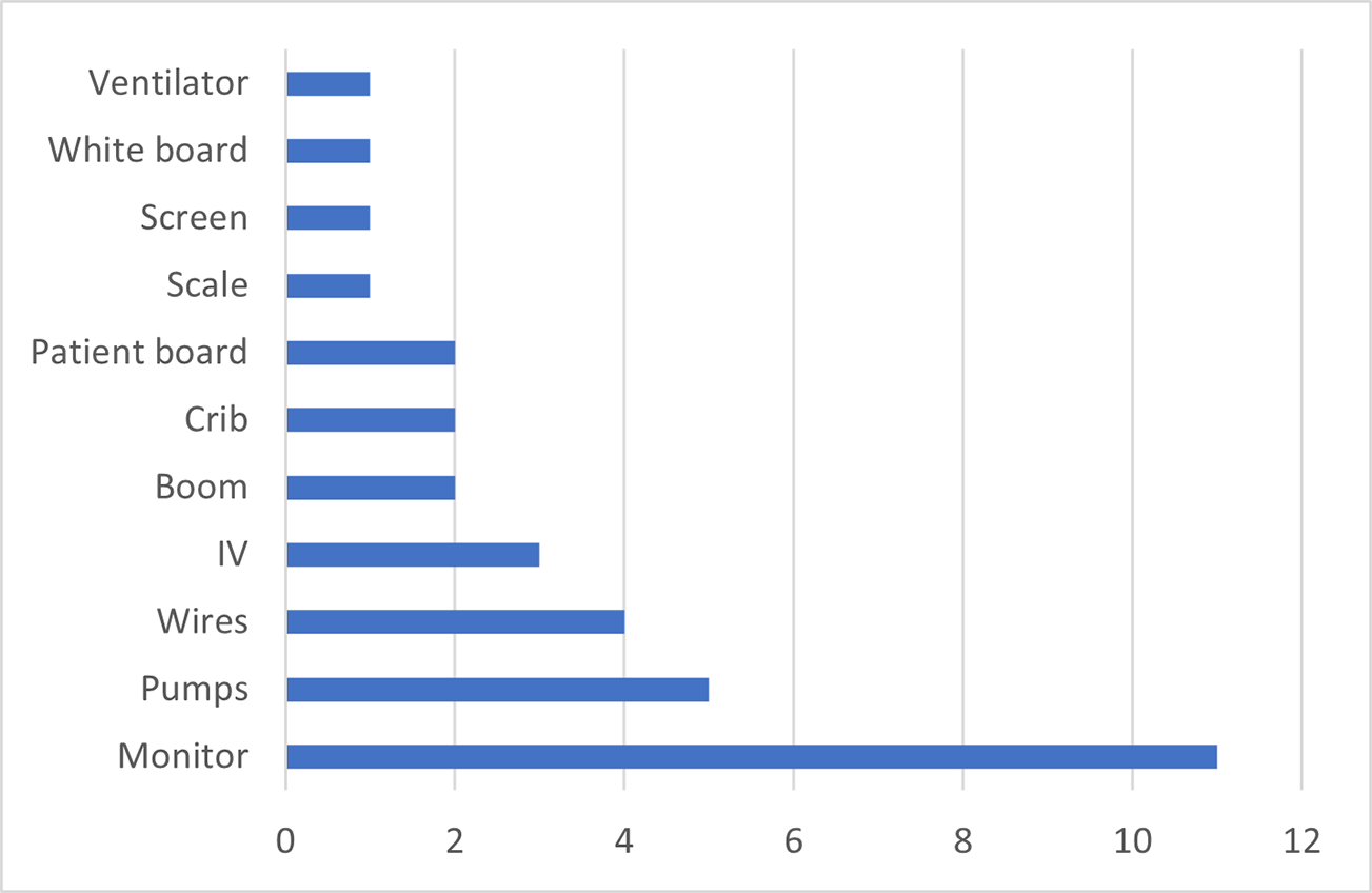
Nitric oxide tank, wires, ventilators, booms, and ECMO machine were the equipment involved in most of the disruptions (82%) in the RT zone (Figures 4 and 5). Bumps, trips, and stretching to reach the equipment were related to lack of space due to large-sized equipment, the high number of staff, and high traffic in the RT zone. The process of transferring the patient to a different bed caused a higher number of disruptions due to the relocation of the equipment and readjusting of wiring and tubing to avoid disconnection in the middle of the patient transfer. Forty percent of major FDs occurred during bed transfer. Figure 6 demonstrates examples of the disruptions happening in the RT zone. RT was constantly bumping into the other RT and the boom when getting out of the cluttered and crowded RT zone (a). The RT also experienced challenges with regard to the positioning of the ventilator, with the RT getting stuck to the ventilator, bumping into the ventilator, or having to stretch and reach excessively to adjust wires to the ventilator or boom (b). This type of disruption was also frequently observed during other tasks, such as setting up additional ventilators (f). Due to inadequate space, when multiple RTs were involved in the procedure, the second RT needed to reach excessively to conduct their tasks on the patient bed (c). Half of the observed disruptions in this zone are related to the rearrangement of the nitric oxide tank and wires (d). There were also instances when clinical staff had to hop over wires or bend forward to move out of the RT zone (e). Movement of the RT resulted in FD mainly from bumping into other personnel and equipment as they maneuvered the equipment. Disruptions also related to poor ergonomics as staff had to bend and stretch to reach equipment.
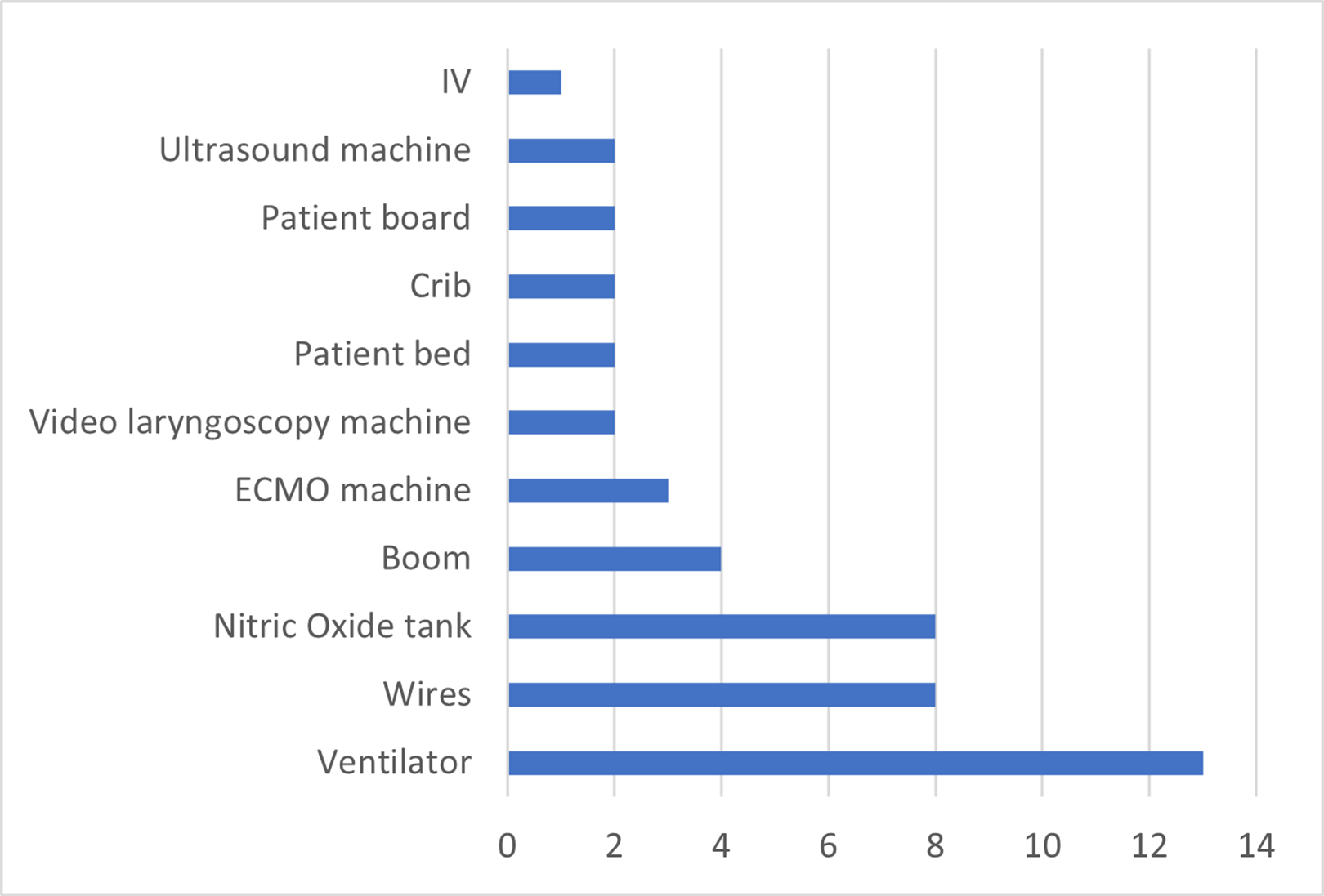
Equipment involved in flow disruptions in the respiratory therapists zone in pediatric intensive care unit.
Equipment involved in three scenarios.
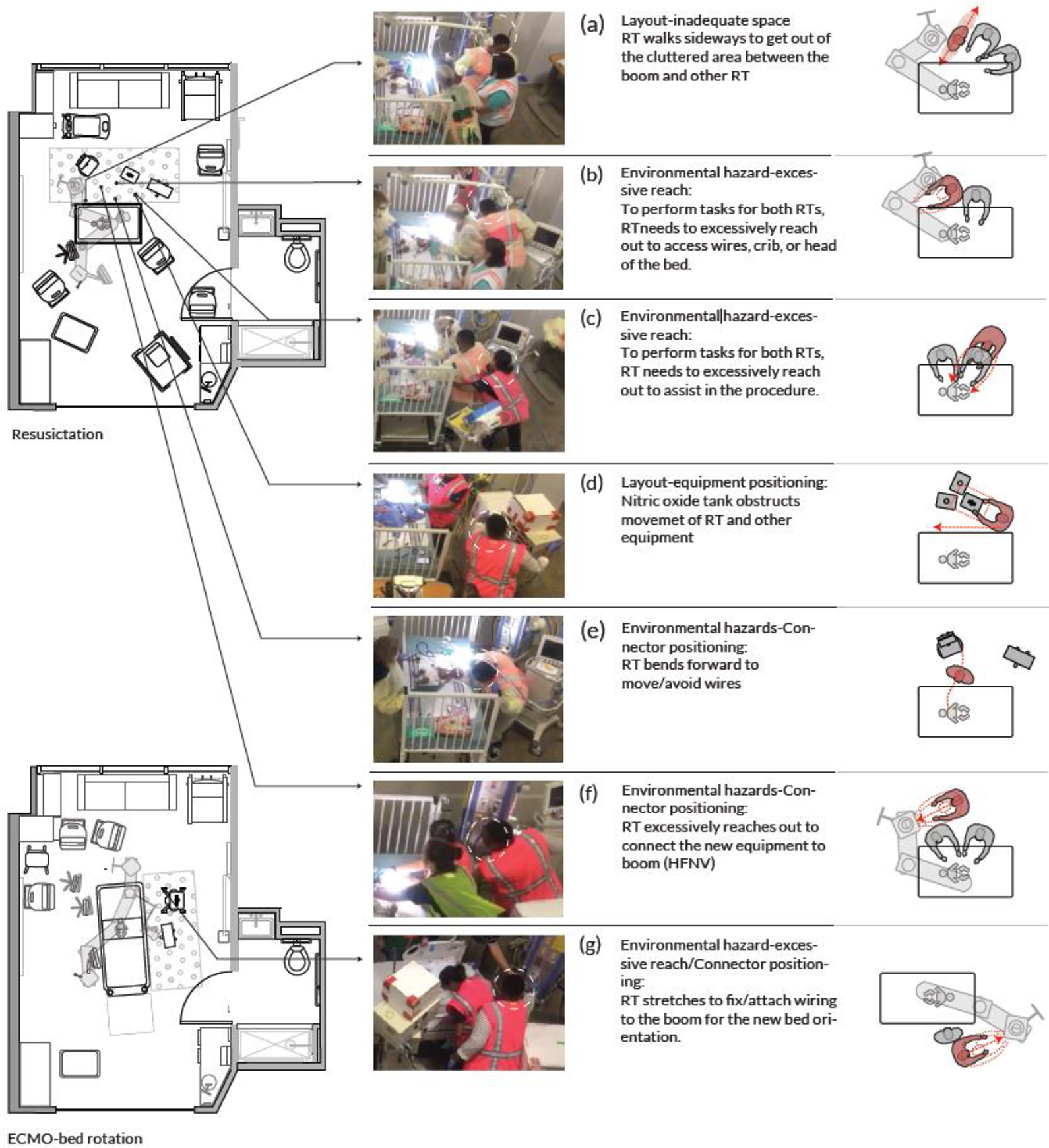
Flow disruptions in the respiratory therapists zone.
Nurse Zone
FD characteristics
The subtypes of FDs observed in the nurse zone were mostly (86%) coded as impeded visibility, excessive reach, and equipment positioning. These events happened in the nurse zone mainly because of inadequate space, the arrangement of the monitor on the boom, and the location of pumps. The majority of the disruption events observed in the nurse zone were minor disruptions (78%).
Equipment, spatial constraints, and clinical context
Monitor, pumps, and boom were involved in most disruptions (79%). Figure 5 depicts equipment placement, and Figure 7 depicts FD related to equipment placement in the nurse zone. Most FDs in the nurse zone occurred after rearranging (rotating) the room for ECMO bedside surgery. Figure 8 demonstrates some of the disruptions occurring in the nurse zone. A considerable number of disruptions in the nurse zone (43%) were due to impeded visibility to other team members and the physiologic monitor by the boom (a, b). The location of pumps at the head of the crib frequently contributed to disruptions (22%) (Figure 8c). Additional FD was related to reaching and stretching to access equipment or the patient (Figure 8c, d). Tangling of wires and tubing also created major disruptions in the nurse zone (e). Subsequent FDs were created as staff removed equipment to create clear paths for travel (f, g).
Equipment involved in disruptions in the nurse zone.
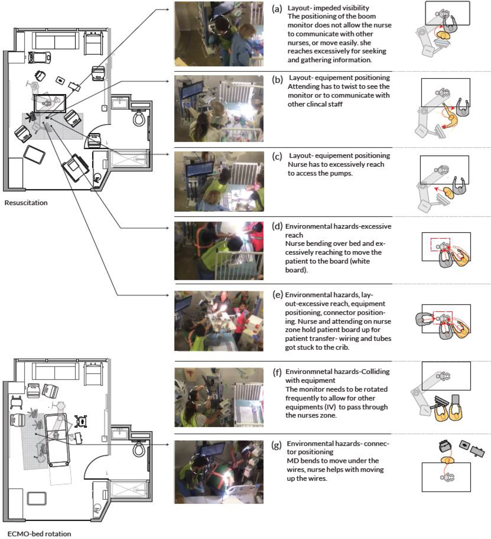
Flow disruptions in the nurse zone.
Head of the Patient’s Bed
FD characteristics
Equipment, furniture positioning, inadequate use of space, and excessive reaching were the categories of disruption events observed in this zone. The zone at the head of the patient bed accounted for 10% of all disruptions. Half the disruptions in this zone (50%) occurred when rearranging the room for ECMO, rotating the bed, and readjusting wiring and tubing. Nearly half the disruptions observed in this zone were major disruptions.
Equipment, spatial constraints, and clinical context
The patient board, wires, and crib were involved in a majority of disruptions (88%) in this zone. FDs were related to bringing ECMO equipment and personnel into the room. The majority of the disruptions at the head of the patient bed occurred when the patient was being transferred from the crib to the rotated patient bed (also shown in Figure 8e). After the bed rotation, inadequate space at the head of the patient bed remained a challenge, and continuous shifting of the equipment cart, ECMO pump, and ventilators was observed.
The Foot of the Patient’s Bed
Equipment positioning and excessive reaching were the subtypes of disruption events coded and observed in this zone. Although only a few disruptions (5%) took place at the foot of the patient bed, half the disruptions were minor, and the other half were major disruptions. Video laryngoscopy machine and bedside table were involved in the disruptions in this zone.
Other Zones
A small percentage of disruptions throughout the three scenarios happened in the nurse support zone (5%). These disruptions happened during room preparation and emergency management of the decompensating patient. Only 2% of all disruptions occurred in the Transition Zone 2 (corridor next to toilet door). Figures 9 and 10 demonstrate the subtype of disruption and severity of disruptions in each zone during these simulations.
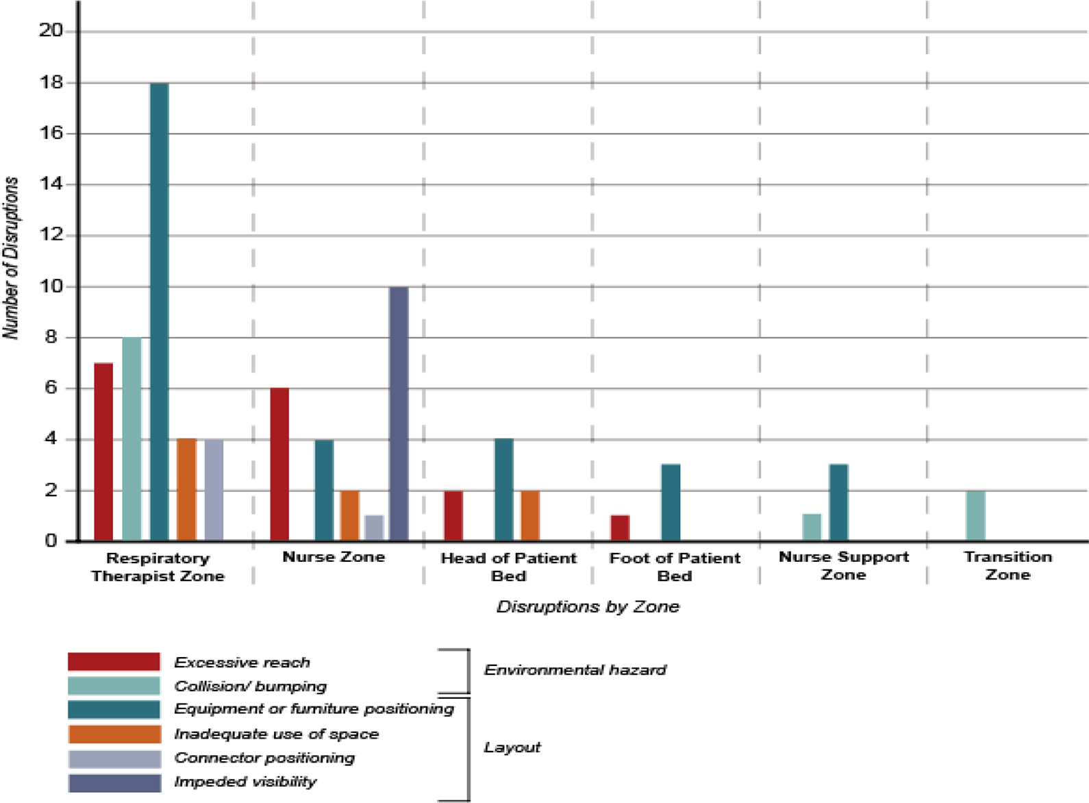
Frequency and type of disruptions in each pediatric intensive care unit zone during simulations.
SFD Severity Map
The majority of disruptions occurred before the bed rotation (80%). Minor and major disruptions were observed in the four zones around the patient bed before and during bed rotation. However, after the bed rotation, major disruptions were only observed in the RT zone. Additionally, no FDs were observed at the foot of the patient bed after the rotation.
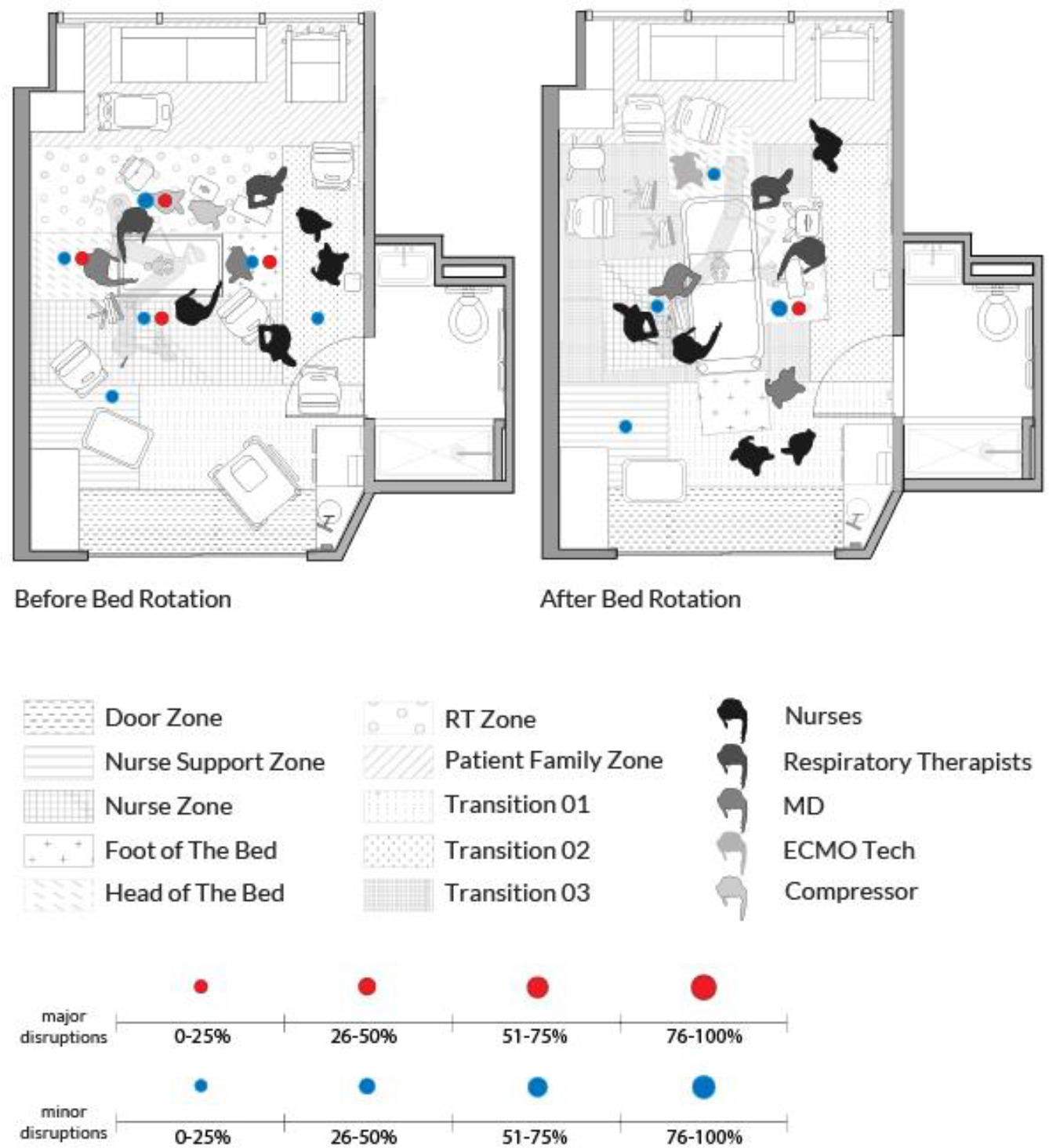
Severity of disruptions in the pediatric intensive care unit zones before and after patient rotation.
Discussion
ICU patient room design should support multiple configurations of staff and equipment layouts. Neglecting to understand how the design and layout of planned clinical spaces impact FD may result in major challenges in future built spaces. High-fidelity simulations better represent work as done, unveiling disruptions and interruptions to workflow and care delivery. While clinical teams can verbalize potential challenges during postsimulation debriefs, it is hard to clearly visualize all the simultaneously occurring events and interactions. The analysis of simulations identified both major and minor FDs related to layout and environmental hazards, mainly in the RT and nurse zone. This method of analyzing simulations conducted in a physical mock-up is extremely valuable since it allows clinical and design teams to clearly visualize and document the location and types of potential challenges that can be anticipated in a proposed space. This information can then be used to make changes to process, operations and future iterations of the design.
In this study, FD analysis first demonstrated the need to clearly identify workflow zones, especially the zone for the RT workflow. Next, the defined zones and identified challenges clarified the need for adequate space at the RT zone and at the head of the patient bed. Finally, the FD analysis helped in understanding how the built environment impacted the movement of equipment and personnel. FDs were mostly observed in the RT zone and the head of the patient bed due to inadequate space at the head of the patient and the RT zone for RT equipment. The positioning of the equipment in the nurse zone contributed to FDs in this zone.
Research suggests that inadequate space and equipment-related ergonomics impact FDs in critical care environments (Wahr et al., 2013); however, previous research has not studied the involvement of RTs in the ICU FDs. In this study, FDs were frequently observed in the RT zone and posed serious challenges to the RT workflow and patient treatment. The RT plays a critical role in ICU care, directly interacting with the patient and equipment to administer mechanical ventilation, assist with airway management, monitor oxygen levels, and administer respiratory treatments (Tu et al., 2020). This study demonstrated that the patient transfer from the crib to a rotated bed occurred mid-procedure because of the small size of the room. Patient transition and moving the bed mid-procedure poses a significant risk due to the presence of wiring and tubing attached to the patient. This process is particularly hazardous for vulnerable infant patients, considering the higher volume of blood circulating through the ECMO circuit in relation to their total blood volume. Patient transition and moving the bed mid-procedure is a dangerous process considering all the wiring and tubing attached to the patient; however, this event occurred to accommodate space for ECMO procedure, equipment, and personnel at the head of the patient. This simulation was able to identify the FDs and challenges in all ICU zones and the FDs associated with this move and rotation.
Findings of this evaluation suggest that a wider ICU room (by 2–3 ft.) which allows for adequate space at the head and foot of the bed, can better accommodate the spatial needs of the RT team and ECMO personnel and potentially prevent the need to rotate the bed, which resulted in several disruptions. ICU room design should also account for the simultaneous presence of large-size equipment such as ventilators and ECMO machine at the head of the patient, the connection of this equipment with one another, and the location of outlets in the ICU for all the RT equipment. The additional space could also help to maintain the 6 ft. of sterility for procedures around the patient bed.
The location of the monitors in the nurse zone impacted the nurses’ access to the monitor and also made the communication between ICU nurses and the clinicians outside ICU challenging. ICU nurses may communicate with clinicians outside the ICU during a procedure when using the alarm “code” to obtain the latest information about the patient or to receive guidance during unexpected scenarios. Communication challenges are common among the ICU team (Grant, 2015), and a layout that makes clinician communication challenging may lead to delayed response time, inefficient care, and decreased safety (Dingley et al., 2008). Positioning the monitor centered and above the bed or further away from the bed may help with accessing the information and with enabling visual access to the corridor; however, the suggested placement would also need to be tested during scenarios for other possible disruptions.
A high percentage of disruptions observed in this simulation was minor disruptions; however, considering the direct relationship between the rate of minor disruptions and major disruptions (Joseph et al., 2019), minor disruptions in the short scenario period could inform about the potential major disruptions and errors in projected design for the built PICU. In this study, the identified latent conditions were addressed through process and operational improvements.
Limitations
In this study, the researcher observed and coded three scenarios in one simulated PICU environment based on an existing taxonomy of disruptions. The short length of the simulations in comparison to actual procedures could be one of the shortcomings of this study. Although an experienced coder observed and coded these videos, another limitation could be the utilization of a single coder. The equipment used for this simulation was primarily actual equipment, but, in some instances, cardboard models were also utilized. Simulated equipment used in the study might have contributed to some of the minor disruptions observed in this study. Care delivery is so variable in different organizations and highly influenced by process, the micro work system, and culture. Another limitation of the study relates to the nature of the care delivery process and the specific FDs observed in this study. These events described in the care delivery process may not necessarily be generalizable.
Conclusion
This study evaluated FDs in a PICU room in a three-phase scenario and found a high number of FDs in the RT zone, nurse zone, and head of the patient bed. Rethinking ICU design according to the needs of the medical teams and enacting different clinical scenarios with high traffic of equipment and personnel could help understand the challenges related to layout and equipment positioning. This could help in creating a design that minimizes excessive movements in the ICU environment and supports staff workflows. The findings from this simulation-based evaluation of mock-ups in the ICU indicated the need for a wider ICU design with adequate space around the patient’s head and the RT zone to accommodate for complex scenarios including different respiratory equipment. Architects need to understand the utilization of functional ICU zones and make design decisions based on specific clinical needs in each ICU zone.
Implications for Practice
The study demonstrates the flow disruption coding method for evaluating and analyzing minor and major environmental hazards and layout issues in different PICU zones.
This study highlights the critical role of the respiratory therapist in ICU care and the need to clearly designate a zone for the respiratory therapist in ICU rooms.
FD analysis could help in understanding how the built environment impact the movement of equipment and personnel.
This study suggests that a wider ICU room with adequate space at the head and foot of the bed, can better accommodate the spatial needs of the RT team and ECMO personnel.
Footnotes
Acknowledgment
The authors would like to acknowledge the partial funding support by Children’s Healthcare of Atlanta.
Declaration of Conflicting Interests
The authors declared no potential conflicts of interest with respect to the research, authorship, and/or publication of this article.
Funding
The authors received financial support for the research, authorship, and/or publication of this article: This study was supported partially by Children’s Healthcare of Atlanta.