
Abstract
We numerically demonstrate trapping and rotation of particles using a metasurface formed by arranging nanocavities as a right-handed Archimedes’ spiral. Excited by a 90° linearly polarized beam, a focused surface plasmon polariton (SPP) field is formed at the center of the spiral, and the particle can be trapped by the field. While excited by −45° linearly polarized beams, a vortex SPP field carrying orbital angular momentum is formed, and the particles can be trapped and rotated in the clockwise direction at the vortex field.
Introduction
Since its first demonstration in 1970s, 1 optical manipulation of particles has boosted a rapid progress in science and technology. 2 –7 Particularly, great attention has been paid to the rotation of the micro-objects. 8,9 This is because rotating particles, nanowires, and biology cells enable the studies of rotating motor, 10,11 mixer working in the liquid, 12 and in vivo cell observation and description. 13,14 Many methods have been applied to realize the rotation of the objects. Proposed techniques were based on the shape asymmetry of the object, 15 dual-beam optical trap, 16 –18 and the transfer of the optical angular momentum. 19 –22 Among them, the transfer of the optical angular momentum is a commonly used rotation strategy, because it does not rely on the intrinsic properties of the particle. 23,24 Vortex beams are known to carry the orbital angular momentum (OAM), which can be transferred to the object, exerting an optical orbital torque to the object. 25 –27 In recent years, the excitation of surface plasmon polaritons (SPPs) provides a promising way to generate the vortex beams. The SPPs, which are propagating excitons induced by collective oscillations of electrons at metal/dielectric interfaces, 28,29 have attached great interest in highly focused excitation 30 and plasmonic lens structures. 31,32 Owing to its intriguing properties, such as spatial confinement and field localization and enhancement, the SPPs were wildly used in biosensing, 33 nanofocusing, 34 optical information technologic, 35 and optical manipulation. 36 –38 There has been shown that radially polarized beam is an optimal SPP excitation for plasmonic structure. 39 The circularly polarized waves carry spin angular momentum (SAM). The SAM can be converted into OAM using plasmonic device. 24,40 Fruitful results that transfer the SAM into OAM have been realized by circularly polarized and radially polarized beam excitation.
However, most of these strategies require manipulation of either the polarization state 41 or the phase front of the illuminating beam to generate optical angular momentum. 11 Moreover, for uniform linear polarization waves, there are some challenges to create OAM since it does not carry any optical angular momentum. To solve these challenges, metasurface, which is composed of designed scatters arranged with subwavelength separation, shows a good character of controlling the SPP field. 42,43 Interactions between light and nanoscale metal with chiral structures show analytically interesting behaviors. 44 The chiral structure consists of a set of split curved slits that could generate the optical vortex. 45 The optical response of the surface plasmon is sensitive to the polarization state of the incident light, 46 which gives us a way to generate OAM by linearly polarized waves. In this work, we realized a near-field OAM with a linear polarization wave using a gold film with an elaborate metasurface. The metasurface was designed by arranging pairs of nanocavities geometrically as a right-hand Archimedes’ spiral. We show that by changing the orientation of the linear polarization, the SPP field can be switched between the vortex field and the focusing field. Moreover, the metasurface can be used to generate OAM by both linearly, circularly, and elliptically polarized excitation.
Results
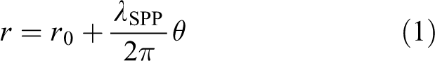
The metasurface was formed by nanocavities embedded in the gold film. A nanocavity in a gold film scatters light polarized perpendicular to it. 28 We have performed numerical simulation using Lumerical, a finite-difference time-domain solver from Lumerical, Inc. The simulation model is shown in Figure 1(a). We used the perfectly matched layer absorber boundary condition. In the simulation, the wavelength of the incident light λ 0 is set as 808 nm. The reason for using 808-nm laser is that it exhibits a low water absorption rate and there is no obvious thermal effect. The size of the gold film and nanocavity is 4 × 4 × 0.25 μm3 and 0.4 × 0.1 × 0.25 μm3, respectively. The long axis of the nanocavity is in the x-direction. The simulation region is 5 × 5 × 2 μm3, and a mesh with a cell size of 7.8 × 7.8 × 7.8 nm3 was used. The electric field of the SPP field was only polarized in the z-direction. The SPP emission pattern of a subwavelength aperture is approximately that of an in-plane dipole (Figure 1(b)). Figure 1(b) shows that the nanocavity scatters the incident light, which is perpendicular to its long axis. Figure 1(c) and (d) shows a pair of these nanocavities embedded in a gold film illuminated by a 90° linearly polarized wave. The size of the film and the nanocavities is the same as in Figure 1(a) and (c). The nanocavities are perpendicular to each other and spaced at a distance of 100 nm apart. The simulation result (Figure 1(d)) shows the SPP emission pattern of a series of annulus. Because each nanocavity can be regarded as a dipolar oscillator, and only the component of the wave that is perpendicular to the long axis of nanocavity can be scattered by the nanocavity.
The metasurface was designed by arranging pairs of nanocavities geometrically as a right-hand Archimedes’ spiral (Figure 2(a)). The right-hand Archimedes’ spiral structure can be described in cylindrical coordinates as 47
where r 0 is a constant (in Figure 2(a), r 0 = 2λ SPP) and θ is the azimuthal angle from 0 to 2Π, and λ SPP is SPP wavelength. The λ SPP can be calculated by 34
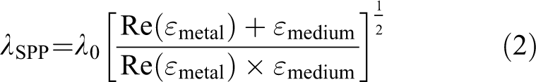
where λ 0 is the wavelength of the incident light beam, Re(ε metal) is the real part of the dielectric constant of the metal, and ε medium is the dielectric constant of the medium. The corresponding λ SPP of 808-nm laser is 787.5 nm. Figure 2(a) shows the top view of the metasurface. The element of the nanocavities was two perpendicular nanocavities shown in Figure 1(c). The angle between nanocavity pair and its neighboring nanocavity pair was 12° (inset of Figure 2(a)). So, the metasurface is composed of 31 pairs of the nanocavities. Figure 2(b) schematic shows the structure of the metasurface. The size of the gold film is 6 × 6 × 0.25 μm3. The simulation region is 8 × 5 × 2 μm3, and a mesh with a cell size of 7.8 × 7.8 × 7.8 nm3 was used.
Calculated z-component electric field Ez for the nanocavities excited by the linearly polarized beam. The length L and width W of the nanocavities were 400 and 100 nm, respectively. (a) Model of a nanocavity embedded in a gold film excited by a 90° linearly polarized beam. (b) The calculated Ez . (c) Model of two nanocavities embedded in a gold film excited by a 90° linearly polarized beam. The nanocavities are perpendicular to each other. The distance between two nanocavities S was 100 nm. (d) The calculated Ez .
Geometry of metasurface. (a) The schematic of the metasurface. The inset shows the geometry of the nanocavities. The length L and width W of the nanocavities were 400 and 100 nm, respectively. The distance between two nanocavities S was 100 nm. (b) The metasurface was on a glass substrate, and the liner polarized laser was launched from the bottom of the glass.
Figure 3(a) shows z-direction SPP vortex field distribution of the metasurface under right-hand circular polarized optical excitation calculated using finite-difference time-domain (FDTD) method. Four field petals within 2Π azimuthal range can be observed. The four field petals indicate the vortex with a topological charge of 2. 42 This corresponds with Figure 3(b) that the phase of the SPP field has two abrupt phase jumps from −π to +π within a 2π azimuthal range. The intensity of the z-direction SPP field was a series of annular (Figure 3(c)). The curve in Figure 3(c) shows that the field distribution fits the second-order Bessel function of the first kind. Angular momentum of this field can be transferred to the particle and finally induced the rotation of the particle. Figure 3(d) to (f) shows the situation under the left-hand circularly polarized optical excitation. The SPP field was focused at the center of the spiral (Figure 3(d)). Figure 3(e) shows that the phase does not have any jumps within a 2π azimuthal range means that does not feature the helical structure. As a result, the SPP field does not carry any angular momentum. Figure 3(f) shows the intensity of this field. A focusing field was obtained. The curve in Figure 3(f) shows that the field distribution fits the zeroth-order Bessel function of the first kind. Particles in such field can be trapped at the center of the focus. Then, the metasurface was illuminated by the linearly polarized beam to excite the SPP field. Figure 3(g) shows z-direction SPP field distribution under the excitation by −45° linearly polarized beam. Four field petals within 2Π azimuthal range can be observed. The phase of the SPP field has two abrupt phase jumps from −π to +π within a 2π azimuthal range (Figure 3(h)), indicating that the SPP field was associated with vortex with a topological charge of 2. Figure 3(i) shows the intensity of the SPP field. A near-field vortex field with a donut shape was generated around the spiral. The curve in Figure 3(i) shows that the field distribution fits the second-order Bessel function of the first kind. Angular momentum of this field can be transferred to the particle and finally induced the rotation of the particle. Compared to Figure 3(a) to (c), the variation tendency of the SPP field was similar to the situation under right-hand circular polarized excitation. Figure 3(j) to (l) shows the situation under 45° linearly polarized optical excitation. Similarly, with the situation under the left-hand circular polarized optical excitation, the SPP field was focused at the center of the spiral (Figure 3(j)). The phase does not have any jumps within a 2π azimuthal range means that does not feature the helical structure (Figure 3(k)). As a result, the SPP field does not carry any angular momentum. Figure 3(l) shows the intensity of this field. A focusing field was obtained. The curve in Figure 3(l) shows that the field distribution fits the zeroth-order Bessel function of the first kind. Particles in such field can be trapped at the center of the focus.

Calculated results of the metasurface. (a–c) Results under the right-hand circularly polarized waves. (a) Ez , (b) phase distribution of Ez , and (c) intensity distribution. The curves show the intensity distribution at the dashed line. (d–f) Results under the left-hand circularly polarized waves. (d) Ez , (e) phase distribution of Ez , and (f) intensity distribution. The curves show the intensity distribution at the dashed line. (g–i) Results under −45° linearly polarized waves. (g) Ez , (h) phase distribution of Ez , and (i) intensity distribution. The curves show the intensity distribution at the dashed line. (j–l) Results under 45° linearly polarized waves. (j) Ez , (k) phase distribution of Ez , and (l) intensity distribution. The curves show the intensity distribution at the dashed line.
To show that the metasurface can be used to realize selectively manipulation of micro-object, optical forces (

where

where ⊗ is the dyadic product,

Calculated optical force and potential for the SPP field. (a) Calculated fx and fy at the x-offset along the dashed line in the insert under 45° linearly polarized waves and the trapping potential in the x-direction. (b) Calculated fx and fy at the y-offset along the dashed line in the inset under 45° linearly polarized waves and the trapping potential in the y-direction. (c) Calculated fx and fy at the x-offset along the dashed line in the insert under −45° linearly polarized waves and the trapping potential Ux in the x-direction. The shaded areas denote the primary ring. (d) Calculated fx and fy at the y-offset along the dashed line in the insert under −45° linearly polarized waves and the trapping potential in the y-direction. The shaded areas denote the primary ring. SPP: surface plasmon polariton.
Generally, a polarized wave can be written as

where Ex and Ey are the x-component and y-component of the electric field, respectively. θ is the phase difference of Ex and Ey . For the situation Ax = Ay , when 0 < θ < 180° and −180° < θ < 0, the polarization states are left hand and right hand, respectively. Especially, when θ = 90° and θ = −90°, the waves are circularly polarized. When θ = 0 and θ = 180°, the waves were 45°linearly polarized and −45° linearly polarized, respectively. The front calculation shows that the metasurface can realize rotation and trapping particles under the circularly polarized excitation and linearly polarized excitation. Figure 5, as an example, shows the intensity and phase distribution of the SPP field, that is, the metasurface under elliptically polarized excitation. When θ = −150°, −135°, −120°, −60°, −45° and −30°, a focusing spot was formed at the center of the spiral (Figure 5(a1) to (f1)). The phase does not feature the helical structure (Figure 5(a2) to (f2)). When θ = 30°, 45°, 60°, 120°, 135°, and 150°, a near-field vortex field with a donut shape was generated around the spiral (Figure (g1) to (l1)) and the phase features the helical structure (Figure (g2) to (l2)). Figure 5 confirms that under elliptically polarized excitation, the metasurface can still realize trapping or rotating the particles.

Results under the elliptically polarized excitation. (a1)–(l1) Intensity distribution for the phase difference was −150°, −135°, −120°, −60°, −45°, and −30°, respectively. (a2)–(l2) Phase distribution for the phase difference was −150°, −135°, −120°, −60°, −45°, and −30°, respectively.
Conclusions
A metasurface was proposed to realize particle manipulations. Under the excitation of 45° linearly polarized beams, a stable near-field focusing field was formed at the vicinity of the spiral origin. By −45° linearly polarized beams excited, a donut-shaped vortex field with a topological charge of 2 was formed. The particles can be trapped and rotated in the clockwise direction. The resultant optical force and the corresponding trapping potential have been numerically analyzed using the FDTD method. We further demonstrate that under elliptically polarized excitation, the metasurface can still realize trapping or rotating particles. These results are expected to find application in studying the properties of protein or DNA and conformational change in the solution.
Footnotes
Declaration of conflicting interests
The author(s) declared no potential conflicts of interest with respect to the research, authorship, and/or publication of this article.
Funding
The author(s) disclosed the receipt of the following financial support for the research, authorship, and/or publication of this article: This work was supported by Tip-top Scientific and Technical Innovative Youth Talents of Guangdong Special Support Program [No. 2015TQ01X267].