
Abstract
In this work, we report a graphene-alkaline lignin-poly(3,4-ethylenedioxythiophene) polystyrene sulfonate composite as a transparent conductive electrode for indium tin oxide-free optoelectronic devices. The composite was prepared by dispersing exfoliated graphene-alkaline lignin into aqueous poly(3,4-ethylenedioxythiophene) polystyrene sulfonate. The effect of graphene concentration on the electrical and optical properties of graphene-alkaline lignin-poly(3,4- ethylenedioxythiophene) polystyrene sulfonate was studied. The graphene-alkaline lignin-poly(3,4- ethylenedioxythiophene) polystyrene sulfonate thin films exhibit excellent electrical conductivity and high transparency properties. The electrical conductivity is further increased by 1.9 ± 0.01 × 10³ times when graphene content was augmented in the composites; however, the optical transparency was reduced due to the high optical absorbance of graphene. In this condition, the conductivity and optical transparency are as high as (4.19 ± 0.01) × 103 S/cm and 94.2%, respectively. This achievement is attributed to the organization of higher ordered network between conductive exfoliated graphene and poly(3,4-ethylenedioxythiophene) chains that induced a better conducting channel for charge transportation. The poly(3,4-ethylenedioxythiophene) chains act as a bridge connecting the graphene flakes, which, in turn, facilitate the movement of hole charges between them.
Introduction
Transparent conductive electrodes (TCEs) are an essential component for various optoelectronic applications such as electronic display, organic photodetectors, organic solar cells, and organic light-emitting diode (OLED). 1 Currently, indium tin oxide (ITO) coated on rigid glass is the most widely used material for TCE. 2,3 However, the high price and limited availability of indium has resulted in the need of finding an alternative TCE for the next generation of optoelectronic devices. 4 –7 The components needed for the next generation of TCE have to be flexible, 8 transparent, and highly conductive materials. Although ITO demonstrates high electrical conductivity and optical transparent properties, it is not applicable for bending and stretching for flexible applications. 9 Breakage on the ITO film due to mechanical bending or stretching can lead to a reduced quality of electrical properties. 10 In addition, high acidic ITO glass electrode creates complication for device degradation due to electrode–organic layer material diffusion. 11
Over the last two decades, research on TCE materials has been carried out. In the early stages, semiconductor materials such as fluorine-doped tin oxide, 12 zinc oxide, 13 and aluminium zinc oxide 14 have been considered as potential TCE, as these materials exhibited high electrical conductivity and high transparency in the visible light region as compared to conventional ITO. With the ongoing development in nanotechnology, the search for new alternative TCE materials intensified and expanded to include metal grids, 15 conductive polymers, 16 carbon nanotubes, 17,18 and graphene. 19 Due to the limitation of the ITO electrode, graphene is desired because it offers tremendous advantages in optoelectronic devices. Graphene, which has high electrical conductivity, transparency, and chemical stability, became one of the alternatives to replace the electrode based on ITO. 20
Despite such advantageous properties of graphene, it is not practical for graphene to be used as TCE for most optoelectronic devices because graphene with a single atomic thickness has a zero energy gap, which makes it difficult to control the movement of charge carriers into and out of the devices. The structure of pristine graphene should be modified so that the energy gap can be altered to align with the energy level of the active layer. Energy-level matching is a key factor for realizing efficient optoelectronics, such as OLEDs. 21 Graphene polymer nanocomposite has shown promising properties due to the unique properties of graphene and polymer, which changes their optical and electrical behavior. 22 –25 As a solution, graphene should be prepared in the form of composites with other conducting polymeric materials. 26 For instance, the common conductive polymers used in the production of graphene composites such as polyaniline, 27 polystyrene, 28 and polycarbonate. 29 Poly(3,4-ethylenedioxythiophene) polystyrene sulfonate (PEDOT-PSS) is a high potential conductive polymer for this purpose due to its extremely high transparency at the visible region and high electrical conductivity. In addition, polymer PEDOT-PSS may also improve the dispersion of graphene in the composite, generating highly conductive and optical transparency composite material. 16 However, the conventional approach for graphene synthesis required high temperature process and delicate deposition process for TCE application. For example, direct graphene synthesis by electrochemical exfoliation produces nonsoluble graphene 22 while graphene synthesize by exfoliation of graphene oxide requires a reduction process to produce graphene. 23 In our work, we demonstrated novel low-temperature graphene composite synthesis using a green material surfactant. Here, we report our novel subsequent work on the synthesis of alkaline lignin (AL)-stabilized graphene composed of PEDOT-PSS (GL-PPS) and a new solution process of large-area graphene by spin-coating method for TCE application. By controlling the graphene content in the composite, highly conductive and optical transparency GL-PPS film can be obtained and can be used as potential TCE in optoelectronic devices application.
Materials and methods
PEDOT-PSS in aqueous solution (PH 1000) was acquired from the Heraeus group (Hanau, Germany) with a concentration range from 1.0% to 1.3% by weight. The weight ratio of PEDOT-PSS in the solution was 1:2.5. Both AL and the graphite powder were purchased from Sigma Aldrich (St. Louis, Missouri, USA). All chemicals were analytical reagent grade and used as received without any further purification process. Deionized water, which was used throughout the experimental process, was obtained from a Merck Millipore Milli Q water purification system.
Preparation of graphene composite
The prepared graphene flake was synthesized via previously reported graphite exfoliation method. 29 About 0.5 mg/mL of AL was added to 20-mL scintillation vials and the AL solutions were both sonicated for 15 min. About 40 mg/mL of graphite was added to the AL solution and all the mixtures were stirred for 15 min at room temperature. The mixtures were then sonicated for 5 h at a temperature below 35°C. The dispersions were left for 24 h and then centrifuged for 90 min at 600 r/min. After centrifugation, the stable graphene dispersion was formed at the upper part of the solution and carefully collected by micropipette. The dispersion was then transferred to a 50-mL Teflon-lined autoclave and annealed for 2 h at 200°C. The graphene dispersion was then mixed with 5 mL of deionized water and centrifuged at 600 r/min for 90 min to remove excess AL from the graphene dispersion. The graphene solution dispersion was vacuum-filtered and graphene sediment was obtained. The sediment was washed three times with deionized water. The colloidal graphene with 100 mg/mL concentration was then prepared by dispersing 100 mg of graphene sediment into deionized water. Commercial aqueous PEDOT-PSS solution was filtered using a 0.45-µm polytetrafluoroethylene filter syringe to remove unwanted large particles. Then, the chosen amount of graphene solution was added into the PEDOT-PSS solution in the ratio by wt% as presented in Table 1. All the mixtures were vigorously stirred for 3 h and homogenous graphene composites were obtained.
The ratio in weight percentage of GL-PPS composites with labels.

GL-PPS: graphene-alkaline lignin-PEDOT-PSS; PEDOT-PSS: poly(3,4-ethylenedioxythiophene) polystyrene sulfonate.
Preparation and characterization of graphene composite thin film
All substrates (quartz and glass) with 1.5 cm × 2.0 cm dimension were cleaned using a sonicator to remove unwanted organic and inorganic impurities. The substrates were cleaned with detergent soap, deionized water, acetone, isopropanol, and ethanol for 10 min for each cleaning agent. Then, the substrates were dried in an oven. The cleaned substrates were treated with oxygen plasma prior to spin coating to increase surface wettability. Next, graphene composite thin films were fabricated through spin-coated technique at 3000 r/min and then the films were annealed on the hot plate at 100°C for 30 min at ambient temperature. The fabricated GL-PPS composite films were treated by dipping the films into methanol solution and annealed on the hot plate for another 15 min to reduce PSS content in the composite. The process was repeated multiple times to obtain thicker films and film treatment with consecutive annealing was conducted after each layer.
Characterization
The optical transmittance and absorption test were carried out by a Perkin Elmer Lambda 900/UV/VIS/NIR spectrophotometer. The structural property of GL-PPS composite thin films was performed on a Bruker/D8 Advance powder X-ray diffractometer (XRD) with CuKα radiation (λ = 0.15406 nm). A SMU Keithley 2400 source meter was used to provide current from 5 mA to 10 mA. For field-emission scanning electron microscopy (FESEM), GL-PPS composite films were analyzed under the Zeiss Supra 55VP FESEM model with a resolution of 1.0 nm at 30 kV. The thickness of the samples was estimated using Veeco Surface Profiler. The electrical properties of the samples were measured with a Hall-Effect measurement system (Ecopia, HMS-5300, Bruker, Keithley, Zeiss and Veeco is the manufacture ) based on the van der Pauw method. The samples were cut into a square shape with size of 1 × 1 cm2 and four contacts were made by soldering indium dots of about 0.5 mm on each of the edges of samples to create ohmic contact with samples.
Results and discussion
Figure 1(a) shows the FESEM image of the graphene thin film deposited on glass substrates, which reveals the homogenous distribution of graphene flakes. After dipping the graphene thin film in water, almost all graphene flakes were detached from the glass surface as confirmed by the appearance of the glass substrate in Figure 1. The desorption of graphene flakes from the glass substrate verified that weak adhesion between graphene flakes and glass substrate was due to the lack of chemical interaction between the functional group of graphene with a glass substrate. Figure 1(b) shows the scanning electron microscopy image of conductive polymer PEDOT-PSS thin film and after dipping this film in water, the layer of PEDOT-PSS is still intact on the glass substrate. Modification of graphene is needed to ensure the modified graphene thin film retains high stability in an aqueous medium. The FESEM images of GL-PPS composite thin films on a glass substrate with a variation of graphene content (in wt%) were collected and presented in Figure 1(c) to (f). The weight percentage ratio of GL-PPS composites with labels used in this work is presented in Table 1. The densely packed orientation of graphene flakes covered with a coating layer of PEDOT-PSS can be clearly identified, which should be beneficial for charge transport and conduction across the thin films. However, the morphology of GL-PPS largely depends on the concentration of the precursor solution (graphene). From FESEM images, exfoliated graphene and segregated nonconductive PSS grain are indicated by the bright and dark regions, respectively. Increasing the amount of exfoliated graphene in the composite solution results in the addition of bright regions, which means that less unwanted insulator PSS are scattered on the composite film surface. Inhomogeneous distribution of insulator PSS is possibly due to the direct and facile wet process to synthesize exfoliated graphene flakes containing surfactant AL, which easily forms an intramolecular linkage with PSS. Even after methanol treatment, partial PSS chain was still intact due to the strong π–π interaction between AL π electron and aromatic structure of PSS particles.
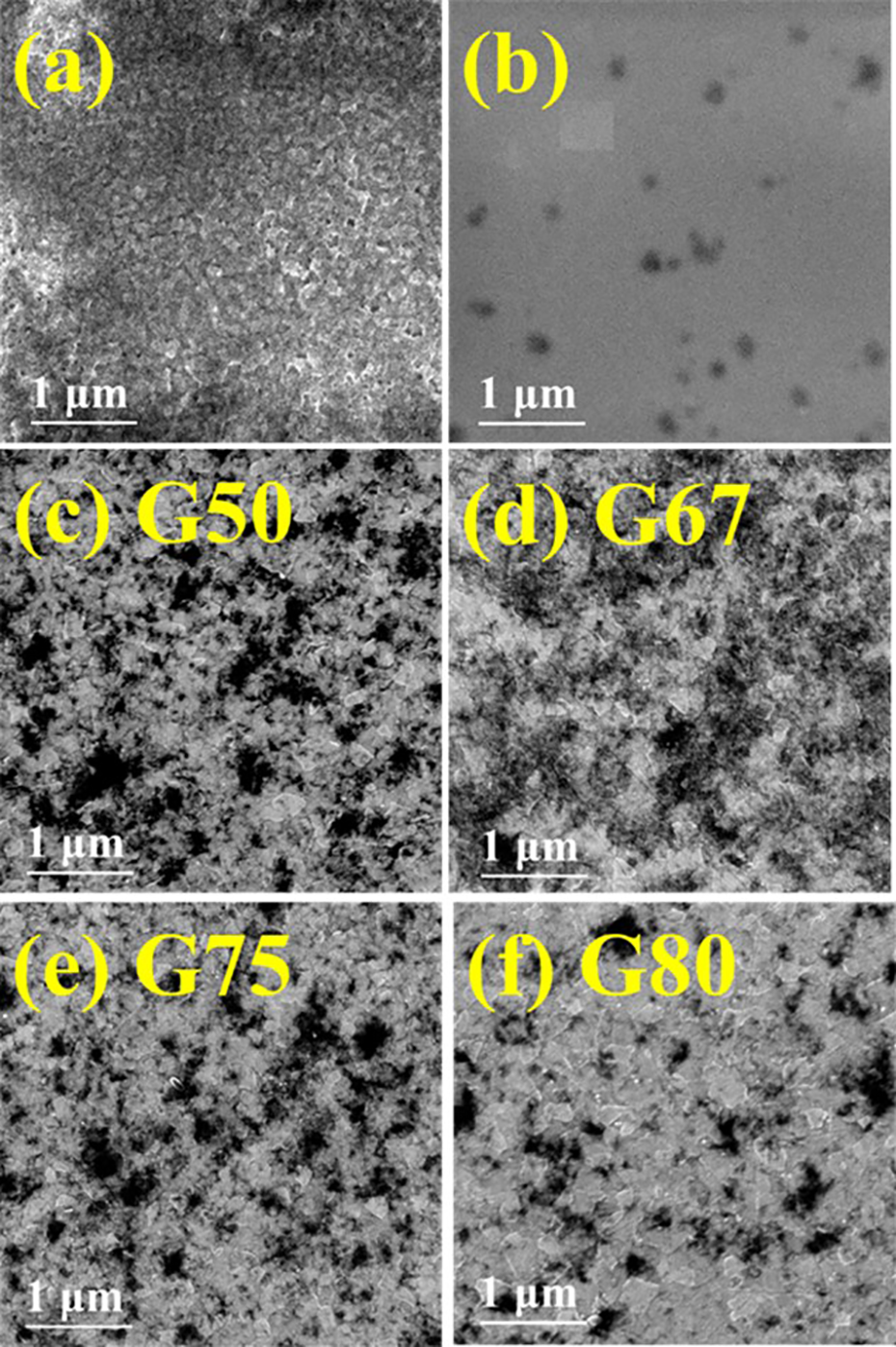
FESEM images of (a) exfoliated graphene, (b) PEDOT-PSS, and (c) to (f) wt% variation of graphene content (G50, G67, G75, and G80) GL-PPS composite thin films. FESEM: field-emission scanning electron microscopy; GL-PPS: graphene-alkaline lignin-PEDOT-PSS; PEDOT-PSS: poly(3,4-ethylenedioxythiophene) polystyrene sulfonate.
The characterization using a surface profilometer has been conducted to provide information regarding the thickness of prepared GL-PPS composite thin films as given in Table 1. Taking into account that the thickness of prepared GL-PPS thin films is in the range of 55–130 nm, this demonstrates that the thickness of the GL-PPS composite film increased with the ratio of graphene content in GL-PPS. The addition of graphene content in the solution increased the viscosity of the composite dispersion and influenced the thickness of prepared GL-PPS composite thin films.
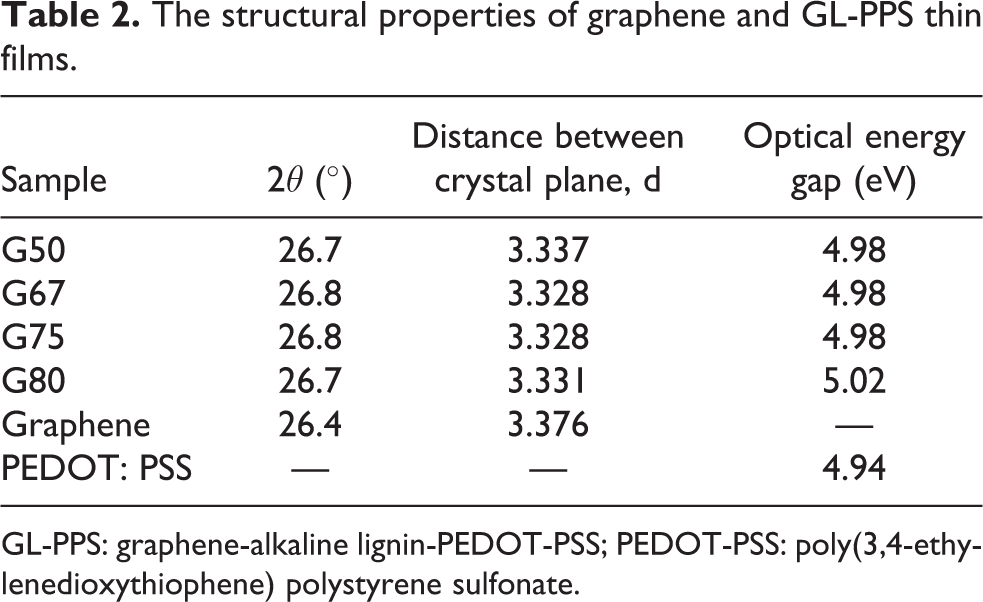
Figure 2 shows the corresponding XRD spectrum for all thin films samples. For graphene thin film, the XRD showed clear 002 diffractions indicating the characteristic graphitic materials. The peak position at 26.4° is similar to the standard XRD pattern of graphite with Joint Committee on Powder Diffraction Standards file number 041-1487. The GL-PPS composite thin films were then compared with the G100 thin films for confirmation of the formation of crystalline structure. For GL-PPS composite thin films, we observed small peak overlapped at the right side of the 002 diffraction peak. This peak is probably from the crystallization structure of treated PEDOT-PSS. According to the literature, PEDOT-PSS has crystal structure where the main peak at 25.6°, 16 and the treated PEDOT-PSS peak may have diffraction peak up to 28.4°. 30 The changes in 002 diffractions indicate the changes in interatomic distance inside graphene atom and at the same time affecting the interatomic distance in PEDOT-PSS that may cause by the internal strain towards each other that might change locally the lattice parameter measured by XRD. 31 A peak shift to a higher angle indicates that expansion of d-spacing in the out-of-plane direction is taking place, which means that lattice under the tensile strain. This also causes the energy gap alteration of the composite materials as interatomic potential between the atoms also changes with the tensile strain. The relationship between the distance between the crystal plane and the change in energy gap was summarized in Table 2.

XRD spectra of graphene and GL-PPS composite thin films. XRD: X-ray diffraction; GL-PPS: graphene-alkaline lignin-PEDOT-PSS; PEDOT-PSS: poly(3,4-ethylenedioxythiophene) polystyrene sulfonate.
The structural properties of graphene and GL-PPS thin films.
GL-PPS: graphene-alkaline lignin-PEDOT-PSS; PEDOT-PSS: poly(3,4-ethylenedioxythiophene) polystyrene sulfonate.
Materials that are used for TCE require high transparency as well as high electrical conductivity. The first criterion that needs to be fulfilled as a candidate for TCE is that the fabricated thin film should have high transparency in visible light, exceeding 90%. 32 To examine the optical properties of GL-PSS composite thin films, the transmittance analysis via UV-Vis spectroscopy was conducted. The optical transmittance spectra of GL-PSS composite thin films are shown in Figure 3. From Figure 3(a), the spectrum of PEDOT-PSS thin film is given as comparison and it is found that the films exhibited high optical transmittance of 97.9%.
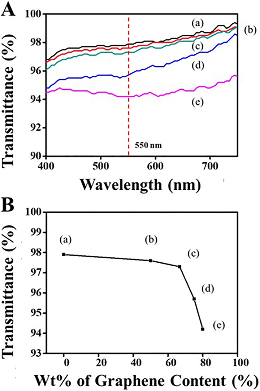
Optical transmission variation for (a) PEDOT-PSS, (b) G50, (c), G67 (d) G75, and (e) G80 thin films. PEDOT-PSS: poly(3,4-ethylenedioxythiophene) polystyrene sulfonate.
After mixing with a certain weight ratio of polymer PEDOT-PSS with exfoliated graphene in the composite thin films, the optical transmittance further decreases with increasing percentage graphene content in composites. As can be seen in the figure, all samples have transparency properties within the range of visible light, 400–800 nm and there is no absorption band observed within that range. Optical transmittance values at a wavelength of 550 nm for each sample are plotted against the weight percentage of graphene content as depicted in Figure 3(b). Thin-film G80 has the lowest optical transmission value of 94.2%. In general, all thin films’ samples possess optical transmittance over 90%, ensuring that GL-PPS composite films meet the criteria of optical properties needed for TCE application.
The second requirement is that the films should have high electrical conductivity (low electrical sheet resistance). There were two electrical characterizations carried out in this study. First, the measurement of sheet resistance was evaluated using a conventional four-point probe method. Second, the measurement of charge carrier mobility and semiconductor type wase handled using Hall Effect technique. All the results discussed in this section are based on measurements at room temperature and the results are presented in Table 3. The electrical conductivity for each sample was listed as the average of measurements taken at the center and edges of the thin film samples.
The electrical properties of graphene, PEDOT-PSS, and GL-PPS composite thin films.
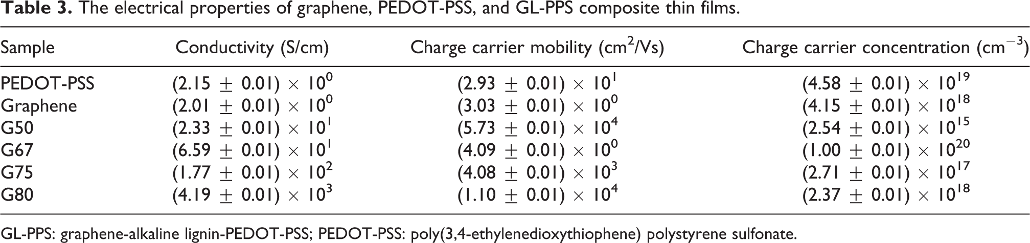
GL-PPS: graphene-alkaline lignin-PEDOT-PSS; PEDOT-PSS: poly(3,4-ethylenedioxythiophene) polystyrene sulfonate.
For graphene thin film, the electrical conductivity is low. However, this value increased to 3.63 S/m after annealing treatment. The conductivity enhancement is likely due to the removal of alkali lignin surfactant and solvent used in the synthesis of graphene dispersion. Also, the increase in surface homogeneity of graphene thin film resulting from heat treatment further improved the electrical conductivity of the film. 33 Although the conductivity showed a significant enhancement, the value achieved is still quite low that affect the efficiencies of organic-based devices, which are mainly caused by two reasons: the small flakes of graphene have incomplete sp 2 carbon on the edge of graphene structure that contributes to defects, and some of these graphene flakes do not touch with each other as can be seen in FESEM image from Figure 1. Thus, the preparation of graphene blended with conductive polymer PEDOT-PSS thin film is likely to improve the conductivity of the films by forming a conductive network between graphene flakes. As can be seen from Figure 4, the electrical conductivity of GL-PPS composite thin films is in the range of 23.3–4190 S/cm for the lowest weight percentage of graphene content 50% to the highest 80%. The electrical conductivity of GL-PPS increased with the additional percentage of graphene content in the composite films. This can be attributed to the fewer presence of insulator PSS particles on the high ratio of graphene in GL-PSS thin film morphology as judged by FESEM analysis from Figure 1. This significant increment may be caused by the attribute of an ordered packing of the thinner and smaller graphene sheets with polymer chain and interfacial π–π interaction. 34

Electrical conductivity variation for (a) PEDOT-PSS (G0), (b) G50, (c), G67 (d) G75, and (e) G80 thin films. PEDOT-PSS: poly(3,4-ethylenedioxythiophene) polystyrene sulfonate.
The conductivity of this study was 1.58 × 10³ S/m lower than commercially available ITO TCE. 35 However, our method emphasizes on the ease of synthesis and the achieved TCE properties are suitable for low cost and solution process optoelectronic fabrication.
The PSS particles can be easily removed via methanol treatment. High concentration of graphene is attributed to the role of methanol to remove insulator PSS from the film surface. There are two processes involved in removing the insulated PSS. Firstly, the hydroxyl functional group (−OH) presents in methanol is highly hydrophilic, which dissolves unwanted hydrophilic PSS. The high dielectric constant of methanol solvent induced screening effects that helped to weaken the Coulomb interaction between PEDOT and PSS. 8 Secondly, the PEDOT and graphene form a strong π–π* bond, which holds the PEDOT molecule 36 during the removal of the PSS as shown in Figure 5. Removal of PSS grains then forced the reorientation of the PEDOT chain that leads to an improved network connection among conductive PEDOT chains and graphene flakes. 10 The PEDOT chains act as a bridge between graphene flakes, which, in turn, facilitate the movement of an electron from one graphene flake to another. This favorable morphology induced a better conducting channel for charge transport that is reflected in the enhancement of electrical conductivity.

Molecular bond of PEDOT: PSS and graphene before removal of PSS. PEDOT-PSS: poly(3,4-ethylenedioxythiophene) polystyrene sulfonate.
From Hall Effect analysis, graphene and PEDOT-PSS thin films have recorded low charge carrier mobility; however, this value demonstrated significant improvement by increasing the graphene inclusion in the GL-PSS composite. There are several factors that influence the mobility of charge carriers, including the mutual interaction between both conductive graphene flakes and polymer PEDOT-PSS that contributes to conductivity. Graphene flakes itself helped in contributing to the conductivity and the synergy created with conductive PEDOT-PSS network intensified the mobility of charge carriers. Furthermore, the significant mobility improvement is associated with the closely packed arrangement of graphene flakes and PEDOT chain through π–π interaction with a continuous conductive network that can provide a direct path for charge carrier transport. As an addition, GL-PSS thin films have p-type semiconductor and this property has similarity with conventional ITO thin films.
The mechanism for the formation of GL-PPS composite at the moment is not yet understood; however, the following assumptions can be considered. Direct mixing of graphene and PEDOT-PSS composite is unfavorable to be fabricated into the thin film due to the difficulty of pristine graphene to disperse well in PEDOT-PSS suspension. To suppress the challenges of mixing the aqueous suspensions, graphene sheets were predispersed with the aid of stabilization agents, namely AL before stable dispersion of graphene: PEDOT-PSS was achieved. During predispersion of graphene, the larger graphene sheets were exfoliated into smaller graphene sheets with the help of AL that acts as a functional medium to provide a stable dispersion of graphene in water. The negatively charge AL will be absorbed at the π–π bond of the graphite surface and changes the graphite properties to hydrophilic. Furthermore, the AL introduced an electrostatic repulsive force between the graphite layers, which weaken the van der Waal force. Thus, this will lead to the separation of graphite to produce stable graphene dispersion in water. The blending of predispersed exfoliated graphene with PEDOT-PSS solution forms homogenous suspension after vigorous stirring for 2 h. Without AL in graphene: PEDOT-PSS solution, graphene sheets will agglomerate due to strong electrostatic forces among graphene sheets and sedimentation of graphene occurs at the bottom of the container. AL containing −OH functional group adsorbed on the surface of graphene form an intramolecular linkage with sulfurs on PSS from PEDOT-PSS 37,38 to form stable blue dark graphene: PEDOT-PSS composite in water.
Conclusion
In conclusion, the synthesis of GL-PPS composite thin films with different weight ratios has been demonstrated. GL-PPS composites electrodes were prepared on glass substrates via a simple and direct spin-coating method. We successfully enhanced the conductivity and charge carrier mobility of GL-PPS composite with subsequent after-treatment using methanol to remove unwanted insulator PSS parts. GL-PPS composites demonstrated high electrical conductivity as high as (4.19 ± 0.01) × 103 S/cm. In addition, GL-PPS films exhibited high transparency at visible wavelength ranges (400–800 nm) over 94.2%. The results of this study have proven that GL-PSS composite thin films have the potential to be used as transparent conductive. Highly conductive and transparent GL-PPS composite thin film should find an extensive application in a wide range of fields, such as sensors, dye-sensitized solar cells, and organic photodetectors. Also, GL-PPS composite films can promote low-cost ITO-free flexible devices for the next generation of optoelectronic application.
Footnotes
Acknowledgments
The authors would like to acknowledge Universiti Kebangsaan Malaysia and the Ministry of Higher Education (MOHE) Malaysia for funding this work.
Declaration of conflicting interests
The author(s) declared no potential conflicts of interest with respect to the research, authorship, and/or publication of this article.
Funding
The author(s) disclosed receipt of the following financial support for the research, authorship, and/or publication of this article: This work was supported by Universiti Kebangsaan Malaysia and the Ministry of Higher Education (MOHE) Malaysia under research grants FRGS/1/2020/STG07/UKM/03/1 and GGPM-2018-017.