
Abstract
Novel organomodified nanoclay (bentonite) was reinforced in polystyrene, polyamide, and polystyrene/polyamide blend matrix to develop a series of nanocomposites using a solution processing technique. Modification of bentonite nanoclay was performed via an ion-exchange method with
Introduction
Polymers reinforced with nanoparticle (nanotube, nanosphere, nanorod, or nanoplate) have received a great deal of research interest in academia and industry due to improved material properties. 1 Polymer nanocomposite is a hybrid material consisting of polymer matrix toughened with nanoscale filler, which has at least one dimension in the nanometer range. 2 Generally, clay particles possess lateral dimensions in centimeters and micrometer-sized in-plane dimension of individual clay layers. Thickness of single clay platelets are normally in the order of nanometers. This is the reason that the nanoclays experience difficulty in dispersion in polymer matrix during nanocomposite preparation. The change in interlayer spacing of clay by intercalating long chains or by grafting functional groups may result in a change from hydrophilic to hydrophobic character. Hence, clay modification is of great interest to attain fascinating properties of polymer/clay nanocomposite. 3 A variety of nanofillers have been used in the preparation of nanocomposite; however, layered silicate minerals (e.g., montmorillonite (MMT) clay) are the most frequently used nanofillers. As compared to conventional composites, polymer/clay nanocomposite possesses a range of excellent properties. 4 Nanoclays have been compounded with several commercial polymers such as polyamides (PAs), polystyrene (PS), polyethylene, and polypropylene. The narrow space between the clay platelets prevents polymer molecules to penetrate into the intergallery spaces, which may result in poor clay dispersion. 5 Nanoplatelets tend to aggregate in the polymer matrix to form large and complicated structures. The degree of clay dispersion in the polymer matrix is essential in obtaining the desired product properties. 6 Depending on the layered silicate structure, polymer/clay nanocomposites are conventionally classified as (i) tactoids, that is, packed nanoplatelet in matrix; (ii) partially stacked intercalated platelet in polymer; and (iii) exfoliated/delaminated individual platelet. 7 Nanoparticles may distribute heterogeneously when combined with an immiscible polymer blend. 8 The polymer/clay compositing provides a low-cost method for enhancing the performance of nanocomposite. Moreover, it allows modification of composite morphology, while optimizing the mechanical properties. 9 The hydrophilic natural clays are usually modified by organic modifiers through ion-exchange reaction between organic cations and interlayer inorganic cations to attain homogenous dispersion and improved polymer/clay interaction. 10
Several polymer matrices have been used to prepare nanoclay nanocomposite. A nonpolar matrix such as PS may be used with nanoclay, for example, bentonite. PS has an aromatic backbone, and it acts as a high-performance polymer in composite structure.
11
Moreover, PS is an amorphous polymer with good thermal stability and higher glass transition temperature (Tg
) of ∼100°C. PS has also been used as a blending material with other polymers to provide toughness.
12
In the case of a polar matrix such as PA, layered silicates have been typically used for nanocomposite formation. MMT has been organically modified by ion-exchange reactions with cationic surfactants like quaternary alkylammonium cations.
13
Addition of organomodified nanoclay platelets in PA matrices may improve flame retardancy, thermal, barrier, and mechanical properties of nanocomposites. However, good macroscopic properties require high exfoliation degree of clay particles, which in turn depend on processing conditions, molecular weight of PA, and backbone polarity.
14,15
Aliphatic–aromatic PAs are important engineering materials having extensive industrial applications due to excellent properties such as toughness, high modulus, and abrasion resistance.
16
–18
It is customary to characterize the dispersion level of nanoclay layers using various techniques such as X-ray diffraction (XRD), scanning electron microscopy (SEM), transmission electron microscopy, atomic force microscopy, rheological measurements, and nuclear magnetic resonance.
19,20
These techniques allow qualitative assessment of the degree of clay dispersion.
21,22
The aim of present study is to prepare high-performance nanocomposites using organomodified nanoclay with PS, PA, and polystyrene/polyamide (PS/PA) blend. A novel approach was used for the modification of bentonite nanoclay, that is, ion-exchange reaction with
Experimental
Materials
Nanoclay, bentonite, styrene (puriss, monomer, ≥99.5%), sodium dodecyl sulfate (SDS, ≥99%), ammonium per sulfate (98%), tetrahydrofuran (THF, 99%), hexamethylenediamine (HDA, 98%), terephthaloyl chloride (TPC, ≥99%),
Instrumentation
FTIR spectra were recorded using Excalibur Series FTIR spectrometer (model no. FTSW 300 MX, Bio-Rad (California, USA)). For phase morphological studies, samples were cryogenically fractured in liquid nitrogen and the morphology was investigated by FEI Nova 230 FE-SEM. Thermal stability was determined by NETZSCH (Germany) thermogravimetric analyzer (TGA; model no. TG 209 F3) using 5 mg of sample in Al2O3 crucible (0–800°C) at a heating rate of 10°C min−1 under a nitrogen flow rate of 30 mL min−1. Differential scanning calorimeter (Pyris 1 DSC, PerkinElmer, Boston, Massachusetts, USA) was used for the analysis of phase transition temperature of the synthesized samples under an argon flow of 20 mL min−1. The sample of concentration 5–7 mg was analyzed at a heating rate of 10°C min−1 in the range of 50–100°C. XRD patterns were obtained at room temperature on X-ray diffractometer (3040/60 X’Pert PRO, Philips Company, USA) using Ni-filtered Cu Kα radiation (40 kV, 30 mA). The combustion properties of nanocomposites were calculated using cone calorimetry. Samples having dimensions 100 × 100 × 5 mm3 were exposed to an FTT 0007 cone calorimeter (FTT Company, England) under a heat flux of 50 kW m−2 (ISO-5660 standard procedure). The peel test was carried out at a speed of 10 mm min−1 using a double-sided tape.
Modification of bentonite clay (M-Bet)
Bentonite clay was modified by using

Bentonite intercalation with
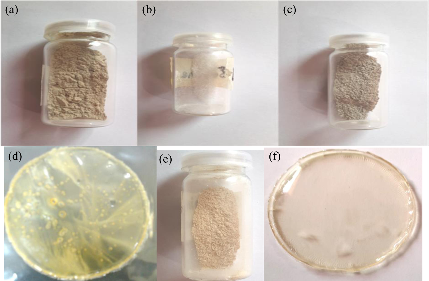
Photographic images of (a) bentonite, (b)
Preparation of PS
Ten grams of styrene monomer was poured into a 250 mL round bottom flask. Then, 0.1 g SDS (anionic surfactant) was added to the flask and 60 mL deionized water was also added to the mixture. The mixture was sonicated for 0.1 h. Afterward, 0.03 g ammonium persulfate initiator was added to the mixture. Finally, the mixture was refluxed for 6 h at 80°C. 24 The jelly-like yellow product obtained was poured in a petri dish and dried at room temperature for 24 h. After drying, pale yellow-colored PS was obtained.
PS film formation
One gram of the above prepared PS was dissolved in 10 mL THF with continuous stirring for 2 h. The resulting mixture was poured into a glass petri dish and left at room temperature for 6 h under vacuum. Finally, a transparent PS film was obtained. 25
Preparation of PA
HDA 1.162 g and TPC 2.03 g were dispersed in 50 mL DMSO. The mixture was refluxed at 120°C for 6 h. After cooling the mixture to room temperature, it was poured into 500 mL distilled water. The color of resulting solution was orange yellow. 26 Then, the mixture was filtered and the residue was dried at 70°C for 4 h. Finally, a yellow residue of PA was obtained.
Preparation of polystyrene/bentonite (PS/M-Bet) nanocomposite film
Initially, 1 g PS was dissolved in 10 mL THF with continuous stirring for 2 h. Then, the desired content of organomodified bentonite clay was added (0.01 g, 0.03 g, 0.05 g, 0.1 g, and 0.5 g) to the mixture and stirred for 12 h to achieve exfoliation of the nanoclay. Finally, it was poured into a glass petri dish and dried at room temperature for 24 h under vacuum (Figure 3).
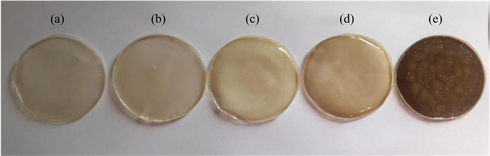
Photographic images of (a) PS/M-Bet 0.01, (b) PS/M-Bet 0.03, (c) PS/M-Bet 0.05, (d) PS/M-Bet 0.1, and (e) PS/M-Bet 0.5 nanocomposite films. PS: polystyrene; M-Bet: modified bentonite.
Preparation of polyamide/bentonite (PA/M-Bet) nanocomposite
One gram of PA was dissolved in 10 mL DMSO by stirring for 30 min. Then, 0.01 g organomodified bentonite was added to the mixture and further stirred for 24 h. Afterward, the mixture was poured into a glass petri dish and dried at 120°C (4 h). 27 Light brown color flakes of PA/bentonite composite were obtained (Figure 4). The experiment was repeated with 0.03 g, 0.05 g, 0.1 g, and 0.5 g of organomodified bentonite as nanofiller.
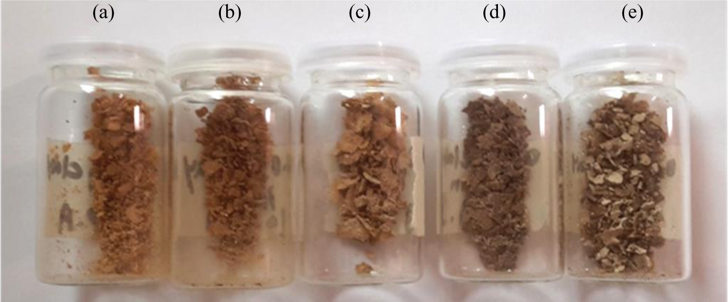
Photographic images of (a) PA/M-Bet 0.01, (b) PA/M-Bet 0.03, (c) PA/M-Bet 0.05, (d) PA/M-Bet 0.1, and (e) PA/M-Bet 0.5 nanocomposite. PA: polyamide; M-Bet: modified bentonite.
Preparation of PS/PA blend film
One gram of PS was dissolved in 10 mL THF by stirring for 2 h. To the mixture, 0.01 g PA was added and continuously stirred for 24 h. The possible interaction between the polymers is shown in Figure 5. Finally, the mixture was poured into a petri dish and dried at room temperature for 24 h. A smooth opaque film was obtained.
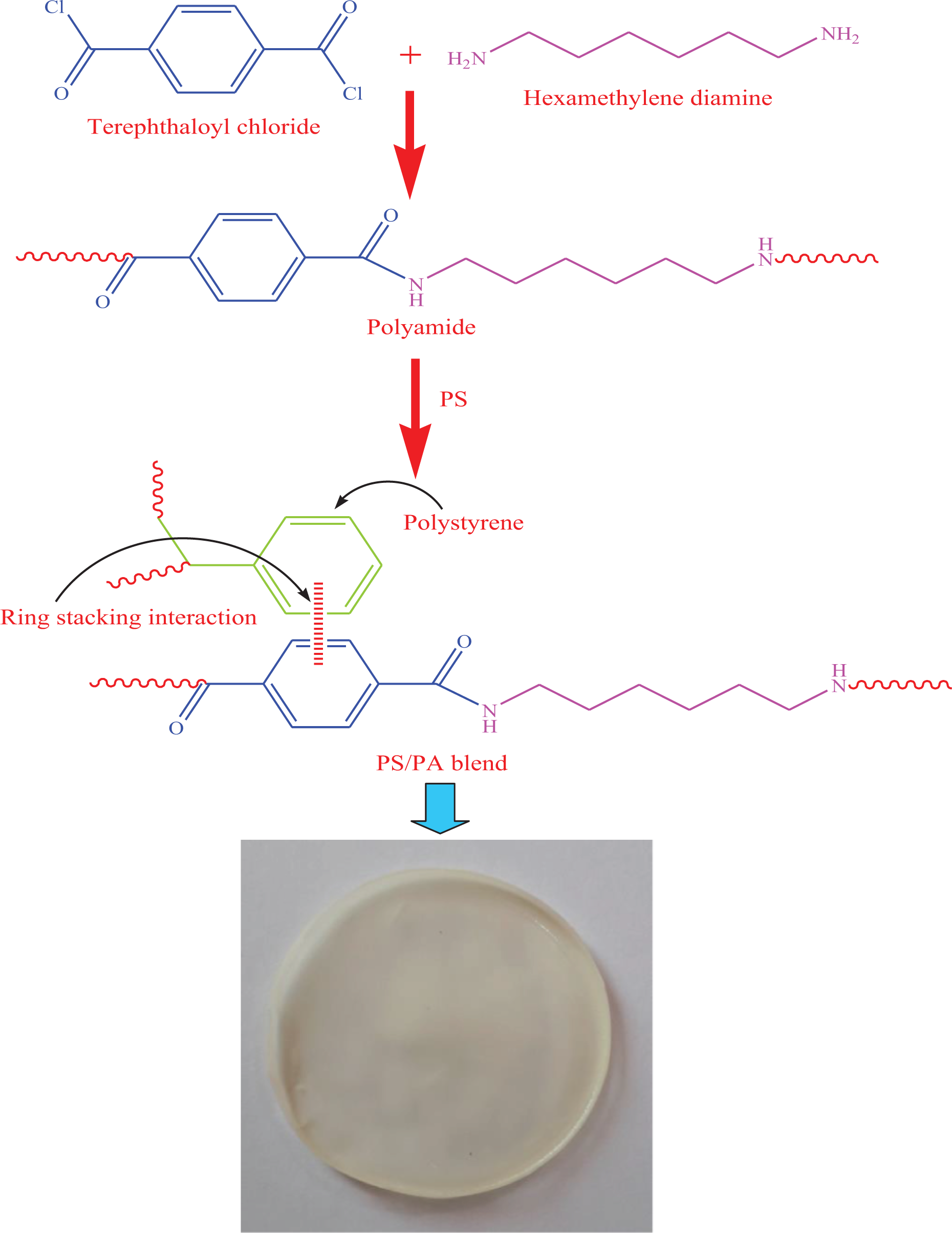
Formation of PS/PA blend. PS: polystyrene; PA: polyamide.
Preparation of PS/PA/organomodified bentonite (PS/PA/M-Bet) nanocomposite film
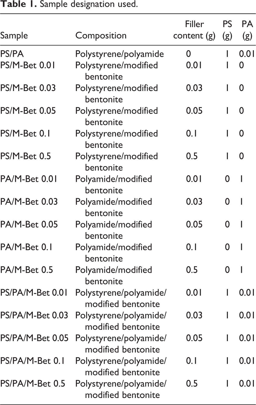
PS 1 g and PA 0.01 g were dissolved in 10 mL THF and stirred for 2 h to form a homogeneous mixture. Then, a desired amount of organomodified bentonite clay (0.01, 0.03 g, 0.05 g, 0.1 g and 0.5 g) was added to the mixture and stirred for 12 h. Finally, the mixture was poured into a glass petri dish and dried at room temperature for 24 h. The PS/PA blend and bentonite nanocomposite films obtained are shown in Figure 6. The interaction between PS/PA blend and M-Bet is shown in Figure 7. The sample designation used in this study is given in Table 1.

Photographic images of (a) PS/PA/M-Bet 0.01, (b) PS/PA/M-Bet 0.03, (c) PS/PA/Bet 0.05, (d) PS/PA/M-Bet 0.1, and (e) PS/PA/M-Bet 0.5 nanocomposite. PS: polystyrene; PA: polyamide; M-Bet: modified bentonite.

Interaction of PS/PA blend and modified bentonite nanocomposite. PS: polystyrene; PA: polyamide.
Sample designation used.
Results and discussion
Spectral analysis
The structure of the modified M-Bet was studied using FTIR. The spectrum of the organomodified bentonite clay is shown in Figure 8(a). The broad absorption peak at 3615 cm−1 represents the characteristic hydroxyl group stretching vibration of Mg–OH–Al, Al–OH–Al, and Fe–OH–Al units of nanoclay octahedral layer. The peaks at 1631 and 1519 cm−1 appeared due to the hydroxyl group bending vibrations of entrapped water molecules. The O–Si–O asymmetric stretching mode was detected at 1006 cm−1. The peaks at 531 and 628 cm−1 were assigned to Si–O bending vibrations. Moreover, Al–O–Si bending vibration was observed at 573 cm−1, while Si–O–Si bending vibration was observed at 433 cm−1. 28 Figure 8(b) shows the FTIR spectrum of PA. The characteristic absorption peak at 3426 cm−1 was attributed to amide N–H stretching vibration. The amide N–H bending vibration was also observed at 1576 cm−1. The peaks at 3064, 2928, and 2881 cm−1 were attributed to aromatic and aliphatic sp3 C−H stretching vibrations, respectively. The C–N stretching vibration of PA backbone was observed at 1408 cm−1. Moreover, the amide carbonyl C=O stretching vibration was observed at 1675 cm−1. Presence of aromatic C=C stretching vibration was observed at 1506 cm−1. Moreover, the peak at 1281 cm−1 indicated the C–O bond stretch. The characteristic C–H bending of aromatic ring also appeared at 720 cm−1. Figure 8(c) shows the FTIR spectrum of PS/M-Bet 0.05 nanocomposite. The spectrum of PS/M-Bet nanocomposite depicts peaks both due to organomodified bentonite and PS structure. The peaks around 3605 and 1685 cm−1 were observed due to stretching and bending vibrations of hydroxyl groups of bentonite clay. Lowering of hydroxyl group stretching vibration showed that the bentonite layers were intercalated with the polymer matrix. The stretching vibrations of aromatic and aliphatic C–H groups appeared at 3019and 2914 cm−1, respectively. These peaks were also observed in the PA spectrum. The nanocomposite also exhibits peak at 1604 cm−1 due to aromatic C=C functionality. The peaks at 1499 and 1442 cm−1 appeared due to C–N stretch, while peaks at 757 and 688 cm−1 were due to aromatic C–H bending vibrations. In addition, the nanocomposites demonstrate characteristic peak of Si–O at 1025 cm−1. The low frequency peak at 526 cm−1 shows Si–O bending vibrations, while the peak at 432 cm−1 corresponds to Si–O–Si bending. The spectrum of PS/PA/M-Bet 0.05 nanocomposite is shown in Figure 8(d). The characteristic amide N–H stretching vibration appeared at lower wave number (3385 cm−1) due to hydrogen bonding. The absorption peaks at 3022 and 2923 cm−1 were assigned to aromatic and aliphatic C–H stretching vibrations. The amide carbonyl also appeared at lower wave number (1646 cm−1) due to hydrogen bonding. Furthermore, PS/PA/M-Bet 0.05 nanocomposite showed lowering of aromatic C=C stretch at 1501 cm−1 due to ring stacking interaction (π–π) between PS and PA. The peak at 1450 cm−1 indicates the C–N stretching vibration of PA. The adjacent peaks corresponding to aromatic C–H bending vibrations also appeared at 692 and 762 cm−1. Moreover, the nanocomposite shows Si−O stretching vibration at 1029 cm−1. This proves that the bentonite layers were intercalated in the blend matrix. The peak at 537 cm−1 corresponds to Si−O bend, whereas peak at 481 cm−1 corresponds to Si–O–Si bending vibrations. The spectral assignments have established that the M-Bet layers have been intercalated with the matrix to form PS/M-Bet nanocomposite.
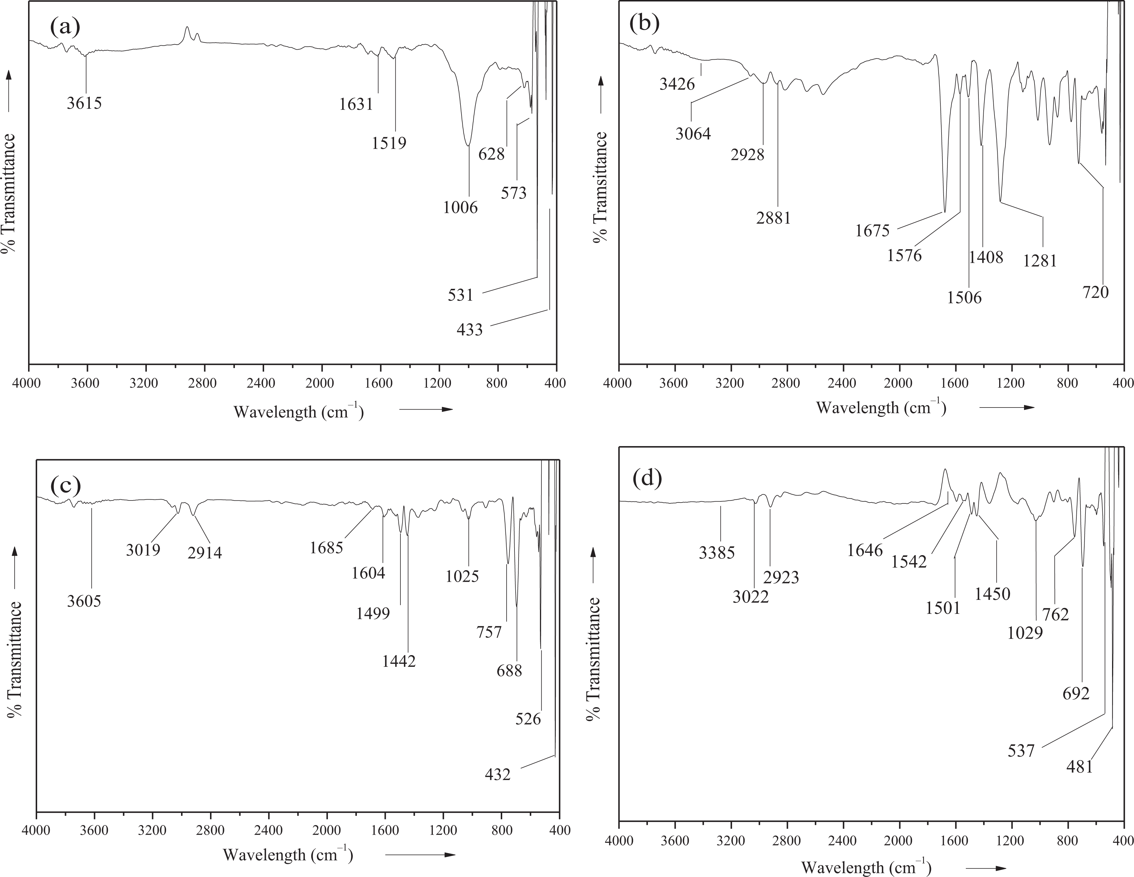
FTIR spectra of (a) M-Bet, (b) PA, (c) PS/M-Bet 0.05, and (d) PS/PA/M-Bet 0.05. PS: polystyrene; PA: polyamide; M-Bet: modified bentonite.
Microstructure analysis
Morphological studies were performed using FE-SEM. The nanoclay dispersion in the polymer matrix is a vital feature for nanocomposite performance. The influence of organomodified bentonite clay on morphology was analyzed in various samples. In PA/M-Bet 0.05, polymer-coated bentonite flakes were seemed to be dispersed in the matrix (Figure 9). A fine dispersion pattern was observed. At higher resolution, large flakes appear like an array of paper pieces (Figure 9(b)). The distinctive flat appearance suggests that the polymerization process occurs inside the clay galleries. Polymerization is then continued outside the nanoclay platelets. Consequently, the size of clay particles decreases and interparticle distance increases leading to a flake-like arrangement of nanoclay particles in the PA matrix. However, small nanoclay particles were seemed to be embedded in the matrix. Fine agglomerates were observed in the matrix with the addition of 0.5 g nanoclay loading in PA/M-Bet 0.5 (Figure 9(c) and (d)). Since bentonite clay loading was high, it led to a reduction in space for nanoplatelet to exfoliate completely. Figure 9(e) and (f) shows micrographs of PS/M-Bet 0.05. The dispersion of clay tactoids was not uniform. The micrometric clay aggregates were observed, which were not dispersed. It was found that the lesser amount of M-Bet (0.05 g) nanoclay particles was not well dispersed in the matrix. Similarly, large aggregates were also seen in the micrographs of PS/M-Bet 0.5 (Figure 10(a) and (b)). Nonhomogenous distribution of bentonite indicated that there was no fine adhesion between the matrix and nanoclay. However, the dispersion of bentonite microparticle domain in PS phase was uniform compared with the 0.05 g loaded composite. The properties of two-phase polymer blend/clay nanocomposite were found to be dependent on the morphology of nanoclay. 29 The morphology of PS/PA/M-Bet 0.5 is shown in Figure 10(c) to (f). A unique morphology was observed for lower organomodified clay content. The matrix was arranged in the form of honeycomb-like structure. The nanoclay particles were clearly trapped within the matrix strands due to the interaction between the nanofiller and the PA chains. The unique honeycomb pattern morphology of PS/PA/M-Bet appears to be co-continuous in nature. This sort of morphology is unique in the case of polymer/clay nanocomposite. The effect of morphology on flame retardancy has previously been discussed in the literature. 30,31 The polymer/nanoclay nanocomposites have been found to exhibit peak heat release rate (PHRR) reduction, if nanomorphology is achieved through exfoliation and intercalation. In the case of PS/PA/M-Bet nanocomposite, the difference in nanomorphology with nanoclay loading also significantly affected the flame retardancy of materials, as discussed in Nonflammability investigation section. The nanocomposites were obtained by organomodifying nanoclay and dispersion was achieved through solution mixing. Consequently, the organomodified nanoclay surface was not degraded at high temperature, causing organomodification during solution mixing and increasing the nanocomposite flame retardancy.
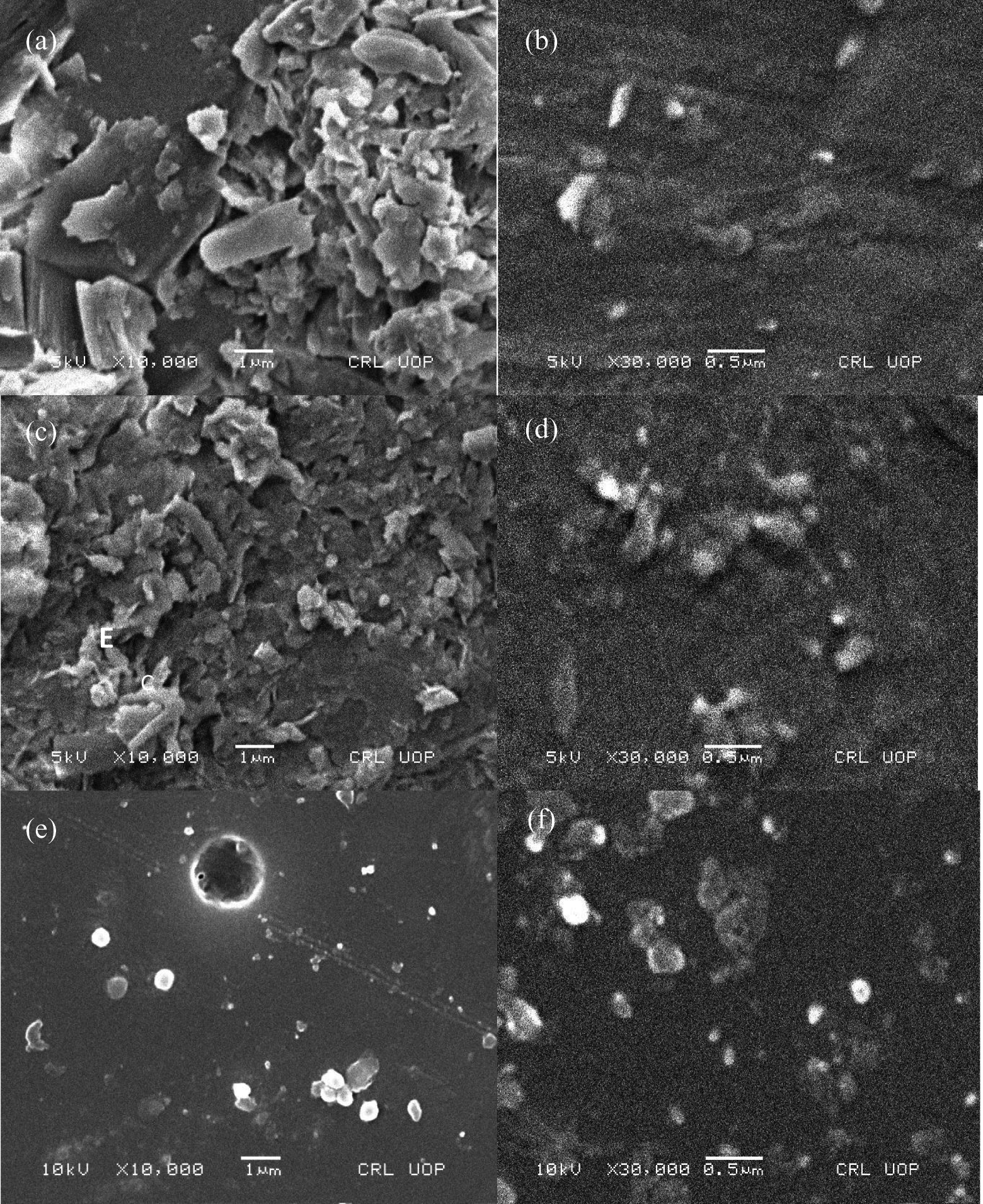
SEM images of (a and b) PA/M-Bet 0.05; (c and d) PA/M-Bet 0.5; and (e and f) PS/M-Bet 0.05. PA: polyamide; M-Bet: modified bentonite.
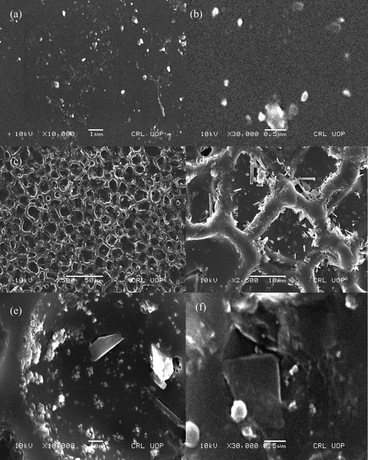
FE-SEM images of (a and b) PS/M-Bet 0.5 and (c-f) PS/PA/M-Bet 0.5. PS: polystyrene; PA: polyamide; M-Bet: modified bentonite.
XRD study
XRD analysis was used to study the microstructure of organoclay, polymer, and nanocomposite. The studies were performed with a scattering angle θ ranging from 0° to 50°. Figure 11 (A) shows the diffraction patterns of organomodified bentonite and PA. An intense peak was observed at 2θ = 5.7°, which is an indication of clay modification in organomodified bentonite. The pattern also shows small peaks of low intensity, indicating the presence of nanoclay Na-Mg-Al-Si4O11 crystals. After the inclusion of the intercalating agent, an increase in the basal spacing (d 001) of the modified clay was observed. The diffraction pattern of PA (Figure 11(B)) shows characteristic peaks of 2θ = 15.5°, 17.2°, 24.8°, and 27.2° due to semicrystalline nature of the polymer. Figure 11 (C and D) shows diffractograms for PA/M-Bet 0.05 and PA/M-Bet 0.5, respectively. Both nanocomposites revealed common peaks of 2θ = 17.2°, 25°, 27.7°, and 29.6° corresponding to the polymers. A high-intensity peak of 2θ =17.2° was observed for both PA/M-Bet 0.1 and PA/M-Bet 0.5. The PA molecular chains seem to intercalate in intergallery spaces of organomodified bentonite and further exfoliate the organomodified layered silicates. The small peaks in the diffractogram show the presence of organomodified bentonite crystals. Moreover, the peak for organomodified bentonite was lowered to 2θ = 4.41° in PA/M-Bet 0.05 nanocomposite. With 0.5 g bentonite loading, the peaks were further shifted to 2θ = 4.22°. The shift indicates that the basal spacing of the organoclay was increased due to polymer intercalation. 32 Similarly, an increase in basal spacing was observed in the case of PS/M-Bet nanocomposite (Figure 11 (E and F)). The organoclay peak was experiential at 2θ = 4.94° (PS/M-Bet 0.05) and 2θ = 4.59° (PS/M-Bet 0.5). Both of the PS/bentonite composites show common peaks at 2θ = 12.3° and 24.9°. The presence of small peaks suggests the occurrence of organomodified bentonite crystals.
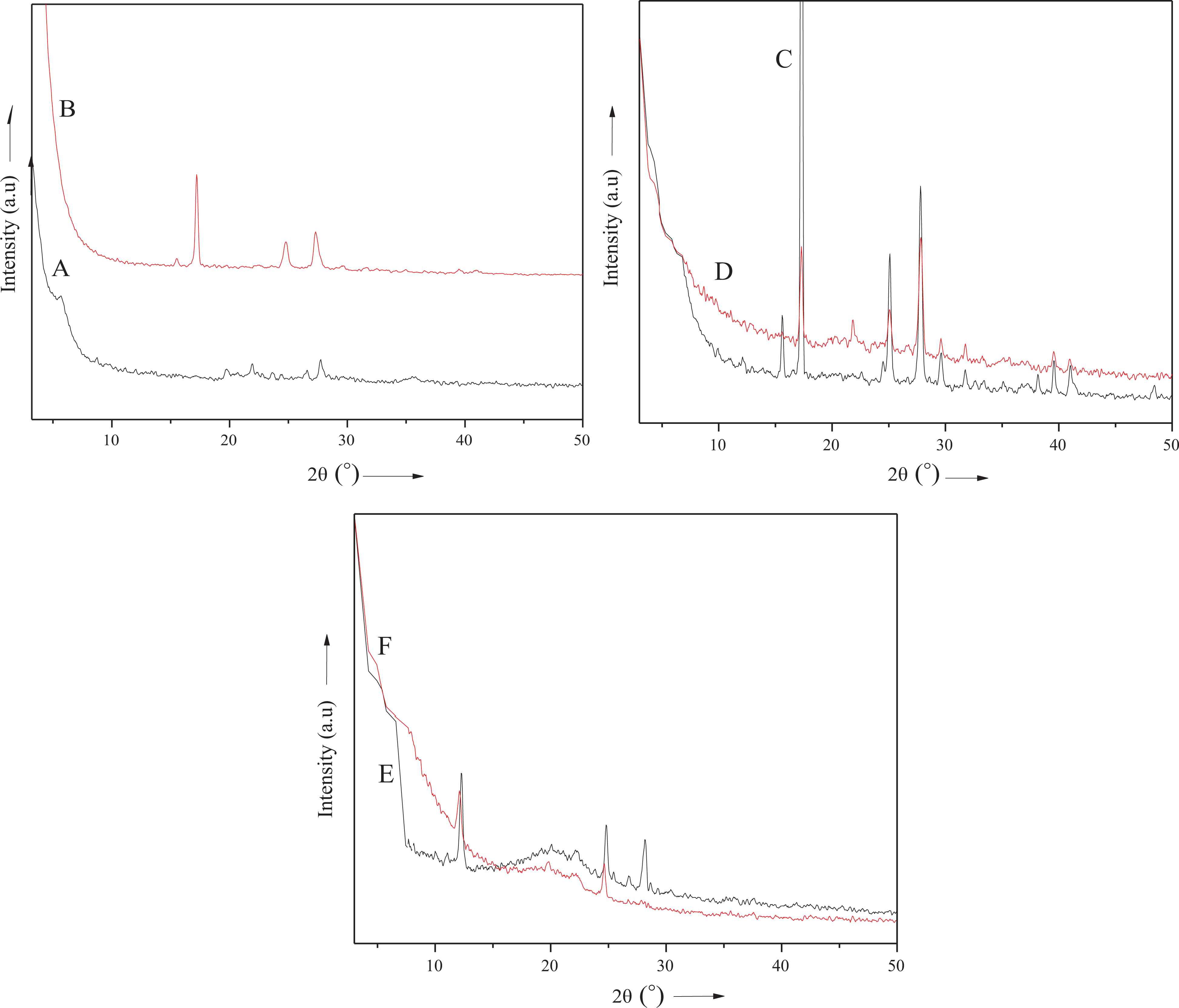
XRD patterns of (A) PA, (B) M-Bet, (C) PA/M-Bet 0.05, (D) PA/M-Bet 0.5, (E) PS/M-Bet 0.05, and (F) PS/M-Bet 0.5. PA: polyamide; M-Bet: modified bentonite.
Thermal analysis
Thermal properties of the nanocomposite series were analyzed using TGA, differential thermogravimetric analysis, and DSC techniques. The effect of bentonite nanoclay loading on PS, PA, and PS/PA blend was studied by determining T 0, T max, and T g. T max was obtained from DTG curves. The corresponding values of T 0, T max, and T g of nanocomposites are listed in Table 2. Thermogravimetric analysis was performed in the temperature range of 35–700°C at a heating rate of 10°C min−1 (N2 atmosphere). TGA analysis of PS/M-Bet 0.01 nanocomposite revealed T 0 and T max of 261°C and 333°C, respectively. The degradation temperature was increased with the nanofiller loading, so PS/M-Bet 0.05 nanocomposite showed T 0 and T max of 284°C and 343°C, respectively; 0.5 g loaded nanocomposite showed higher values of T 0 and T max (290°C and 358°C) in this series (Figure 12 (A and B)). Thermal stability of PA and bentonite series was found to be higher than the PS series. PA/M-Bet 0.01–0.5 revealed T 0 and T max in the range of 291–308°C and 360–398°C, respectively. DTG thermograms of PA-bentonite nanocomposite are shown in Figure 12 (C and D). At high bentonite content, exfoliation was dominated to promote improvement in the thermal stability of PA. In other words, enhanced thermal stability may lead to high performance of the resulting nanocomposite at an elevated temperature. 33 Similar to PA/M-Bet nanocomposite, the thermal stability of PS/PA blend-bentonite nanocomposite was also improved with higher bentonite content (Figure 12 (E and F)). T 0 and T max for PS/PA/M-Bet 0.5 nanocomposite were recorded as 321°C and 400°C, respectively. The blend sample with 0.5 g nanoclay loading depicted higher thermal stability among all the nanocomposite series studied. The improved heat resistance was due to the formation of a stable structure because of the fine interaction between the blend components and nanoclay platelets.
Thermal data of PS/M-Bet, PA/M-Bet, and PS/PA/M-Bet nanocomposite.

T 0: initial decomposition temperature; T max: maximum weight loss temperature; Tg : glass transition temperature. PS: polystyrene; PA: polyamide; M-Bet: modified bentonite.
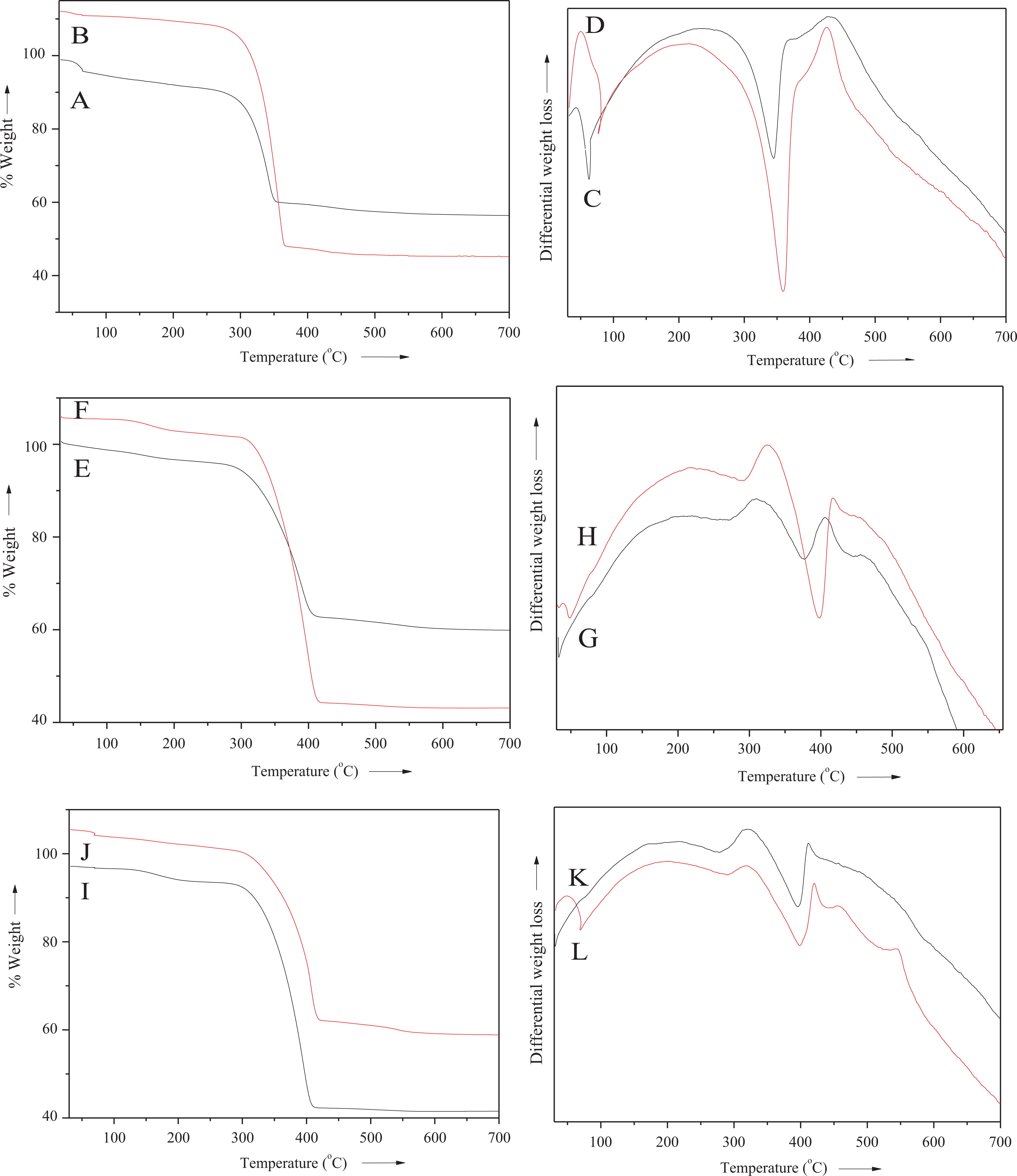
TGA/DTA thermograms of (A and C) PS/M-Bet 0.05, (B and D) PA/M-Bet 0.5, (E and G) PS/M-Bet 0.05, (F and H) PA/M-Bet 0.5, (I and J) PS/PA/M-Bet 0.05, and (K and L) PS/PA/M-Bet 0.5 nanocomposite. TGA: thermogravimetric analysis; DTA: differential thermogravimetric analysis; PS: polystyrene; PA: polyamide; M-Bet: modified bentonite.
Nanoclay loading also enhanced the Tg of nanocomposite series. PS/M-Bet 0.01–0.5 showed Tg of 229–343°C, PA/M-Bet 0.01–0.5 had Tg = 340–349°C, while PS/PA/M-Bet 0.05 showed Tg in the range of 351–385°C. As shown in Figure 13, all the nanocomposites revealed a single glass transition point. In addition, Tg was found to increase with the nanoclay loading. Usually, nanofiller influences Tg of polymer matrices by two contradictory effects: (i) decrease in chain mobility due to interaction with rigid nanofiller and (ii) increase in free volume due to the presence of nanofiller, which may loosen the molecular chain packing. Here, the increase in Tg was due to restricted segmental motion of the polymer chains occurring at the organic–inorganic boundary. Therefore, the increase in Tg was observed owing to the confinement of polymer chains between the silicate galleries. 34
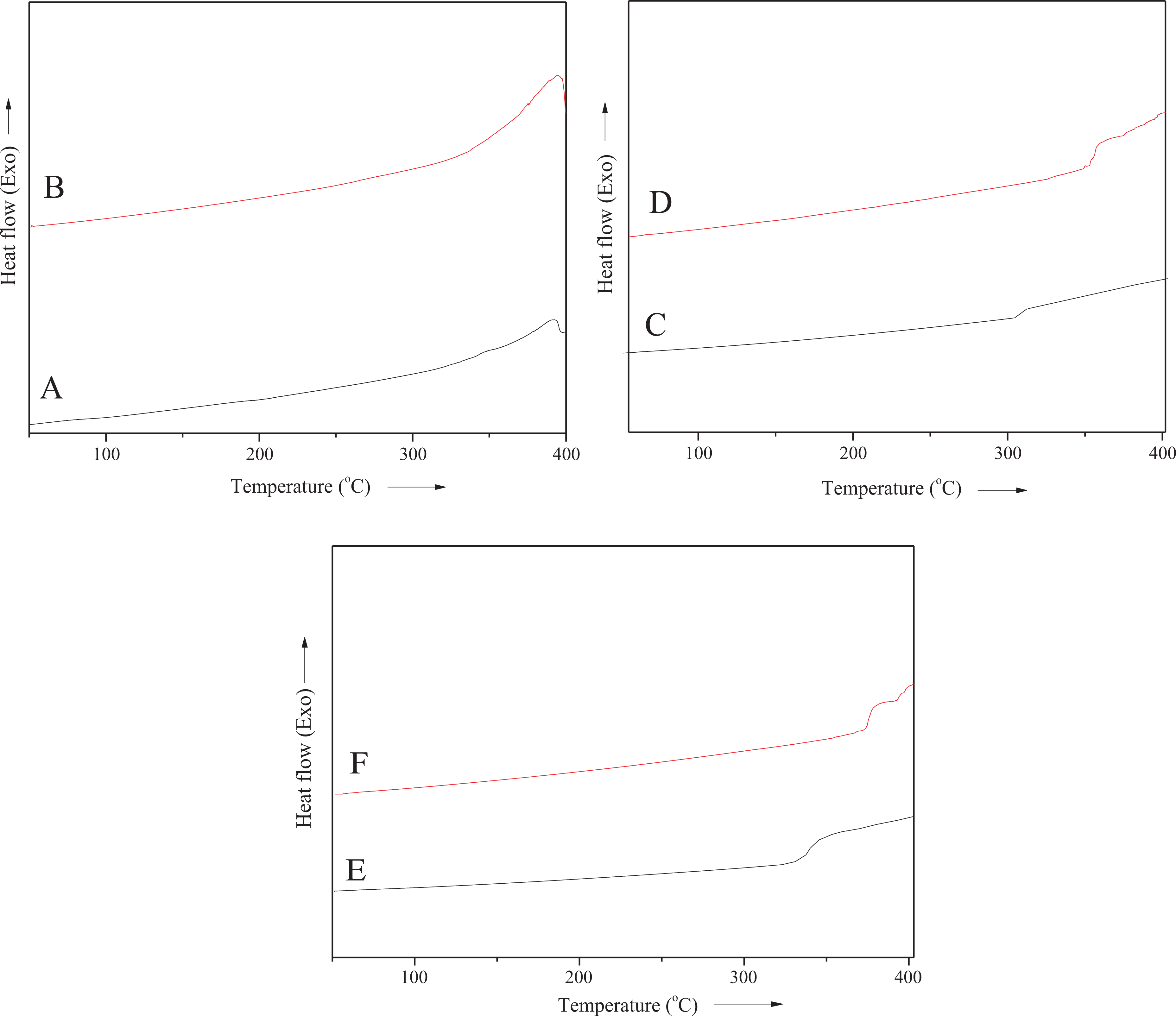
DSC thermograms of (A) PS/M-Bet 0.05; (B) PS/M-Bet 0.5; (C) PA/M-Bet 0.05; (D) PA/M-Bet 0.5; (E) PS/PA/M-Bet 0.05; and (F) PS/PA//M-Bet 0.5 nanocomposite. PS: polystyrene; PA: polyamide; M-Bet: modified bentonite.
Nonflammability investigation
In order to examine the flame retardancy of nanocomposite, cone calorimetric technique was used (Table 3). For neat PS/PA blend, the maximum PHRR and the time to achieve PHHR were found to be 411 kW m−2 and 210 s, respectively. In PS/M-Bet 0.05 nanocomposite, the PHRR was significantly decreased to 240 kW m−2 in 154 s. The addition of 0.5 g M-Bet to the PS matrix further decreased the PHHR to 210 kW m−2 in 143 s. Effect of clay addition was also observed in the PA/M-Bet nanocomposite. The PHRR was 176 kW m−2 for PA/M-Bet 0.5 nanocomposite, that is, lower than the PA/M-Bet 0.05 nanocomposite (200 kW m−2). In nanocomposite and blend systems, increasing nanoclay content up to 0.5 g decreased the PHRR to 145 kW m−2 in 102 s. There was 65% decrease in flammability of the nanocomposite compared with the PS/PA blend (Figure 14). The heat release rate of nanocomposite during combustion indicated that the nanoclay particles have significantly reduced the combustion process. Therefore, PS/PA/M-Bet nanocomposite has better flame retardancy than the blend and other composite series. The time to achieve PHRR was also reduced considerably with the nanofiller addition in the matrix. The nonflammability of novel nanocomposite was found to be better than the reported polymer/clay materials. 35 PS, PA, blend, and bentonite nanocomposites have unique structure to be employed as flame-retardant materials. Nanoclay-based flame retardants have revealed high flame-retardant efficiencies. The flame retardancy mechanism of these nanocomposites can be related to the nanoclay structure as well as the polymer design. The natural bentonite clay surface is hydrophilic; consequently, the nanoclay easily disperses in aqueous solutions but not in polymers. Therefore, bentonite nanoclay was modified using organic cations such as amino acid forming hydrophobic organomodified clays that can be readily dispersed in polymers. PHRR and time to achieve PHRR are the important parameters in cone calorimetry to characterize the material flammability. PHRR is the most important parameter used to describe flammability and is assumed as the driving force of the fire. Adding only a small amount (i.e. 0.01–0.5 wt%) reduced the PHRR of polymers and thus decreased the speed at which flame spread throughout them. Inclusion of nanoclay, thus, reduced the PHRR, that is, the combustion heat intensity. Moreover, such small amount of nanoclay did not reduce polymer processability and improved the thermal properties of polymers. The addition of nanoclay also produced self-extinguishing V-0 nanocomposite that is required for fire-retardant products. However, the technology used to produce reliable flame-retardant nanocomposite requires further studies.
Cone calorimetery data for nanocomposite.

PHRR: peak heat release rate; PS: polystyrene; PA: polyamide; M-Bet: modified bentonite.
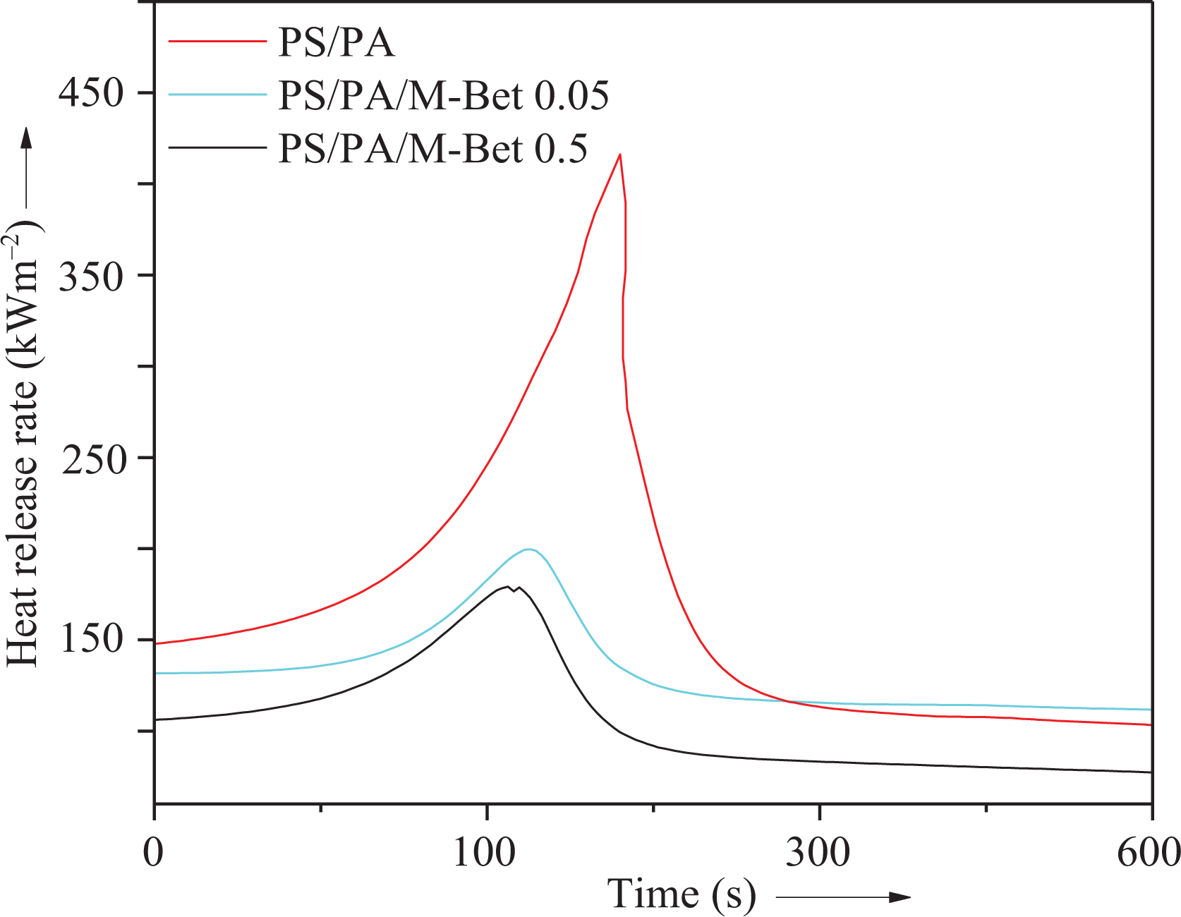
Dependence of heat release rate on time for PS/PA/M-Bet nanocomposite. PS: polystyrene; PA: polyamide; M-Bet: modified bentonite.
Conclusion
In this research work, nanocomposite of PA and PS was prepared using organomodified bentonite nanoclay and exfoliation method. The bentonite nanoclay was organomodified using a novel approach to intercalate with
Footnotes
Declaration of conflicting interests
The author(s) declared no potential conflicts of interest with respect to the research, authorship, and/or publication of this article.
Funding
The author(s) received no financial support for the research, authorship, and/or publication of this article.