
Abstract
Background
Smartphone-based 2D-pose estimation offers a convenient method for assessing shoulder range-of-motion (ROM), but its accuracy compared to 3D motion capture (3D-mocap) needs to be determined.
Methods
Shoulder ROM was recorded in seventeen participants without shoulder issues using 3D-mocap and 2D-pose concurrently. Movements included abduction, flexion, extension, external, and functional internal rotation (IR). 2D-pose ROM estimates (mymobility's® Skeletal Tracking Shoulder Range of Motion Assessments feature (Apple Vision framework, Apple Inc., Cupertino, CA, USA) were compared to 3D-mocap using linear mixed-models and Bland-Altman analysis. The influence of thoracic compensation and anatomical frame definitions on shoulder ROM estimates was examined.
Results
High consistency was observed between 2D-pose and 3D-mocap (R2 > 0.98), especially for abduction and flexion. Differences in ROM were linked to anatomical frame variations and thoracic contributions, with 2D-pose overestimating ROM at greater ranges (2°–25°). Internal rotation zone identification showed high consistency, but 2D-pose-based extension and external rotation showed more variability due to thoracic compensation.
Conclusions
Smartphone-based 2D-pose estimation provides a valid alternative for shoulder ROM measurement but should not be used interchangeably with 3D-mocap due to discrepancies arising from anatomical frame definitions and thoracic movements. Shoulder ROM assessment requires consideration of these limitations to ensure appropriate clinical interpretation.
Introduction
Objective assessment of functional shoulder range of motion (ROM) plays a crucial role in evaluating interventions aimed at enhancing overall shoulder function. 1 For example, measuring shoulder ROM after surgery can personalise patient care by identifying individuals with lower-than-expected shoulder ROM. In clinical practice, clinicians commonly assess functional shoulder ROM using a universal goniometer 2 or by estimating it through visual observation. 3 However, the moderate repeatability 4 and inter-tester reliability of these methods5–7 mean that any observed change in shoulder ROM over time may not necessarily reflect improvements or deterioration in shoulder function. Therefore, there is a need for more objective methods that are easy for clinicians to use and suitable for home-based measurements by patients. Recent advancements in 2D-pose estimation using a single smartphone camera offer a promising solution for this. However, there is limited comparison between this approach and established 3D-motion capture (3D-mocap) methods. 8
Markerless pose detection methods have gained popularity for assessing shoulder joint movements.9–12 For instance, data from camera-based Microsoft Kinect Azure indicates high correlations and minimal bias between Kinect and 3D-mocap-based functional shoulder ROM including abduction, flexion, external rotation, and internal rotation. 10 However, while Microsoft Kinect automatically detects body landmarks in 3D using both RGB cameras and a depth sensor, it requires an external PC for data processing. This could potentially limit its use on a larger scale, especially for home-based assessments. Alternatively, single smartphone camera-based 2D-pose detection offers a promising alternative that could be more accessible and convenient for users, making it an ideal choice for broader applications.
The Apple Vision framework 13 allows real-time detection of critical body landmarks through a machine-learning model. This pose estimation model enables automatic measurement of functional shoulder ROM from smartphone video recordings. Integrated into the mymobility® care management platform by Zimmer Biomet (Warsaw, IN, USA), this method, known as Skeletal Tracking Shoulder Range of Motion Assessments, quantifies shoulder angle by assessing the relative angle between the upper arm and thorax segments. This approach provides an approximation of thoracohumeral ROM. Our preliminary findings indicate a consistent relationship with 3D-mocap thoracohumeral shoulder ROM using recommendations from the International Society of Biomechanics (ISB); however, some bias was observed. 8 This bias likely stems from the suboptimal definition of the thorax reference frame in certain shoulder movement types.8,14 Addressing this bias requires an improved definition of the thorax segment reference frame. Furthermore, expanding the assessment to include other shoulder movements such as internal and external rotations, as well as functional internal rotation (i.e. with hand behind the back), is important for clinical use. This expansion requires time-series data to fill in previously unassessed active shoulder ranges, 8 enabling a more comprehensive comparison of the full active ROM range for all clinical shoulder movement assessments.
Most 2D-pose methods define the thorax as the line connecting the hip and shoulder joints. Scarcity of spine markers in between the hip and shoulder hinders accurate orientation estimation of the thorax segment, and relative spine movement could inadvertently influence active shoulder range, leading to overestimation of shoulder function. This information is crucial because compensations from other segments to active shoulder ROM are to be expected in clinical populations. Therefore, it is critical to determine whether differences between 2D-pose and 3D-mocap-based shoulder ROM are related to these thoracic compensations.
3D-mocap is often considered the gold standard but has limitations. To check its impact on 2D-pose versus 3D-mocap, we also used the 2D-view (from phone camera perspective) from 3D-mocap, broadening the comparison and potentially accounting for Euler decomposition effects.
Therefore, the main aim of this study was to compare shoulder motions, in individuals with normal shoulder function, estimated using 2D-pose skeletal tracking against those derived from 3D-mocap and 2D-view from 3D-mocap in abduction, flexion, extension, external rotation (ER), and functional internal rotation. The secondary aim was to explore the relationship between thoracic compensation and the difference between 2D-pose and 3D-Mocap.
Methods
Participants
Seventeen individuals (mean (standard deviation): age 31 (7) years, height 1.72 (0.10) m, mass 68 (13) kg; 8 female, 9 male) with normal shoulder function were recruited from the local community via convenience sampling. Participants were excluded if they had a history of shoulder dislocation; reported perceptions of subluxation; reported pain suspected to originate from any intra-articular, tendon, or shoulder muscle injury (e.g. supraspinatus tendinopathy), pain following acute trauma, and other current musculoskeletal injury/pain > 2 on an 11-point numerical rating scale (NRS); had limited shoulder function or caused them to seek care within the previous 6 months; and are unable to understand written and spoken English or to provide informed consent.
Participants provided written informed consent, and all procedures were approved by the Institutional Human Ethics Committee (#2000000470).
Procedure
3D-motion capture setup
3D positions of reflective markers were recorded using an eight-camera Vicon Vero system using Nexus software (Figure 1, Nexus, v2.14.0.139696 h, Vicon Motion Systems, Ltd., Oxford, UK) at 60 samples/s. Pelvis, thorax, upper, and forearm were assumed to be rigid segments, and their positions and orientations were tracked using clusters (NaturalPoint Inc, Corvallis, OR, USA) with four non-collinear reflective markers (14 mm, Vicon Motion Systems Ltd., Oxford, UK), except for the forearm. They were attached to the sacrum, back at the level of the fifth thoracic vertebra, and the lateral upper arm approximately two-thirds the distance from the greater trochanter to the lateral humerus epicondyle using double-sided tape. To determine local anatomical coordinate systems according to ISB recommendations, 15 anatomical landmarks were identified using a custom pointer 16 and linked to the respective clusters. These were left and right posterior (SIPS) and anterior superior spines for the pelvis; C7, T8, sternal notch, and xiphoid for the thorax.15,17 The following reflective markers were attached: lateral humeral epicondyles, ulnar and radial styloid, and an additional marker positioned to the lateral aspect approximately one-third distance between the lateral epicondyle and radial styloid (Figure 1).
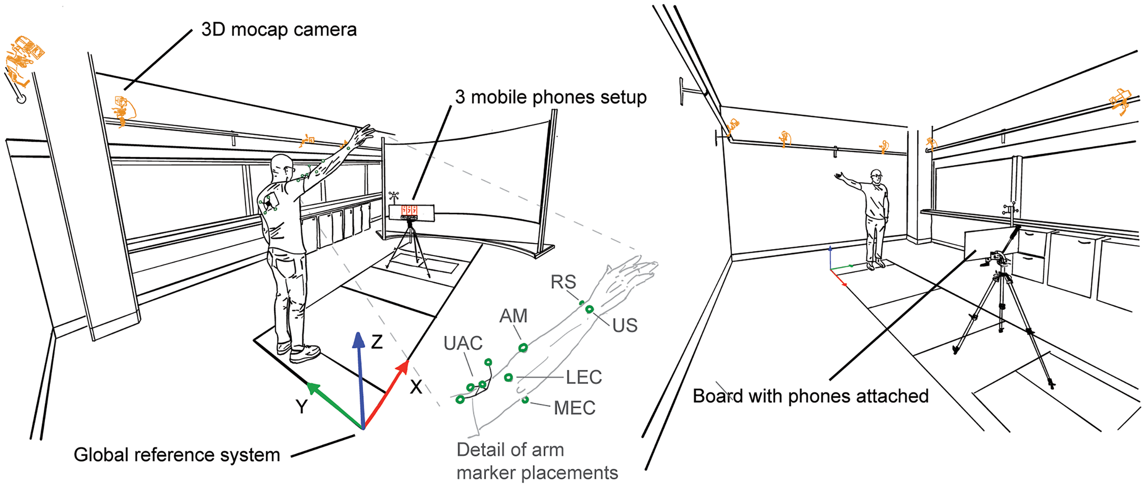
Measurement setup. Upper limb movements were concurrently recorded using three iPhones (mounted on a board, phones highlighted in red) and an eight-camera 3D-motion capture system (cameras highlighted in orange). Reflective markers are highlighted in green. The inset shows a detailed reflective marker setup of the arm. UAC: upper arm cluster; AM: additional marker; RS: radial styloid; US: ulnar styloid; LEC: lateral epicondyle; MEC: medial epicondyle. See 3D motion capture setup for more details.
The upper arm anatomical coordinate system also requires the glenohumeral joint position 15 which was estimated using a functional approach.18,19 To allow the recording of relative motion between the upper arm and scapula, i.e. the glenohumeral joint, another cluster with four non-collinear markers was temporarily attached to the skin covering the acromion. 20 Then, 60 s of arm circumduction motion at ∼30°s−1 with angles up to ∼45° was recorded. The circumduction movements of the upper arm were expressed in the scapula cluster axis system. The estimated coordinates of the glenohumeral joint were then expressed in the upper arm cluster axis system. After this procedure, the scapular cluster was removed. Participants wore a t-shirt with a cut-out to allow visibility of the thoracic marker cluster (see van den Hoorn et al. 8 for more details).
2D motion capture setup
Participants stood in front of three iPhones (2 × iPhone 13, 1× iPhone 13 Pro) mounted alongside a board (Figure 1). The phones’ orientations were aligned with the board and gravity to minimise projection errors. 8 To record the orientation of the iPhones and the positions of the front-facing camera with the 3D-motion capture, a cluster with four non-collinear markers was attached to the board. The corners of the board and the phone's front-facing camera positions were identified using a custom pointer 16 and linked to the board cluster.
The distance from the phone was adjusted for each individual participant to optimise screen real estate such that the participant's upper limb remained visible throughout the movements tested (1.86 (0.14) m). Participants then watched the instruction video provided by the mymobility® app prior to each movement task, in which the required movement and movement speed: ∼4 s from start to maximum ROM to starting position was shown. Participants were verbally instructed to perform three repetitions of full available ROM of shoulder abduction, flexion, extension, ER in position I (ERI, shoulder in neutral, elbow on side), and II (ERII, at 90° shoulder abduction), or functional internal rotation in a quasi-randomised order. ER movements were always recorded consecutively as additional forearm markers were attached for these movements (and were removed afterwards). Note that the first six participants did not perform the functional internal rotation. Participants faced the phones for abduction and ERI (faced positive X, with positive Y to the left and positive Z upwards in the lab space); faced sideways for flexion, extension, and ERII (faced positive or negative Y in the lab space depending on the tested arm side (∼50% left/right); and faced the opposite direction for functional internal rotation (faced negative X, with positive Y to the right and positive Z upwards in the lab space). Participants were instructed to maintain a 90° elbow and hand in thumb up position throughout the ERI and ERII movements. After each recording, 2D-pose shoulder ROM data were uploaded to a dedicated server and downloaded for further analysis. 2D-pose data were recorded at 30 samples/s using the mymobility® app (v3.7.0, Zimmer Biomet, Warsaw, IN, USA) and concurrently with 3D-mocap. This frame rate is sufficient for slow upperlimb movements at ∼1 full cycle/4 s (0.25 Hz). 21
Data analysis
3D positional marker data were bi-directionally low-pass filtered with a second-order Butterworth filter at 6.1564 Hz, 22 resulting in a fourth-order Butterworth filter with a 5 Hz cut-off frequency. 23 Anatomical landmarks were reconstructed from the marker clusters into the global coordinate system.
3D-mocap shoulder movements
Shoulder angle Cardan sequences.
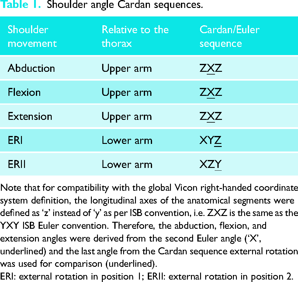
Note that for compatibility with the global Vicon right-handed coordinate system definition, the longitudinal axes of the anatomical segments were defined as ‘z’ instead of ‘y’ as per ISB convention, i.e. ZXZ is the same as the YXY ISB Euler convention. Therefore, the abduction, flexion, and extension angles were derived from the second Euler angle (‘X’, underlined) and the last angle from the Cardan sequence external rotation was used for comparison (underlined).
ERI: external rotation in position 1; ERII: external rotation in position 2.
As thorax movements can contribute to shoulder ROM in the volume, the thorax orientation relative to the volume was determined using YXZ Cardan decomposition. 15 Thorax orientation relative to the volume was extracted together with the shoulder ROM (see below).
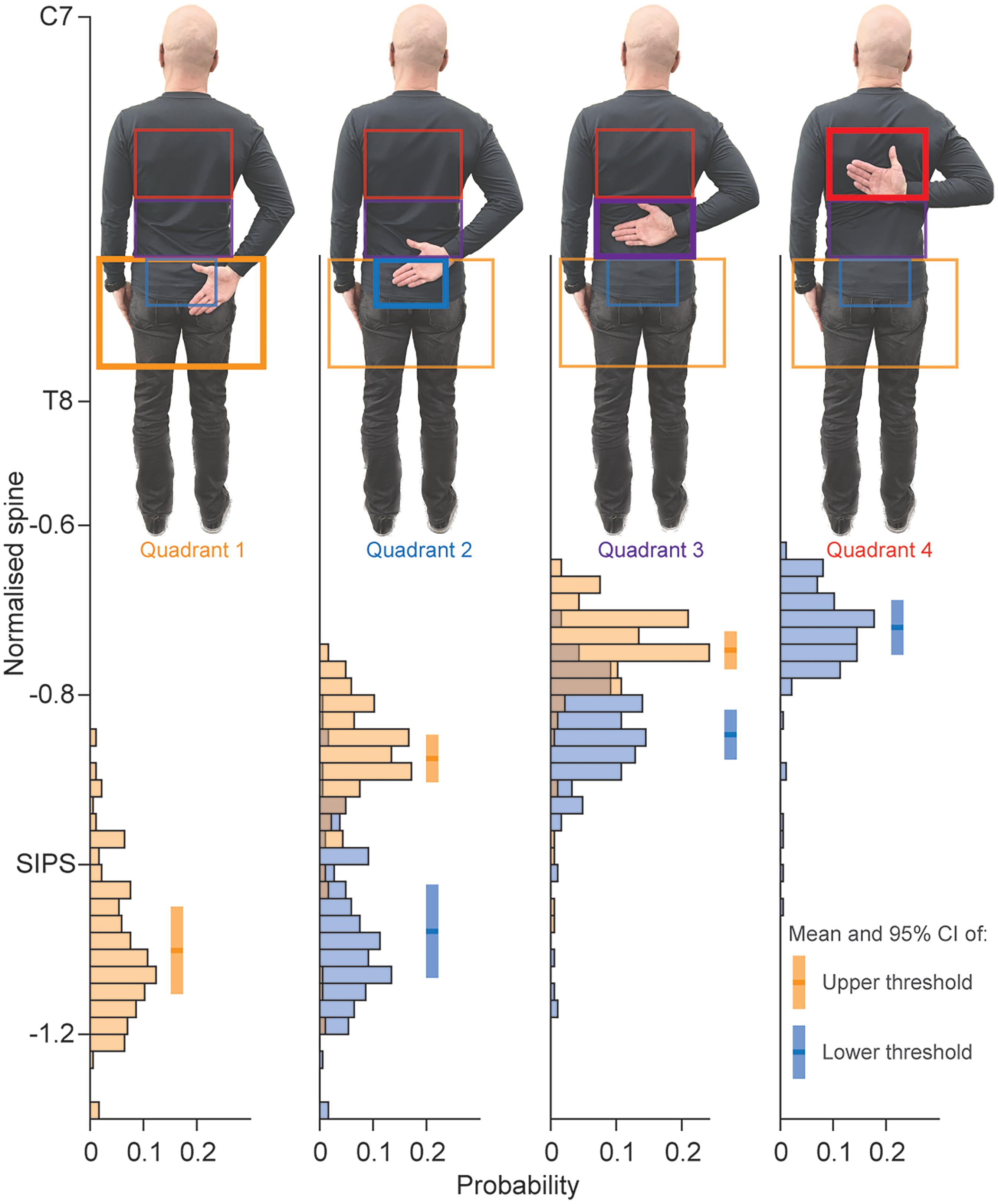
Functional internal rotation quadrant detection consistency. Distributions of the mean wrist position (3D-mocap) in terms of normalised spine height are displayed when a change in a quadrant was detected in 2D-pose. Distributions in orange reflect the upper threshold of a quadrant, and the distributions in blue reflect the lower thresholds of a quadrant. Note that quadrant 1 only has an upper threshold and quadrant 4 only has a lower threshold. C7: spinous process of seventh cervical spine; T8: spinous process of eighth thoracic spine; SIPS: posterior superior spines of the pelvis; CI: confidence interval.
The abduction, flexion, extension, and ERII shoulder angles were calculated by subtracting the upper-arm 2D-global z-axis angle from the 2D-global thorax z-axis angle using inverse tangents, similar to the calculation of the thoracohumeral shoulder angle on the phone (see below). For the ERI angle, the shoulder angle relied on the frontal projection of the lower arm onto the phone's 2D plane. For example, when the shoulder rotates externally to 90°, the entire length of the upper arm becomes visible. Conversely, when the shoulder rotates externally to 0°, the lower arm isn’t visible, indicating that the wrist and elbow positions coincide. The length of the lower arm was determined from the 3D mocap data as the length of the vector between the wrist (mean position of the ulnar and radial styloids) and the elbow (mean position of the lateral epicondyles of the humerus). The ERI angle was calculated as the inverse sine of the ratio of the 2D-projected distance between the elbow and wrist (
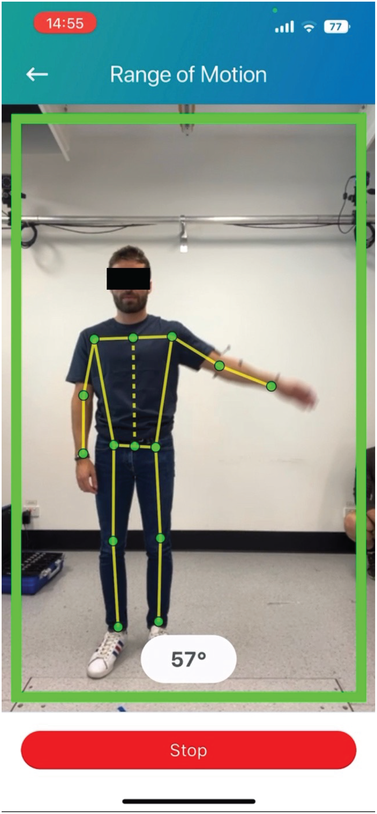
Example of 2D-pose landmark detection during shoulder abduction. The thorax is represented by the dashed yellow line between the bilateral hip and shoulder landmarks. The upper arm is represented by the line between the shoulder and elbow landmarks. Abduction is defined as the angle between these line segments. Note that estimated landmark positions are not displayed in the public version of the mymobility® app.
Some positional fluctuations in the 2D-pose estimated elbow and wrist landmarks were observed during the ERII movements, which resulted in ERII angle jumps. To compensate, the ERII 2D-pose-based angle was filtered using a 10th-order 1D median filter to remove the impact of these positional fluctuations. All other 2D-pose estimated shoulder angles were left unfiltered.
We applied the following data reduction. The three repetitions were divided into sections using the Vicon-based data. The start and end of each movement repetition were determined at the times when the shoulder angle velocity was >5°s−1 or <5°s−1, respectively, separated by the peak in shoulder angle. Using these time points, shoulder data were divided into increasing (start to peak velocity) and decreasing (peak velocity to end) sections. To further reduce the data, each section was divided into 12 sub-sections for abduction and flexion and 6 sub-sections for extension, ERI, and ERII. Within each sub-section, the mean angle derived from both systems was determined and used for further comparisons.
Statistics
All statistics were performed using Matlab (R2022b, MathWorks Inc., Natick, MA, USA). The significance threshold was set at p < 0.05. Performance of each of the 2D-pose-based shoulder movement types (abduction, flexion, extension, ERI, ERII) was assessed using linear mixed-effect models. The 3D-mocap-based shoulder angle was entered as the response variable, with the 2D-pose-based shoulder angle as the predictor variable. Differences between phones were inspected by adding phone as factor. As no difference between phones was observed (main effect: p > 0.10), phone fixed effect was excluded for further statistical analysis. Participants’ IDs were entered as a random effect for intercept. All data were modelled using linear equations (Tables 2 and 4). Point estimates and their 95% confidence intervals (CI) were determined using the maximum likelihood function with robust option. Adjusted R2 of models was determined.
Relationship between 2D-pose and 3D-mocap for the different shoulder movements.
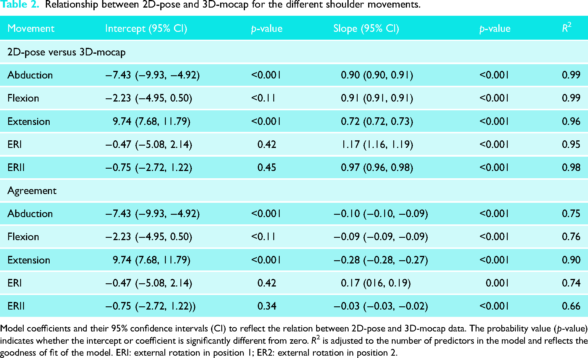
Model coefficients and their 95% confidence intervals (CI) to reflect the relation between 2D-pose and 3D-mocap data. The probability value (p-value) indicates whether the intercept or coefficient is significantly different from zero. R2 is adjusted to the number of predictors in the model and reflects the goodness of fit of the model. ERI: external rotation in position 1; ER2: external rotation in position 2.
The agreement between the two systems was assessed using Bland-Altman analysis. However, standard Bland-Altman analysis did not apply to the data as bias was mostly dependent on ROM. Therefore, bias and standard error of measurement were determined as follows. The difference was calculated by subtracting 2D-pose from 3D-mocap (i.e. negative values = overestimation, positive values = underestimation of 2D-pose). Error was then entered as the response variable, with 2D-pose-based shoulder angle as the predictor variable. Participants’ IDs were entered as an uncorrelated random effect for intercept. Data were modelled using linear equations, and bias was determined for any 2D-pose shoulder angle (Tables 2 and 4). The minimum detectable difference was determined as the average of the 95% CI level of the predicted error values from the observed 2D-pose shoulder movement range with Bonferroni corrected confidence intervals. This approach is like estimating the variance of the difference between the systems across participants. Therefore, if the difference between 2D-pose and 3D-mocap is consistent between participants (i.e. low variance across participants), the confidence interval of the predicted error using the linear mixed model would be low. Note that the minimal detectable difference is independent of the bias level between the systems and only reflects the consistency of the 2D-pose compared to the 3D-mocap estimated shoulder angle. Minimal detectable difference (MDD) has also been interpreted as the value above which a change can be attributed to a change above measurement error. 24
The exploratory analysis, using linear mixed-effect models, assessed the relationship of the difference between 2D-pose and 3D-mocap-based shoulder angle and 3D-mocap-based thorax orientation relative to the external reference frame. The bias was entered as the response variable, with 3D-thorax (either sagittal, frontal, or horizontal plane thorax angle) as predictor variable. Participants’ IDs were entered as an uncorrelated random effect. If the slope of the model is significantly different from zero, then thorax orientation compensation would significantly contribute to error. Point estimates and their 95% CI were determined using the maximum likelihood function with robust option. Adjusted R2 of models was determined.
Results
Comparison between 2D-pose and 3D-mocap ISB-based Euler decomposition
In terms of consistency, all 2D-pose-based shoulder movement angles showed a strong relationship with their 3D-mocap counterparts with an R2 value > 0.95 (see Table 2 for model coefficients, Figure 4). The MDD for all shoulder movement types ranged between 3.1° (extension) and 7.9° (ERI) (Table 3). In terms of agreement, all shoulder movements displayed a linear relationship between 2D-pose and 3D-mocap. The slopes were slightly below one, and the intercepts were below zero (Table 2). This indicates that the 2D-pose methods tended to overestimate the shoulder angle, with greater overestimation at larger than smaller ROM (Table 2), except for ERII and extension. ERII exhibited a slope greater than one, i.e. less overestimation at larger ROM than at smaller ROM, but this was not significant (Table 4). For extension, although linear, the slope (0.72 [0.72, 0.73]) was smaller than zero, and intercept (9.74 [7.68, 11.79]) was greater than zero. This indicates that the 2D-pose methods tended to underestimate extension at small ROM and overestimate extension at larger ROM (Tables 3 and 4).
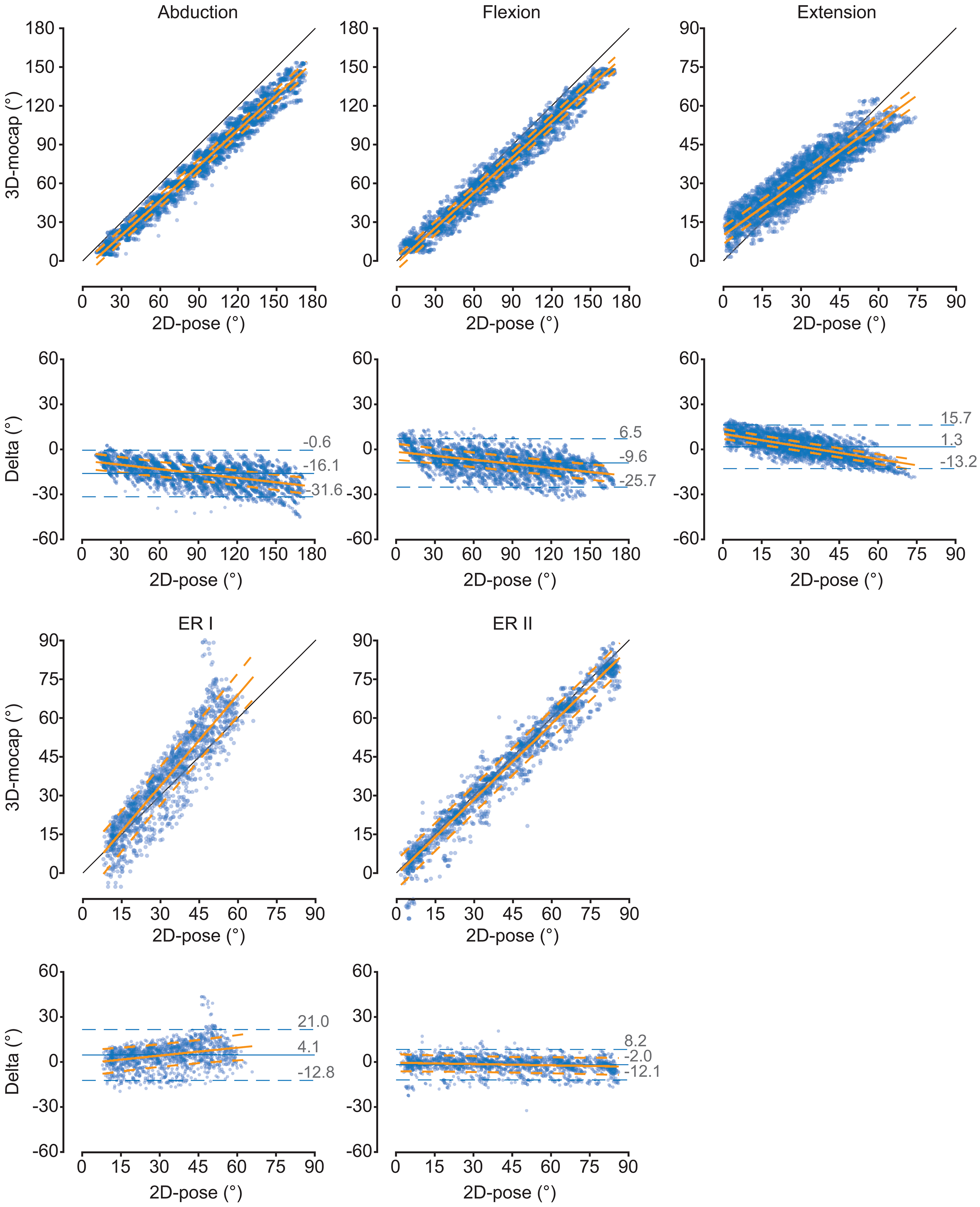
Comparison of the thoracohumeral shoulder angles between 2D-pose and 3D-mocap for the different shoulder movements. Scatter plots between 2D-pose (X-axis) and 3D-mocap (Y-axis) with an overlay of the linear mixed-model fit and 95% confidence intervals (CI) are displayed. The diagonal black line represents the line of identity. For each movement, the Bland-Altman plots show the 2D-pose estimated shoulder angle on the X-axis and the difference (Delta = 3D-mocap − 2D-pose shoulder range of motion) on the Y-axis. Bias (solid blue line) and 95% limits of agreement (LoA, dashed blue lines) are displayed. The orange solid line represents the linear fit, derived from the linear mixed model, between 2D-pose and the difference between the 2D-pose-based and 3D-mocap-based range of motion, with 95% CI (dashed orange lines). ERI: external rotation in position 1; ER2: external rotation in position 2.
Minimum detectable difference for the different shoulder movements.
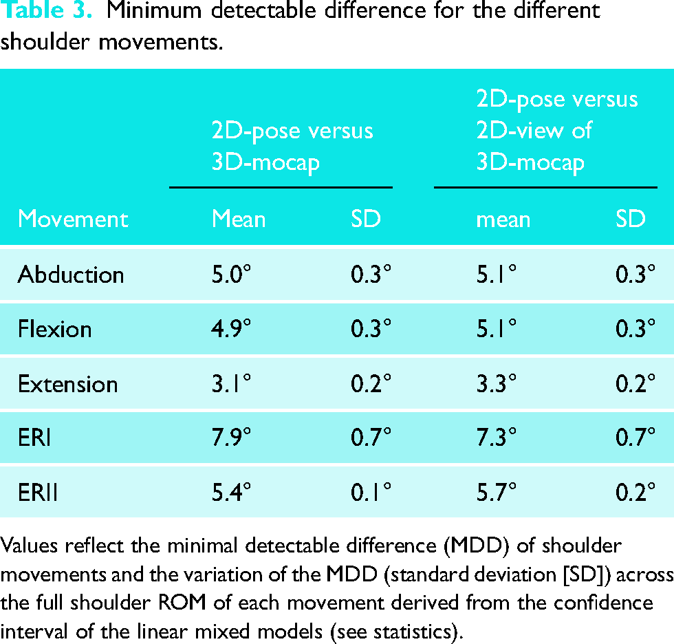
Values reflect the minimal detectable difference (MDD) of shoulder movements and the variation of the MDD (standard deviation [SD]) across the full shoulder ROM of each movement derived from the confidence interval of the linear mixed models (see statistics).
Difference between 2D-pose and 3D-mocap at selected shoulder angles for the different movements.
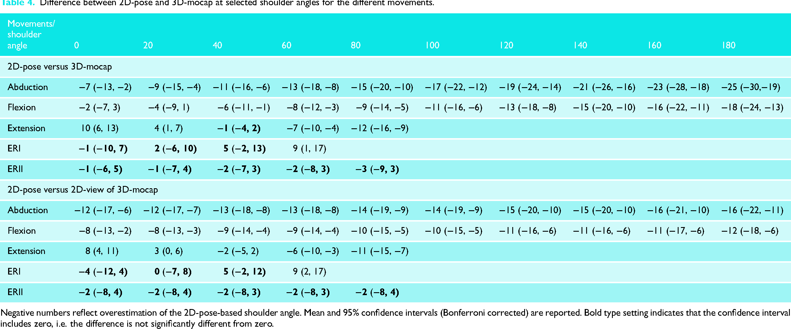
Negative numbers reflect overestimation of the 2D-pose-based shoulder angle. Mean and 95% confidence intervals (Bonferroni corrected) are reported. Bold type setting indicates that the confidence interval includes zero, i.e. the difference is not significantly different from zero.
For functional internal rotation, the distributions of the normalised spine locations when there was a change in quadrant suggest consistency in the 2D-pose-based measures (Figure 2). There is a clear separation of the upper and lower bounds of quadrants 2 and 3 (p < 0.001, Figure 2).
Comparison between 2D-pose and 2D-view of 3D-mocap
The outcomes in terms of consistency comparing the 2D-pose and 2D-view of 3D-mocap are similar to when 2D-pose was compared to 3D-mocap ISB-based Euler decomposition (Tables 4 and 5, Figure 5). However, there are some differences in terms of agreement when compared to 2D-pose and 3D-mocap ISB-based Euler decomposition (Table 4). Except for extension, all intercepts were lower than the intercepts of the relationship between 2D-pose and 3D-mocap ISB-based Euler decomposition. Except for ERII, however, the slopes were closer to one. This indicates that overestimation is larger at lower shoulder ROM than 2D-pose compared to 3D-mocap, but overestimation remains consistent throughout the ROM (Table 4, Figure 5). For ERII, the slope was greater than one (Table 5), but differences between the 2D-pose and 2D-view of 3D-mocap were also not significantly different (Table 4).
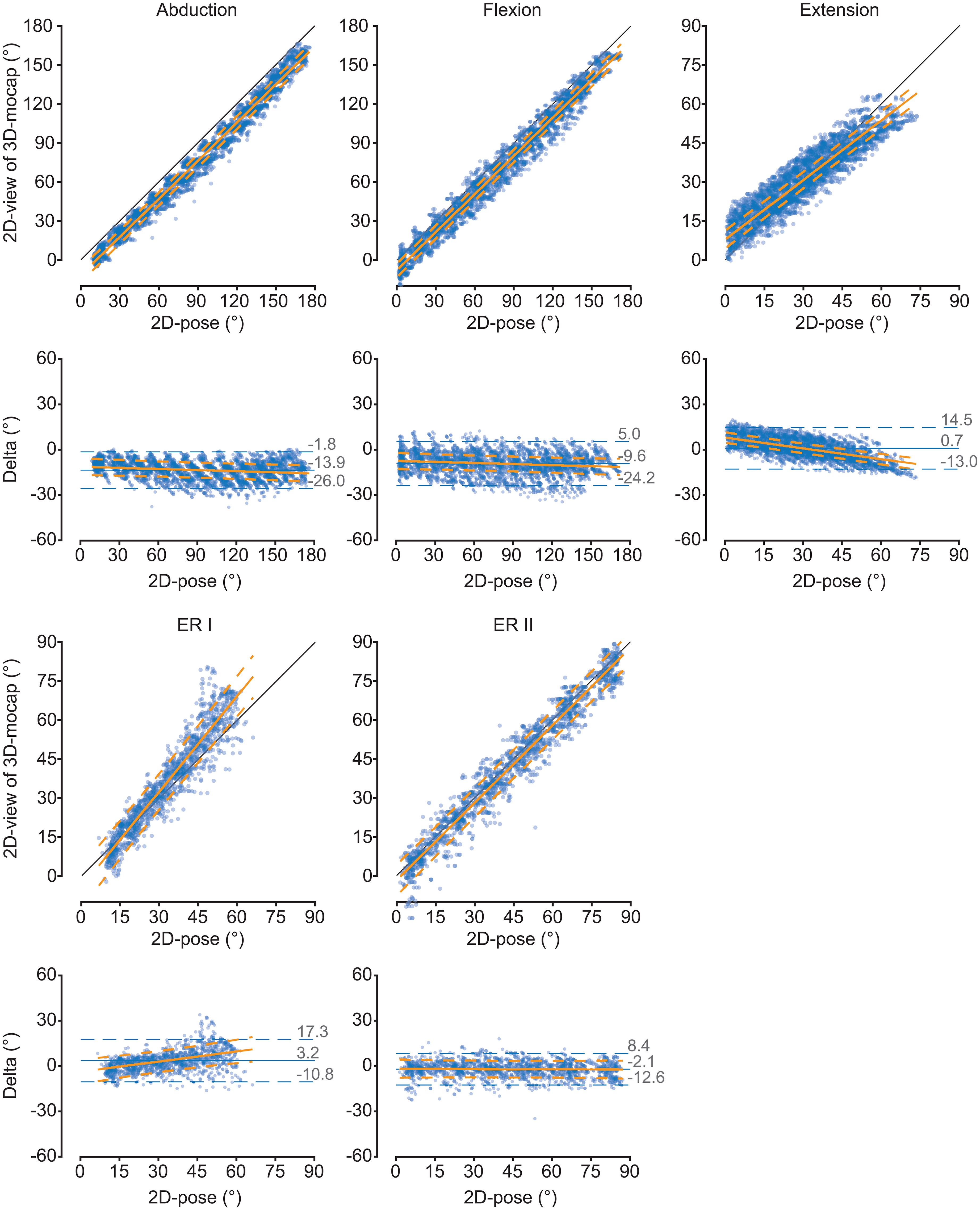
Comparison of the thoracohumeral shoulder angles between 2D-pose and 2D-view of 3D-mocap (from phone camera's perspective) for the different shoulder movements. Scatter plots between 2D-pose (X-axis) and 3D-mocap (Y-axis) with an overlay of the linear mixed-model fit and 95% confidence intervals (CI) are displayed. The diagonal black line represents the line of identity. For each movement, the Bland-Altman plots show the 2D-pose estimated shoulder angle on the X-axis and the difference (Delta = 3D-mocap − 2D-pose shoulder range of motion) on the Y-axis. Bias (solid blue line) and 95% limits of agreement (LoA, dashed blue lines) are displayed. The orange solid line represents the linear fit, derived from the linear mixed model, between 2D-pose and the difference between the 2D-pose-based and 2D-view of 3D-mocap-based range of motion, with 95% CI (dashed orange lines). ERI: external rotation in position 1; ER2: external rotation in position 2.
Relationship between 2D-pose versus 2D-view of 3D-mocap for the different shoulder movements.
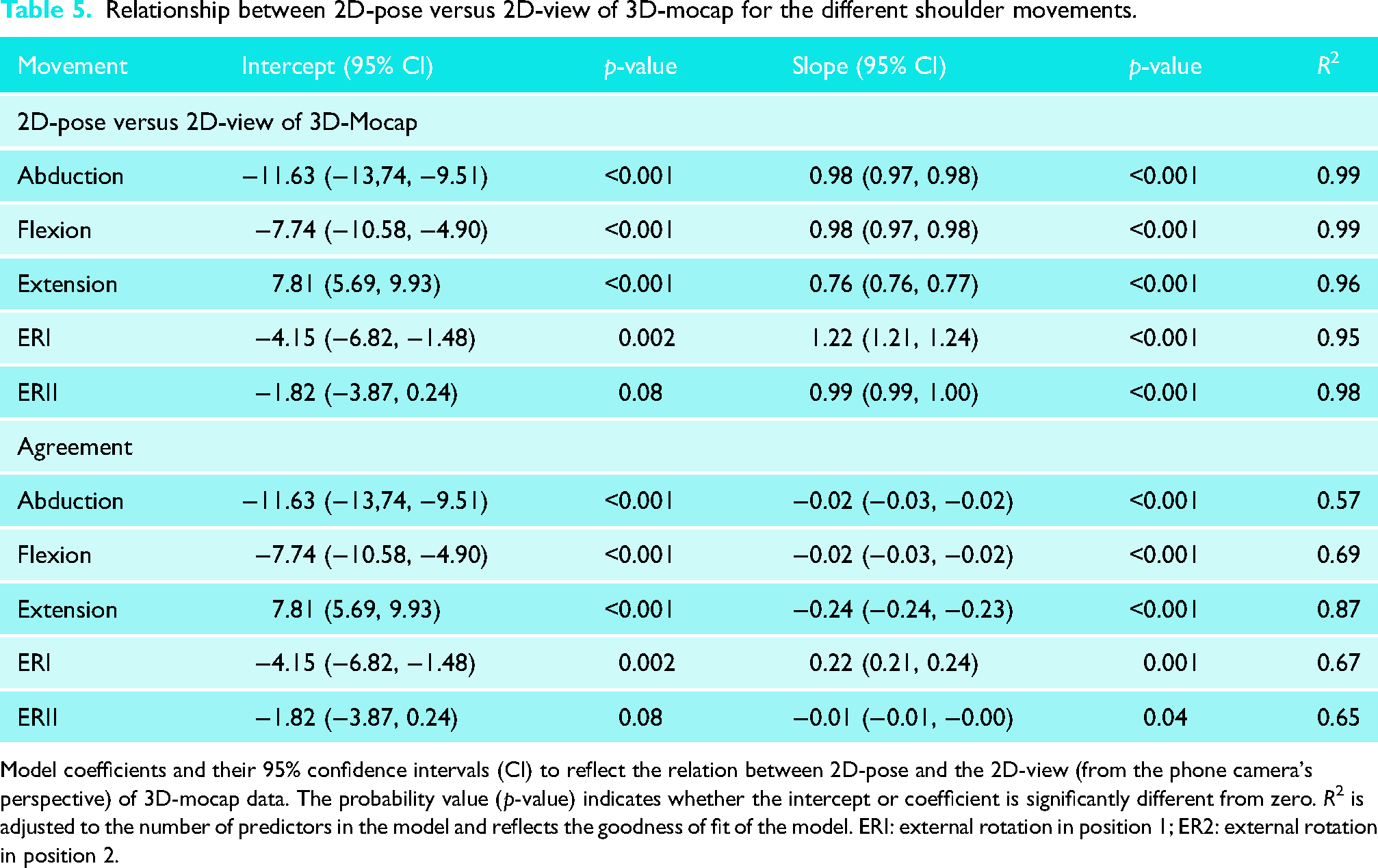
Model coefficients and their 95% confidence intervals (CI) to reflect the relation between 2D-pose and the 2D-view (from the phone camera's perspective) of 3D-mocap data. The probability value (p-value) indicates whether the intercept or coefficient is significantly different from zero. R2 is adjusted to the number of predictors in the model and reflects the goodness of fit of the model. ERI: external rotation in position 1; ER2: external rotation in position 2.
Outliers in the Bland-Altman plots (Figures 4 and 5) could be explained by fluctuations in the detected 2D pose-based key body landmarks.
Thoracic contribution to the difference between 2D-pose and 3D-mocap ISB-based Euler decomposition
The contribution of the thorax relative to the volume, in the same plane as the arm movement, was associated with the difference between 3D-mocap and 2D-pose-based shoulder angles (R2 > 0.56, see Table 6 for model coefficients). When the thorax was laterally flexed away from the moving arm, it led to an overestimation of abduction: 1.39° [1.29, 0.49]) was associated with 1° difference between 2D-pose and 3D-mocap. Similarly, thoracic extension caused overestimation of both shoulder flexion and extension. Shoulder flexion, 1.27° [1.08, 1.46], and shoulder extension, 2.06° [1.99, 2.13], of thorax compensation in the sagittal plane were associated with 1° difference between 2D-pose and 3D-mocap, respectively.
Relationship of the difference between 2D-pose and 3D-mocap with thoracic orientation relative to the external volume.
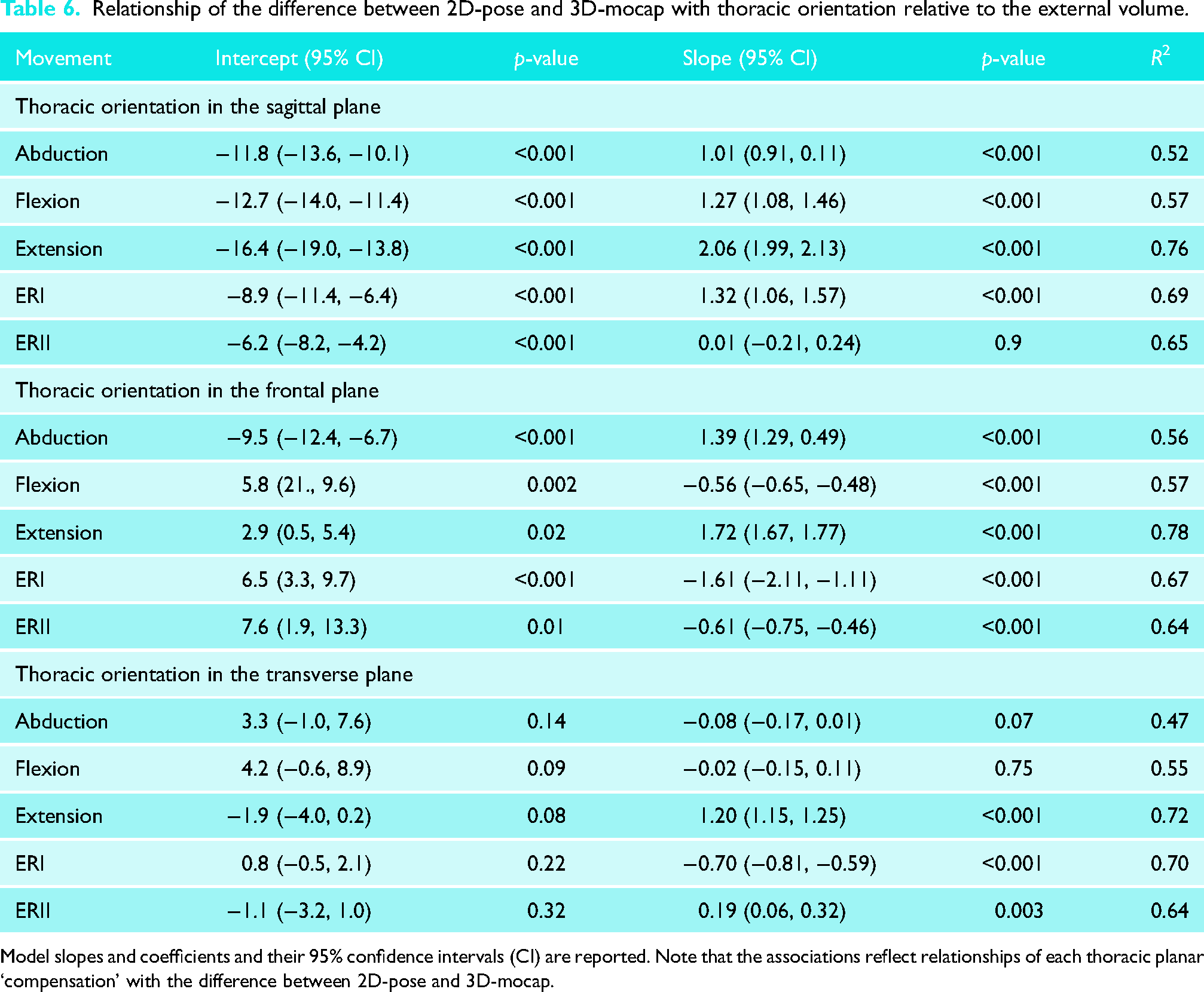
Model slopes and coefficients and their 95% confidence intervals (CI) are reported. Note that the associations reflect relationships of each thoracic planar ‘compensation’ with the difference between 2D-pose and 3D-mocap.
Orientation of the thorax in different planes also impacted this difference. Thoracic extension while performing abduction resulted in overestimation of abduction angle (R2 = 0.52); 1.01° [0.91, 0.11] of thoracic extension was associated with 1° difference between 2D-pose and 3D-mocap. More lateral flexion of the thorax towards the moving arm led to an overestimation of flexion (R2 = 0.57); −0.56° [−0.65, −0.48] of thoracic lateral flexion was associated with 1° difference between 2D-pose and 3D-mocap. Increased lateral flexion away from the moving arm (R2 = 0.78) and thoracic rotation (R2 = 0.72) towards the moving arm contributed to an overestimation of extension; for shoulder extension, thoracic lateral flexion of 1.72° [1.67, 1.77] and thoracic rotation of 1.20° [1.15, 1.25] were associated with 1° difference between 2D-pose and 3D-mocap, respectively.
Furthermore, greater thoracic flexion caused an underestimation of ERI (R2 = 0.69); 1.32° [1.06, 1.57] of thoracic flexion was associated with 1° difference between 2D-pose and 3D-mocap. In contrast, increased thoracic lateral flexion (R2 = 0.64) and thoracic rotation (R2 = 0.64) towards the moving arm led to an overestimation of ERII; −0.61° [−0.75, −0.46] of thoracic lateral flexion, and 0.19° [0.06, 0.32] of thoracic rotation was associated with 1° of difference between 2D-pose and 3D-mocap. Notably, more lateral flexion (R2 = 0.67) and rotation of the thorax (R2 = 0.70) towards the moving arm reduced the discrepancy between 3D-mocap and 2D-pose-based shoulder angles for ERI.
Discussion
The shoulder angle time series estimated with 2D-pose closely matched the shoulder angles derived from 3D mocap based on the ISB recommendations and 2D-view of 3D-mocap in individuals without shoulder issues. This was particularly true for shoulder abduction, flexion, and ERII. Differences in shoulder ROM between 2D-pose and 3D-mocap likely stem from variations in defining local anatomical reference frames between the systems. In addition, the definition of the ‘thorax’ using 2D-pose data affects how thoracic contributions to shoulder movements are considered. These differences may account for some of the discrepancies (agreements) observed between the systems. The findings suggest that when quantifying shoulder ROM from segmental motions of the upper body and upper arm using 2D-pose data from a smartphone device, it is crucial to consider these factors (anatomical frame definition, thorax contribution). This understanding is important for the accurate use and interpretation of shoulder ROM data obtained from 2D-pose technologies.
The thorax anatomical frame definition in 2D-pose-based was adapted from a previous validation study, 8 to lower the bias in thoracohumeral angle estimation compared to 3D-mocap motion capture. By averaging the positions from bilateral shoulder and hip joint positional estimations, the abduction angle bias was reduced by approximately 10°–15° throughout the movement range. The accuracy of shoulder flexion and extension was comparable with van den Hoorn et al. 8 This study builds on previous findings 8 by comparing external rotation at positions I and II and functional internal rotation (discussed below).
The difference between 2D-pose and 3D-mocap-based shoulder ROM stems from the variation in thorax anatomical reference frame definition. Due to limited landmarks in the thorax region in 2D-pose, the thorax anatomical frame is not well defined. As a result, the 2D-pose-based thoracohumeral shoulder angle may not accurately represent the true orientation of the thorax relative to the global frame. When the 2D-pose-based thorax is determined using estimated shoulder and hip locations, errors in shoulder angle can occur, especially when the upper thorax moves relative to the lower spine. Our exploratory analysis revealed that some of the errors were indeed related to thoracic compensations, even when participants were instructed to minimise thoracic orientation changes during the shoulder movements. It is important to note that the association between thoracic orientation and the difference between 2D-pose and 3D-mocap was analysed separately for each plane. Differences between systems cannot be combined across the different planes of thoracic compensation. During certain shoulder movements, thoracic contributions or compensations are likely coupled. 25 Similarly, the ISB-based thorax in 3D-mocap is assumed to be a rigid segment which is not entirely accurate. This assumption might introduce errors in the 3D-mocap-based thoracohumeral angle. Taken together, it is critical to recognise that thoracic compensations influence the observed thoracohumeral angle regardless of the system used. However, the impact is likely greater in 2D-pose-based thoracohumeral angle estimation compared to 3D-mocap. This becomes critical when quantifying active shoulder range in individuals with limited glenohumeral ROM (e.g. post-surgical interventions), who may compensate by altering thorax orientation to increase arm range. Therefore, clear instructions and verification of adherence to these instructions are essential for accurate shoulder ROM measurement.
Compared to the other shoulder movements, 2D-pose-based thoracohumeral extension and ERI exhibited the worst comparison between 2D-pose and 3D-mocap. The 2D-pose-based extension error was linked to multiplanar thoracic compensation and likely contributed to the overestimation of extension at larger ROM (>45°). Conversely, extension was underestimated at a smaller extension angle (<15°). This discrepancy may be due to inaccurate tracking of the hip position. When the arm is extended, it can temporarily block the view of the hip, affecting tracking of 2D-pose-based joint locations displayed in real-time on the video. These tracking fluctuations can alter thorax orientation and consequently influence the calculation of thoracohumeral extension angle. Applying a median filter to the raw joint positions from 2D-pose or using simple linear interpolation over obscured time points might reduce these artefacts. However, we cannot confirm this since we did not have access to the raw time-series of landmark locations.
Quantifying ERI from the frontal view of the participant is challenging. Despite this difficulty, the 2D-pose-based ERI angles closely matched those estimated from 3D-mocap. At very small ERI angles, the phone camera's projection of the wrist and elbow positions in 2D-pose overlapped and tended to fluctuate due to the positional estimate uncertainty. Detecting small changes accurately relies on both reliable 2D-pose position estimates and video resolution (12MP in our case), which poses challenges in capturing small (<1 cm) distance changes. To address this, the mymobility® app automatically lowered confidence in estimates for smaller (<20°) and larger (>45°) ERI angles, and detectable limit ROM is limited to these values. However, data up to 60° were exported noting that errors linearly increase with larger ROM (Table 4). Given the fluctuations in 2D-pose-based elbow and wrist positions, we applied a median filter to the angular data. Again, it might be more effective to apply the median filter to the raw landmark positions of the elbow and wrist before calculating the angle.
Few studies have investigated the accuracy of single-camera 2D-pose-based shoulder range of motion.26–31 Comparisons are complicated by the use of different gold standards and diverse deep learning models to estimate body landmark positions in 2D-pose. In a study comparing against a 3D-mocap-based in-house kinematical model, Clemente et al. 26 evaluated shoulder flexion/extension and abduction using MediaPipe Pose. The consistency between 2D-pose and 3D-mocap in our current study aligns well with Clemente's findings. 26 However, their abduction consistency was lower than ours, likely due to marker occlusion at the hip during sitting shoulder flexion. Our results on the consistency of abduction, flexion, and extension also align with our previous preliminary study. 8 The current study used the same methodology, but we extended our findings using time-series data instead of limited shoulder holds at different ranges. The variance accounted for in our study is slightly higher than in our previous work, 8 likely because we included the full active ROM, i.e. by including more data points.
Some studies have compared automated pose estimation using various versions of Microsoft Kinect cameras/software10,11,32 against 3D-mocap. However, none of these investigations used ISB-based local anatomical reference frames for comparison. Instead, they either used reflective markers positions that mimicked the positions of the landmarks identified by pose estimation11,32 or used the Plug-in Gait model. 10 Faity et al. 11 selected similar marker positions between systems but found surprisingly low correlation values between 3D-mocap and pose-based estimation of shoulder abduction (R2 = 0.13) and flexion (R2 = 0.37). These R2 values are considerably lower than our findings for shoulder flexion/abduction and those reported by Zulkarnain et al. 32 The low consistency could potentially be attributed to the oblique positioning of the Kinect camera relative to the floor. Although this was corrected by rotating positional data prior to analysis, it might have affected the accuracy of initial pose detection. Zulkarnain et al. 32 observed lower bias for flexion and abduction compared to our results. This difference could be due to the creation of similar anatomical reference frames between systems (3D-mocap and Kinect pose) to determine the thoracohumeral angle. In addition, Wilson et al. 10 compared their results against the Plug-in Gait kinematic upper limb model and observed minimal bias in abduction and flexion.
Several limitations require consideration. First, our participants had no shoulder issues, so the external validity of the results may be limited to this specific demographic. Future studies should include older individuals and those with shoulder problems to broaden the applicability of the findings. Second, our 2D-pose-based joint position estimates were derived from the Skeletal Tracking Shoulder Range of Motion Assessments feature (using the Apple Vision framework), and other machine learning-based 2D-pose methods may produce different results. The accuracy of the 2D-pose-derived body landmark estimates likely depends on the training data set and annotation method used. Unfortunately, this information is proprietary and not disclosed by Apple Inc. Third, we considered ISB-based motion capture as the ‘gold standard’ for estimating bone by tracking reflective markers on the skin. However, these marker positions can be affected by skin movement artefacts.33–35 Both systems aim to estimate underlying bone motion based on external reference points and are thus inherently subject to some degree of error. To better quantify systematic errors in 2D-pose estimation, alternative approaches are required that eliminate soft-tissue artefacts, such as cadaveric, 36 in-vivo bone-pin, 37 or biplane fluoroscopy-based studies. 38 These methods provide direct access to bony orientation and could serve as a gold standard to determine the accuracy of 2D pose-based joint angle estimations. Future studies incorporating such techniques may offer more definitive proof-of-concept validation for 2D pose accuracy. Fourth, while we ensured that participants performed shoulder movements in line with the phone camera's plane, any out-of-plane movements could have contributed to the difference between the 2D-pose and 3D mocap-based angle. This limitation has important implications for any application relying on 2D pose estimation. Smartphone-based single-camera methods offer strengths such as ease of setup, local processing, and the ability to objectively quantify ROM. However, there are key weaknesses; accurate assessment depends on strict adherence to standardised positioning and camera alignment 8 and avoidance of thoracic compensation. User instructions should emphasise that shoulder movements must occur within the camera's plane while minimising thoracic compensation. Deviation from these parameters can lead to erroneous ROM estimates, potentially impacting clinical interpretation. These constraints may limit clinical applicability and the ability to track changes in shoulder ROM at different time points if not properly controlled. Moreover, if used without professional oversight, there is a risk of misinterpretation, particularly if users assume that self-measured ROM data are sufficient for clinical decision making. It is important to recognise that shoulder ROM should be considered alongside multiple clinical indicators and not in isolation. Future research should focus on improving thoracic reference frame definition to better account for thoracic contributions and developing automated machine learned validation checks that provide a confidence score indicating whether movements remain within the camera's plane. Because 2D pose estimation methods cannot be used to quantify more complex, out-of-plane shoulder movements, other multi-camera (3D pose) or inertial measurement unit approaches are required (see van den Hoorn et al. 39 for an overview of different methods). Two or more calibrated cameras allow 3D reconstruction of key body landmarks (e.g. OpenCap workflow 40 ), after which a machine learned algorithm can infer a full virtual marker set and drive a musculoskeletal model via inverse kinematics. 40 Inertial measurement units can also be fused with optical key-points to improve segment orientation tracking, although sensor placement, magnetometer calibration, and added setup time currently limit their practicality for routine clinical or at-home assessments. Multi-camera systems are therefore most feasible in clinical settings, whereas single-camera solutions remain attractive for remote monitoring. Because most upper limb pose models use a similar thoracic reference frame, further work on more anatomically faithful thorax definitions is essential for accurately identifying and correcting thoracic compensations. Last, comparing functional internal rotation between 2D-pose and 3D mocap is challenging due to the different methods each system uses to quantify IR ROM. While the consistency of IR zone identification was high, limiting IR ROM to specific zones reduces the resolution needed to detect changes over time or differences between groups.
2D-pose-based shoulder ROM offers a promising and practical tool for objectively quantifying active shoulder motion, showing favourable comparison against 3D mocap. However, when using a single smartphone-based 2D-pose to measure shoulder ROM, it is crucial to consider its limitations in both measurement and interpretation. For instance, it is important to account for the thoracic contribution to shoulder ROM to ensure that changes in shoulder ROM reflect actual improvements or deterioration. This ensures that medical guidance and decisions are based on valid and reliable data. While we observed high consistency between the methods, the differences in agreement mean that the methods should not be used interchangeably.
Footnotes
Acknowledgements
We thank the participants for providing their time for this study.
Author contributions
W.v.d.H., M.L., F.H., R.P.V., F.B.-M., K.C., A.G. and G.K. Conceptualisation: W.v.d.H., M.L., F.H., R.P.V., F.B.-M., K.C., A.G. and G.K. Data curation: W.v.d.H. Formal Analysis: W.v.d.H. Funding acquisition: K.C., A.G. and G.K. Investigation: W.v.d.H., M.L., F.H., R.P.V., and F.B.-M. Methodology: W.v.d.H., M.L., F.H., R.P.V., F.B.-M., K.C., A.G., and G.K. Project administration: W.v.d.H. and G.K. Resources: G.K. Software: W.v.d.H. Supervision: W.v.d.H. and G.K. Visualisation: W.v.d.H. Writing – original draft: W.v.d.H. Writing – review and editing: W.v.d.H., M.L., F.H., R.P.V., F.B.-M., K.C., A.G., and G.K.
Consent to participate
All participants provided written informed consent prior to participating.
Consent for publication
Informed consent for publication was provided by the participant(s) for use of their images.
Data availability
The source data are available upon reasonable request.
Declaration of conflicting interests
The authors declared no potential conflicts of interest with respect to the research, authorship, and/or publication of this article.
Ethical approval
This study was approved by the Queensland University of Technology Research Ethics Committee (approval no. 2000000470) on 25 August 2020.
Funding
The authors disclosed receipt of the following financial support for the research, authorship, and/or publication of this article: This research was funded by the Australian Research Council (ARC) Industrial Transformation and Training Centre for Joint Biomechanics (IC190100020) of which Zimmer Biomet is an Industry partner.