
Abstract
A numerical study is described to predict, in the non-boiling regime, the heat transfer from a circular flat surface cooled by a full-cone spray of water at atmospheric pressure. Simulations based on coupled computational fluid dynamics and conjugate heat transfer are used to predict the detailed features of the fluid flow and heat transfer for three different spray conditions involving three mass fluxes between 3.5 and 9.43 kg/m2s corresponding to spray Reynolds numbers between 82 and 220, based on a 20 mm diameter target surface. A two-phase Lagrange–Eulerian modelling approach is adopted to resolve the spray-film flow dynamics. Simultaneous evaporation and condensation within the fluid film is modelled by solving the mass conservation equation at the film–continuum interface. Predicted heat transfer coefficients on the cooled surface are compared with published experimental data showing good agreement. The spray mass flux is confirmed to be the dominant factor for heat transfer in spray cooling, where single-phase convection within the thin fluid film on the flat surface is identified as the primary heat transfer mechanism. This enhancement of heat transfer, via single-phase convection, is identified to be the result of the discrete random nature of the droplets disrupting the surface of thin film.
Keywords
Introduction
Spray cooling has been the subject of research focused on several important potential application areas.1–7 These applications mainly include cooling in grid power generation systems and power electronics, where in some cases traditional convective cooling methods have reached their physical limitations. The ultimate aim of the current study is an automotive application focusing on robust spray cooling for thermal management of highly boosted combustion engines used in hybrid electric vehicles. In recent years, a wealth of experimental evidence has been obtained to highlight the benefits of using spray cooling. However, as a method of thermal management, spray cooling has not yet been industrially applied to any significant degree. The most likely cause for this is a lack of theoretical understanding of the underlying heat transfer mechanisms. These mechanisms inherently occur at small scale involving complex interactions of several phenomena such as droplet break-up, impingement, thin fluid film formation, convection, conduction, nucleation, and phase change. The performance of spray cooling is known to depend on many factors including nozzle type, spray volumetric flux, droplet size, spray angle, orifice-to-surface distance, and the degree of fluid ‘sub-cooling’.8–14
Despite numerous studies, knowledge of the fundamental heat transfer processes in spray cooling is still limited owing to the complexity of the mechanisms described. Heat transfer models are limited to prediction under specific conditions corresponding to particular experimental test conditions. 15 Experimentally derived correlations involve a large number of test conditions to achieve an optimum combination of dependent parameters for any particular cooling condition. Computational fluid dynamics (CFD) modelling by contrast can significantly improve the current state-of-the-art prediction capability by including important physical effects. These include droplet momentum and wall impingement, fluid film thickness, gravity, surface tension, and phase change, leading to better understanding and more reliable spray cooling simulation and subsequent system design. Spray cooling, however, occurs over a diverse range of length scales involving thousands of droplets that are orders of magnitude smaller in diameter than the target surface length scale. This requires very significant computational power making direct simulation of all aspects of spray cooling quite unfeasible. Alternatively, a Lagrange–Eulerian approach 16 allows the multiple scales associated with spray cooling to be numerically resolved resulting in acceptable simulation times. In this framework, spray formation and droplet dynamics are traced individually (in representative ‘parcels’) until they impinge on a fluid layer or wall, where mass, momentum, and energy transfer takes place between a droplet and the wall or film.17,18 A wall-impingement model then accounts for the mass that rebounds, splashes, or adheres to the film, resulting in redistribution of momentum and thermal energy for both the liquid film and any rebounding droplets.
Rahman et al. 17 numerically modelled and simulated a swirling jet flow from a nozzle using the volume-of-fluid method to study spray formation characteristics for several fluids, including water. It was observed that the pressure drop in the spray nozzle increases with flow rate and that the properties of the liquid have a significant effect on the spray cone angle. Stanton and Rutland 19 developed a two-dimensional wall film model to solve the mass continuity and momentum conservation equations. This includes the effects of spray droplet impingement and splashing using a set of correlations to express the distribution of mass and momentum for the incident droplet as a function of key dimensionless groups. CFD simulations by Sarkar and Selvam 20 showed a significant increase in the ratio of the local transient heat flux to the average heat flux of the thin film within droplet impact cavities. Bai et al. 21 developed a spray impingement model for gasoline spray wall impact simulations. The model was assessed by simulating experimental conditions for oblique spray impingement in a wind tunnel, resulting in good agreement between the calculated wall spray characteristics and experimental measurements. Jafari 22 simulated single-phase combined spray and film heat transfer using the Bai–Gosman impingement model. 21 This model applies to a surface temperature below boiling for the fluid spray, where the error in the predicted heat transfer coefficient was 9%. Youssef 23 used numerical simulations to study rewetting of a hot surface by droplet impingement and found that cooling is improved by increasing spray velocity (owing to increased momentum in the liquid layer impacted by the spray). Simulations also showed that cooling is improved by a reduction in the distance between the nozzle and the hot surface, and by an increase in the spray mass flow rate. Meredith et al. 24 developed a model for simulating water film transport over a solid surface and coupled it with a gas-phase solver and spray transport model. This predicted good agreement with experimental measurement for film thickness, velocity, and mass flow rate.
A review of evaporative cooling concepts used in automotive applications suggests a combination of single-phase and fully evaporative cooling may offer the most practical approach to implementation. 25 Pautsch and Shedd, 14 from an extensive parametric study of spray cooling using different nozzle patterns, showed that the heat transfer associated with phase change may contribute up to 30% of the total cooling. It was found that systems with the highest peak heat fluxes were obtained when phase change was avoided. It was also suggested that cooling is dominated by single-phase heat transfer in spray systems with liquid film formation on the heated surface. Accurate assessment of spray cooling in the single-phase non-boiling regime is therefore deemed essential for robust spray cooling system design. In the non-boiling regime, the wall temperatures are below the coolant boiling point. Impinging spray droplets on the heated wall form a liquid film on the surface which is swept away by the stream of coolant droplets removing heat by substantial forced convection, plus some heat removal by evaporation of the liquid film, which is just below saturation temperature. Some experimental studies have examined spray impingement heat transfer in the non-boiling regime.6,26–28 Kalantari 27 studied the influence of film thickness on droplets–wall interaction and developed a theoretical model to predict the average film thickness as a function of mean Reynolds number, mass flux density of the impacting droplets, and the average droplet diameter. Experiments by Ciofalo, 26 using water sprays with mass fluxes between 8 and 80 kg/m2s, indicated that the single-phase heat transfer coefficient depended strongly on the product of mass flux and mean droplet velocity, with no significant dependence on droplet diameter. Karwa et al. 28 studied the heat transfer in the non-boiling regime using a pressure atomization nozzle, developing a correlation between Nusselt number and the spray Reynolds number.
Liquid–vapour phase change can occur at two different states: (i) when the temperature is higher than the saturation temperature (based on the local water vapour concentration) and where evaporation is governed by the partial pressure of the vapour (i.e. until 100% relative humidity is reached), and (ii) when the boiling temperature is reached (which is fixed by the air–vapour mixture pressure). None of the CFD studies in the non-boiling regime have considered the effect of film evaporation, which has generally been assumed to make only a small contribution to the total heat transfer. Therefore, for accurate heat transfer prediction numerical simulation should include the full effects of both droplet and liquid film dynamics for both convective and evaporative heat transfer at impinged solid walls. It is also often a requirement to know how the heat transfer occurs within the cooled hot metal and the adjacent coolant fluid. To date, there have been no studies of spray cooling using complete CFD–conjugate heat transfer (CHT) simulations which include evaporation effects in the non-boiling regime. The main objective of the current study is to develop and verify CFD–CHT simulations for non-boiling spray cooling on a flat circular surface as a precursor to application of spray evaporative cooling simulations to the curved geometries under engine-like operating conditions. The geometry and thermal configurations are based on the experimental work of Karwa et al. 28 Simulations are achieved using a finite-volume CFD solver STAR-CCM + (V11.04) in a Lagrange–Eulerian framework. First, the modelling and simulation approach is described. Then, CFD simulation results are reported, showing a comparison with published experimental measurements.
Numerical modelling
A description of the modelling features is now given to explain how the particular commercial CFD code used is configured to simulate the particular spray scenario described. This is followed by a formal statement of the equations governing spray evolution with the phase change, the boundary conditions, and the meshing details.
Simulations are based on coupling the Lagrangian description of the liquid phase (i.e. a water spray) with an Eulerian description of the gas phase. The spray comprises ‘parcels of droplets’ of differing sizes undergoing simultaneous effects as they travel within the mixture of air and water vapour. The segregated solver is used employing a ‘simple’ algorithm 29 to couple pressure and velocity. The Lagrangian phase is solved by tracking droplets through the calculated flow field. The spray droplets exchange momentum, mass, and energy, with the Eulerian flow field – their trajectories being computed individually at specified intervals during the fluid phase calculation. The possible aerodynamic force-induced break-up of droplets in the early stages of the spray leaving the nozzle are accounted for by the TAB break-up model. Liquid-film build-up resulting from impingement of droplets on the solid surface is resolved in the Eulerian framework. This makes it possible to predict liquid film transportation, heat transfer, and possible disintegration of the film into secondary drops. Interaction of spray droplets with the liquid-filled control volumes, i.e. a ‘stick or splash’ scenario, is dependent on parameters such as the droplet Weber number and velocity. This dependence is predicted by Bai–Gosman model. 21 At low Weber numbers, i.e. < 2, droplets stick to the wall contributing to liquid film. At higher Weber numbers, droplets splash, ejecting secondary droplets.
The Standard 3D Reynolds-Averaged Navier–Stokes equations, as well as transport equations for mass, energy, and species (air/water vapour) conservation, are solved for the Eulerian phase as the continuum flow field. The governing equations for conservations of mass, momentum, and energy are


The terms

Turbulent interaction between the water spray and the continuum field is simulated using the realizable k–ɛ turbulence model. 30 The turbulent Prandtl and Schmidt numbers for the continuous phase in the present study are set to 0.9, i.e. the recommended values in STAR_CCM+. For the fluid film layer, conservation equations of mass, momentum, and energy are solved and integrated over the volume of fluid film in each cell to obtain a set of algebraic equations. Both the quantity of mass impinging on the film, and the source terms for splashing, are computed by the impingement model. 21 Evaporation of the fluid film into the gas phase and condensation from a gas phase into the fluid film are modelled by solving the mass conservation equation at the film–continuum interface. 29 Evaporation and condensation are allowed for by component mapping and by use of the Antoine equation for saturation pressure of water.
Droplets moving in the gaseous field encounter inertia and hydrodynamic drag forces and can therefore be accelerated or decelerated. The droplet velocity change is thus given by


Evaluation of spray parameters
Spray parameters according to experimental conditions used in Karwa et al. 28
The experimental heat transfer coefficient h is defined as


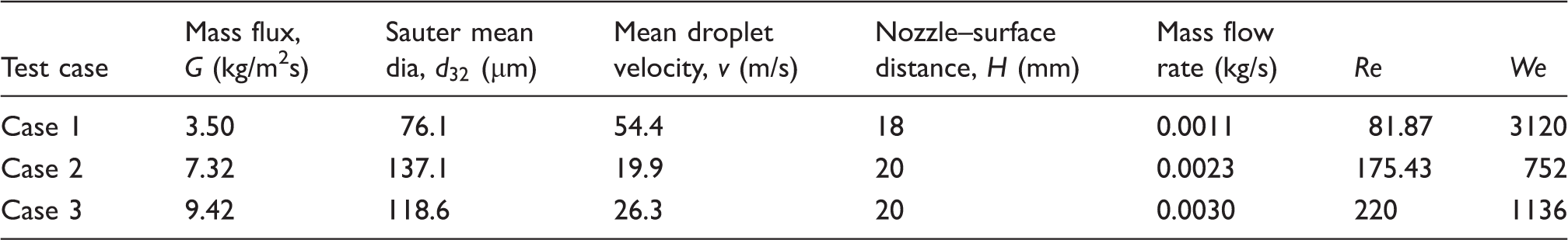
Boundary conditions
Given the experimental spray parameters (mass flow rate, droplet size, and velocity), a point spray nozzle is introduced to the domain through a number of computational ‘parcels’ representing the total population of dispersed phase. The velocity and diameters are given for droplets at the nozzle exit point. Each parcel stream then has part of the total droplets generated. In effect, parcels can be considered as a discretization of the population of dispersed phase in the same way that cells are a discretization of continuous space. As with cells, the number of parcels must be large enough so that the properties of the full population of spray droplets are represented. Calculations involved 1000, 2000, and 3000 parcels to ensure the spray droplet density is adequately represented. An initial air-vapour field is assumed to be air with 5% humidity. The spray flow is assumed to be water at an ambient temperature of 25℃. The nozzle axis is always kept normal to the surface. A uniform droplet size at the nozzle discharge was used. The droplet diameter at the nozzle exit can be specified with a constant, a log-normal distribution, or some other distribution. A constant value was used corresponding to the experimental conditions (which itself is estimated using a correlation). Uniform velocity distribution is assigned to the spray nozzle inlet to match the experimental conditions. The spray cone angle was calculated to correspond to the experimental conditions such that spray impact area is just equal to the heater surface. The inlet conditions for turbulence were assumed to have 1% turbulent intensity and a 1 mm length scale. The outlet boundaries of the main computational domain correspond to constant atmospheric pressure according to the experiment. The walls in the computational domain have non-slip boundary condition and all except the cooled surface are adiabatic. The initial condition for fluid film was zero thickness. A fixed uniform heat flux was applied at the bottom of the hot surface for all three cases. The experimental heating power was chosen, so that the hot surface temperature was maintained below 95℃ (i.e. a heat flux between 30 and 85 W/cm2 for the entire range of mass fluxes). The spray chamber pressure was maintained at atmospheric throughout the study.
Geometry and mesh
Figures 1 and 2 show the computational domain, grid, and boundary conditions used for the simulation of the experimental data published in Karwa et al.
28
The computational domain is discretized using polyhedral cells which include prism grid layers in the film region with mapped interfaces between the solid domain, fluid film, and air-vapour continuum field. A grid convergence test was undertaken for Case 1 (Table 1), respectively, with 98,000 and 430,000 cells, showing no significant difference in predicted surface temperature when the grid density was increased. The simulation results were therefore obtained using a mesh of 98,000 cells.
Flow domain and boundary conditions. Views of computational grid on domain boundaries (left) and a central section (right).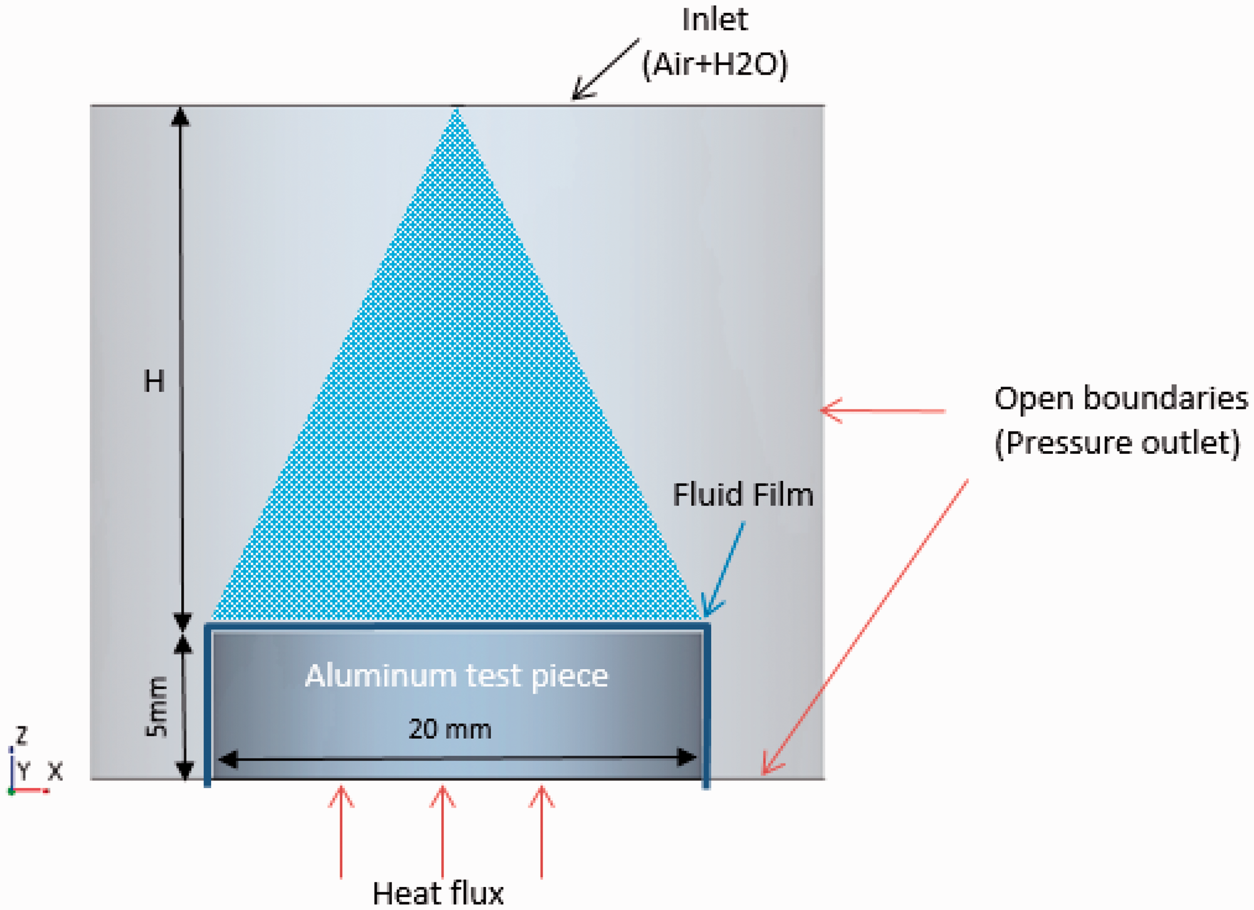
Results and discussion
The procedure described in ‘Numerical modelling’ section is now used to simulate Cases 1, 2, and 3 corresponding to the parameters given in Table 1. By allowing the simulation to run for a sufficiently long time, the surface temperature settles to a steady-state value. Because the mechanism of heat transfer during spray cooling is complex, and the characteristics of spray (namely the velocity of droplets, droplet size distribution, and droplet number density) have a strong influence on the heat transfer, it is difficult to independently vary each of the spray parameters. This has an impact on how the results are shown.
Figure 3 shows the predicted heat transfer coefficients for Cases 1, 2, and 3, which are in reasonable agreement with the experimental data
28
(i.e. within the range 10–20%). Moreover, in respect of the dependence of key parameters in spray cooling, Mudawar et al.
11
asserted that the spray mass flux, not the droplet velocity, is the dominant factor for achieving a particular heat transfer. Both the numerical predictions and experimental data shown in Figure 3 strongly support this assertion that spray mass flux is the dominant factor influencing the heat transfer. In fact, the heat transfer coefficient appears to be a linear function of the spray mass flux. In particular, the mean droplet velocity in Case 1 is much larger than those in Cases 2 and 3. The heat transfer coefficient for Case 1 is the smallest because the mass flux is smallest. This clearly demonstrates that spray mass flux, not the droplet velocity, is the dominant heat transfer factor in spray cooling, which is also consistent with the experimental findings in Wang et al.
32
and Freund et al.
33
Variation of heat transfer coefficient with mass flux.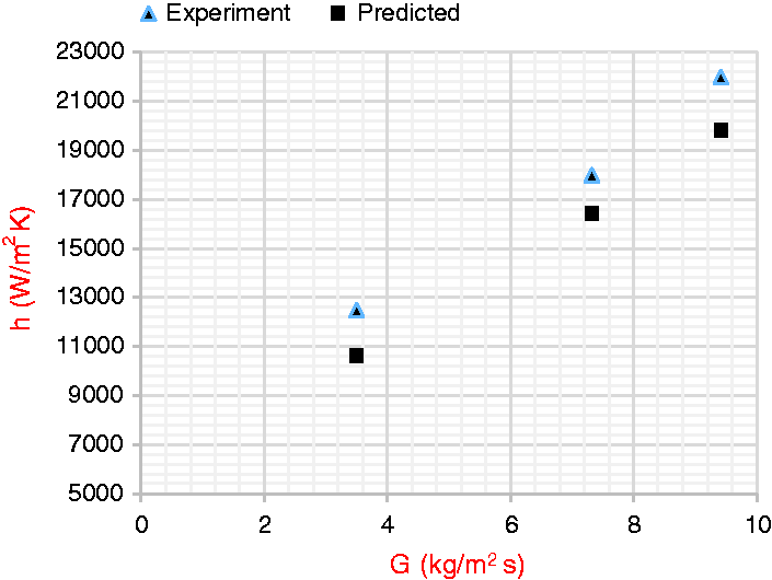
In the non-boiling (or the single-phase) regime, it has been demonstrated
7
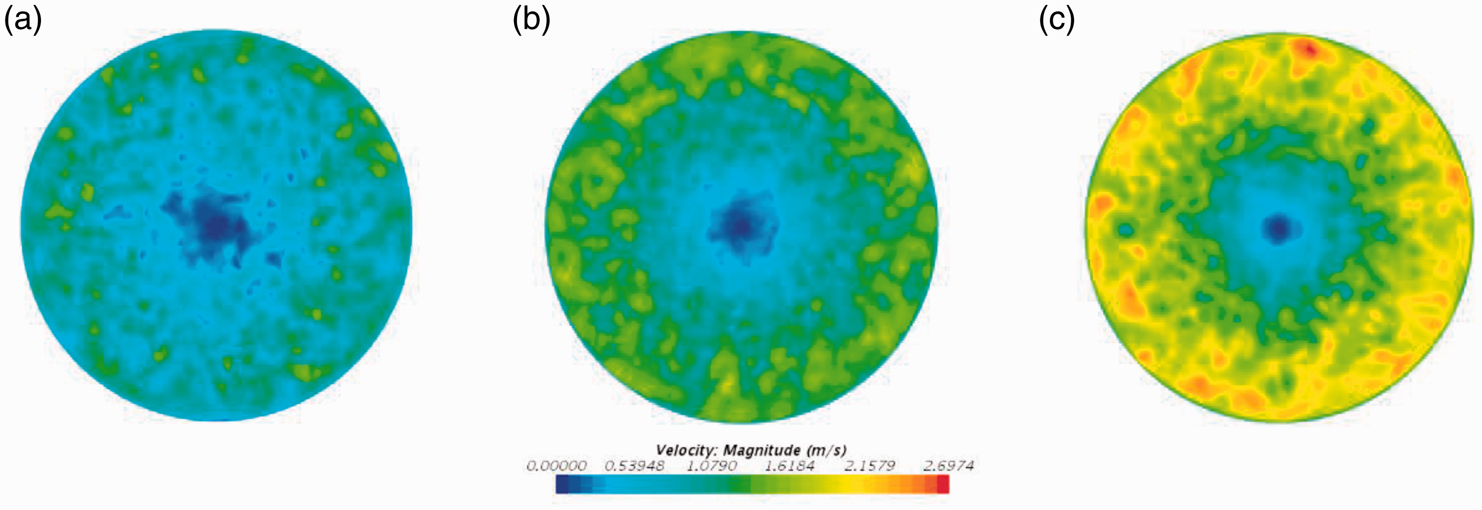
that single-phase convection, in a thin fluid film formed on the target surface, is the primary heat transfer mechanism. However, thin fluid film evaporation may occur, as evident in Figure 4, which shows a small amount of vapour near the targeted surface, playing only a minor role in the overall heat transfer. Compared with (conventional) forced convection, the enhanced heat transfer of spray cooling in the non-boiling regime is mainly derived from the discrete random nature of droplets disrupting the thin fluid film. The disturbances due to impinging droplets are clearly evident in Figure 5 which shows quite a random velocity distribution in the film. It can also be clearly seen that at larger spray mass flux, the velocity in the film increases correspondingly resulting in higher heat transfer.
Vapour mass fraction: (a) Case 1, G = 3.5 kg/m2s; (b) Case 2, G = 7.5 kg/m2s; and (c) Case 3, G = 9.5 kg/m2s. Film velocity: (a) Case 1, G = 3.5 kg/m2s; (b) Case 2, G = 7.5 kg/m2s; and (c) Case 3, G = 9.5 kg/m2s.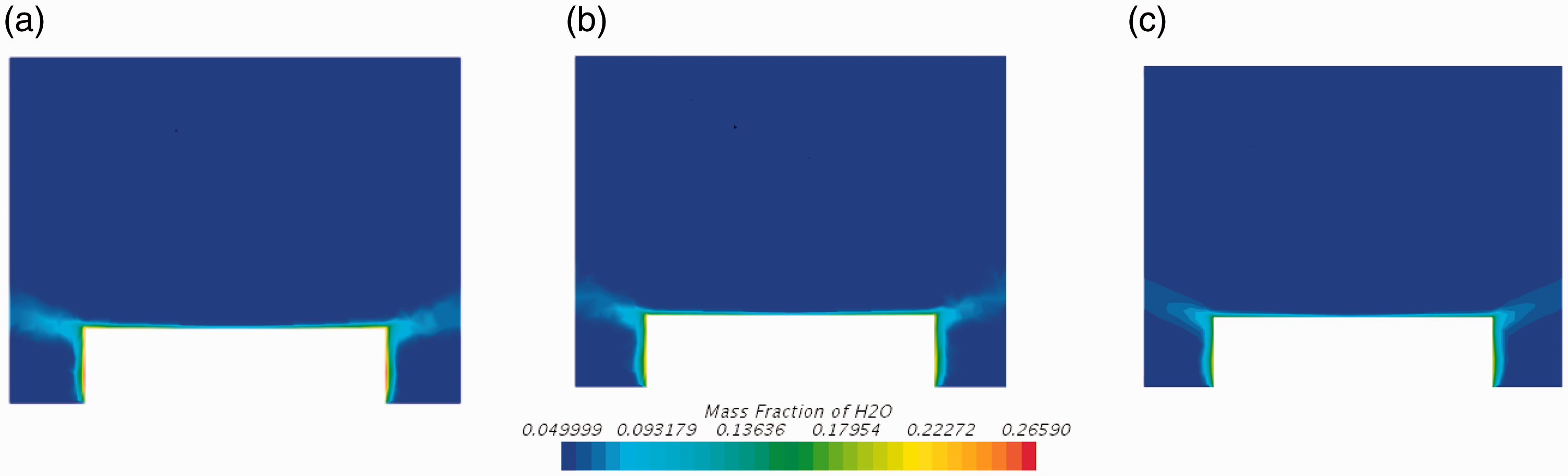
The temperature distributions on the targeted surface are shown in Figure 6. It is clearly evident (as expected) that the surface temperature decreases with an increase in spray mass flux. This is because the heat transfer coefficient is higher at larger spray mass flux as shown in Figure 3, i.e. more heat is removed from the surface leading to a lower surface temperature since the total heat flux supplied for all three cases is the same. Furthermore, it can be seen that the surface temperature near to the centre is slightly lower but increases slowly away from the centre, with a maximum temperature difference of less than 2℃ between the centre and the edge. The low temperature region on the targeted surface is likely to stem from more droplets impinging on this area. This argument is supported by the higher induced gaseous velocity in the centre region owing to droplet motion with higher mass flux, as shown in Figure 7.
Temperature on the target surface: (a) Case 1, G = 3.5 kg/m2s; (b) Case 2, G = 7.5 kg/m2s; and (c) Case 3, G = 9.5 kg/m2s. Induced velocity field in the chamber a central section: (a) Case 1, G = 3.5 kg/m2s; (b) Case 2, G = 7.5 kg/m2s; and (c) Case 3, G = 9.5 kg/m2s.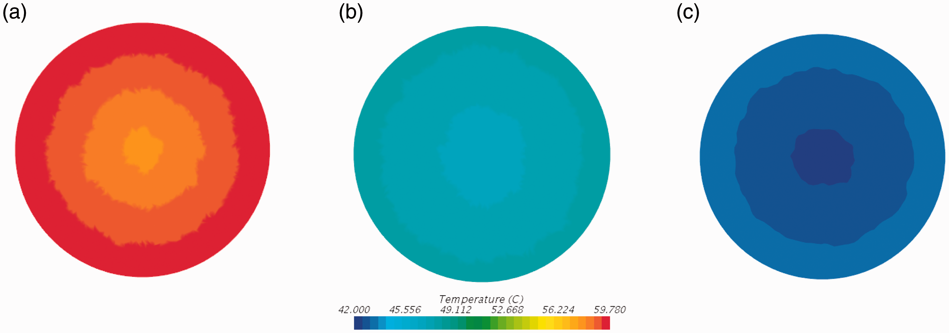
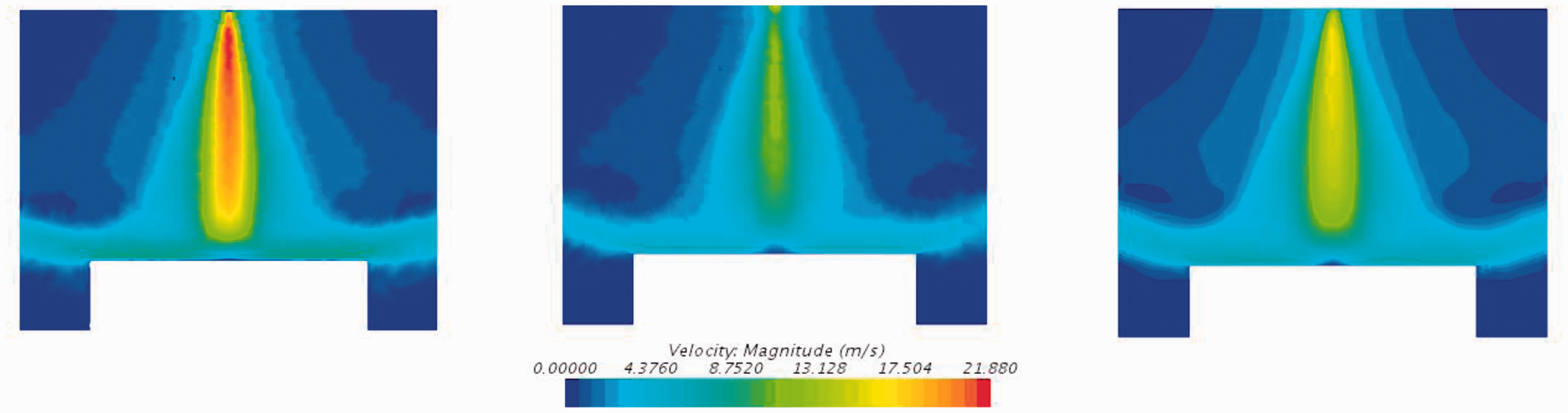
Figure 8 shows fluid film thickness on the target surface. It can be seen that the film thickness increases with the spray mass flux, i.e. a thicker film is formed on the target surface at higher spray mass flux. The velocity in the fluid film increases at higher spray mass flux as shown in Figure 5 but is not large enough to remove the increased fluid mass owing to more droplets arriving at the surface at higher spray mass flux resulting in an increase in film thickness. When the fluid film becomes ‘thick’, heat transfer from film evaporation reduces. But as shown in Figure 3 the heat transfer coefficient increases linearly with the spray mass flux. This strongly supports the argument that single-phase convection within the thin fluid film formed on the target surface is the primary heat transfer mechanism.
7
Fluid film evaporation only plays a minor role in the overall heat transfer as already discussed.
Film thickness: (a) Case 1, G = 3.5 kg/m2s; (b) Case 2, G = 7.5 kg/m2s; and (c) Case 3, G = 9.5 kg/m2s.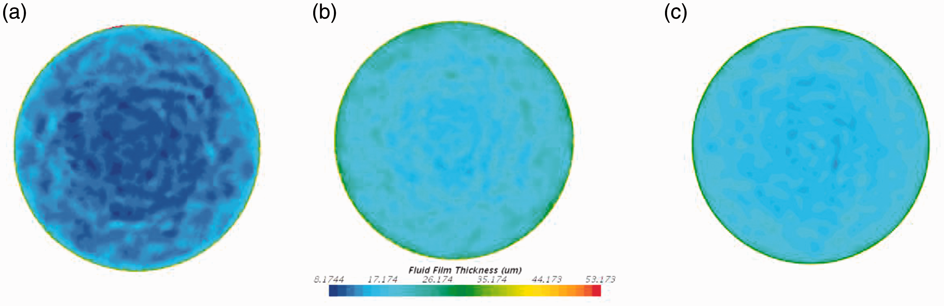
Conclusions
This paper has described a numerical study to predict heat transfer in the non-boiling regime between a hot surface and impinging full-cone spray of water at atmospheric pressure. Coupled CFD–CHT simulations have been used to predict the fluid flow and heat transfer for three different spray conditions. Spray break-up, wall impingement, film formation, and both droplet and film evaporation have been simulated in a Lagrange–Eulerian framework. The predicted heat transfer coefficients are in good agreement with published experimental data. The key findings of the study are as follows:
The spray mass flux, not the droplet velocity, is the dominant factor for heat transfer in spray cooling. Both numerical prediction and experimental data show heat transfer coefficient as a linear function of spray mass flux. Single-phase convection within the thin fluid film is the primary heat transfer mechanism whereas film evaporation plays only a minor role in the overall heat transfer. Heat transfer by spray cooling in the non-boiling regime stems mainly from the discrete random nature of droplets disrupting the thin fluid film. The velocity distribution in the film and the film thickness are far from uniform on the target surface owing to the disturbance caused by impinging droplets. The spatial variation in surface temperature within the film is almost uniform with a maximum difference of less than 2℃ between the temperature in the centre region and the temperature near to the edge. A lower temperature in the centre region stems from a greater number of droplets impinging on the centre.
Footnotes
Acknowledgements
The technical support is also acknowledged of colleagues at Ford Dunton UK and Dearborn USA, Denso Italy, and the Ricardo Technical Centre Shoreham, UK.
Declaration of conflicting interests
The author(s) declared no potential conflicts of interest with respect to the research, authorship, and/or publication of this article.
Funding
The author(s) disclosed receipt of the following financial support for the research, authorship, and/or publication of this article: The authors wish to acknowledge funding support for this project from the EPSRC under Contract Number: EP/M005755/1.