
Abstract
A review of published three-dimensional, computational fluid dynamics models for proton exchange membrane fuel cells that accounts for multiphase flow is presented. The models can be categorized as models for transport phenomena, geometry or operating condition effects, and thermal effects. The influences of heat and water management on the fuel cell performance have been repeatedly addressed, and these still remain two central issues in proton exchange membrane fuel cell technology. The strengths and weaknesses of the models, the modelling assumptions, and the model validation are discussed. The salient numerical features of the models are examined, and an overview of the most commonly used computational fluid dynamic codes for the numerical modelling of proton exchange membrane fuel cells is given. Comprehensive three-dimensional multiphase flow computational fluid dynamic models accounting for the major transport phenomena inside a complete cell have been developed. However, it has been noted that more research is required to develop models that include among other things, the detailed composition and structure of the catalyst layers, the effects of water droplets movement in the gas flow channels, the consideration of phase change in both the anode and the cathode sides of the fuel cell, and dissolved water transport.
Keywords
Introduction
In recent years, fuel cells have become an important clean energy technology, and thereby a serious contender to replacing some of the traditional power systems which rely on fossil fuels. Fossil fuels produce a significant amount of pollutants and they are rapidly depleting resources. Thus, it is becoming increasingly difficult to ignore the critical role that fuel cells can play in the different energy mix scenarios of many countries.
Besides their environmental advantages, in general, fuel cells offer many other advantages over conventional energy conversion devices. They directly convert chemical energy of the fuel into useful work, without requiring any thermodynamic cycle. Thus, their practical efficiency in direct electrical energy conversion can reach as high as 60%. 1
Proton exchange membrane (PEM) fuel cells which are the focus of this review article have high power density and operate at relatively low temperatures, which make them well suited for automotive power system, as well as power generation systems for buildings and portable electronics.
However, despite this, PEM fuel cell economics, especially the high capital and working expenses associated with their fabrication and testing, constitute a major obstacle to their rapid development. To tackle this issue, computational fluid dynamic (CFD) modelling and simulation can be used to rapidly gain important insights into PEM fuel cell working processes. These include fluid flow, mass and heat transfers, and chemical reactions inside the fuel cell, which can provide critical information needed for the optimization of PEM fuel cells.
Most reviews on PEM fuel cell CFD modelling provide a general discussion of a wide range of CFD models for PEM fuel cell. This review focuses on published 3D multiphase flow CFD models. The idea is to create a focused review, aiming at critically analysing the quality of the models meeting these criteria by discussing their strengths and weaknesses and identifying outstanding issues instead of conducting a broad historical overview of the published literature.
The review is organized as follows. The next section defines four basic concepts that are essential to understanding the subsequent sections. ‘Rationale for PEM fuel cell CFD modelling’ section gives the rationale for the use of CFD in PEM fuel cell modelling. ‘Literature 3D multiphase flow CFD models’ section reviews the literature’s PEM fuel cell 3D multiphase flow CFD models according to their areas of investigation. ‘Multiphase flow models and phase change’ section examines multiphase flow modelling and the implementation of phase change in the reviewed papers. ‘Numerical procedures’ section outlines a number of salient numerical features of the reviewed models. ‘CFD codes for PEM fuel cell modelling’ section provides an overview of the most commonly used CFD codes for PEM fuel cell modelling. ‘Summary and outlook’ section summarizes the review highlighting future trends in the PEM fuel cell modelling.
Essential concepts
Transport phenomena
The study of transport phenomena is a multidisciplinary subject that draws on science and engineering concepts as diverse as fluid mechanics, mass transfer, heat transfer, and electromagnetism. Each one of these concepts deals with a specific transport phenomenon. The transport of momentum is dealt with in fluid mechanics, the transport of mass of various chemical species is considered in mass transfer, the transport of heat is explained in heat transfer, and the transport of charges is depicted in electromagnetism. 2
The physical quantities that are transported within a PEM fuel cell are mass, momentum, chemical species, thermal energy, electrical current, and ionic current. To describe the transport of these physical quantities in the different components, the conservation laws in terms of rate of accumulation and generation/consumption are used.
Generic governing equations for PEM fuel cell models. 3
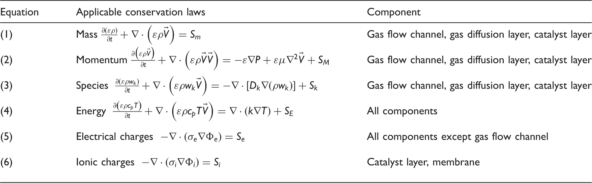
PEM: proton exchange membrane.
Multiphase flow
Multiphase flow refers to fluid flows consisting of two or more phases, with a phase being a solid, a liquid, or a gas that coexist with another solid, liquid, or gas.
The most common types of multiphase flows are the two-phase flows and the three-phase flows. The two-phase flows include gas–liquid flow, gas–solid flow, liquid–liquid flow (e.g. oil–water mixtures in pipelines), and liquid–solid flow. The three-phase flows encountered in engineering applications include gas–liquid–solid flow, gas–liquid–liquid flows (e.g. gas–oil–water flows in oil recovery systems), and solid–liquid–liquid flows (e.g. immiscible liquid–liquid reaction in which a solid phase is formed).
The different phases forming a multiphase flow are usually separated by an identifiable boundary which constitutes the interface between two phases. The interfaces are where the transfer of material, momentum, and energy may occur between the phases. The modelling of multiphase flows is immensely challenging and often requires a sound understanding of the various multi-physics phenomena that are involved.
In PEM fuel cells, multiphase transport originates from the production of liquid water by the oxygen reduction reaction and the phase change processes (evaporation and condensation).
CFD
CFD is a sub-discipline of fluid dynamics that employs a set of highly sophisticated numerical methods and algorithms to solve and analyse problems of fluid dynamics and beyond. 4 The problem under consideration is usually formulated mathematically using partial differential equations.
Since the CFD method is based on computational analysis, before any of the CFD numerical methods and algorithms can be used to compute practical numerical solutions, these must be translated into a computer program often referred to as CFD codes. CFD codes are usually written in a high-level computer programming language such as C or C++. 5
In general, a CFD-based analysis is performed in five major steps: (1) problem definition, (2) mathematical model formulation, (3) pre-processing and mesh generation, (4) solving, and (5) post-processing. Some of these steps must be repeated multiple times in order to obtain the desired results.
The problem is usually defined in its simplest possible form that still accurately describes the actual real world system under consideration. The mathematical model is used to formulate the problem mathematically, describing the details of the flow. The pre-processing and mesh generation sets the various fields of interest before the start of the simulation and discretize the flow domain into computational mesh consisting of volumes or cells. In the solving step, the differential model gets replaced by a system of linear algebraic equations which are solved using algorithms. Finally, the post-processing offers the means to visualize the simulation data in order to inspect the details of the flow.
PEM fuel cell
The basic operating principle of fuel cells which consist of reversing water electrolysis to generate electricity from hydrogen and oxygen was discovered by William Grove in 1839. 6 Although the technology has matured significantly, this same principle still defines the operation of current PEM fuel cells.
Thus, simply put, a PEM fuel cell is an electrolytic cell that runs on hydrogen and oxygen. Its working process can be a multiphase reaction process, generating heat while converting chemical energy into electrical energy without producing any greenhouse gases.
Working principle
There are three key components that form a PEM fuel cell. A solid polymer membrane sandwiched between two electrodes, a negatively charged electrode (anode), and a positively charged electrode (cathode). Both the anode and the cathode contain a catalyst layer (CL), a gas diffusion layer (GDL) with micro-porous layers, and a bipolar plate (BP) with gas flow channels (GFC). The schematic representation of the operation of a single cell is shown in Figure 1.
An illustration of PEM fuel cell operation. PEM: proton exchange membrane.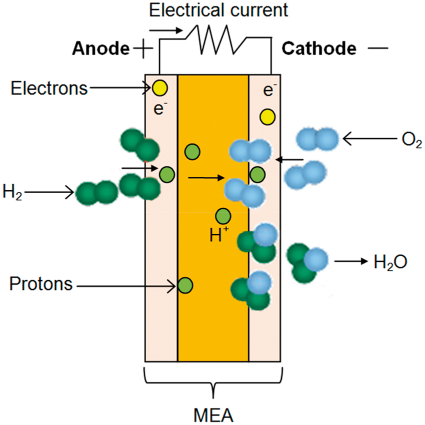
The cell is fed with hydrogen at the anode side and oxygen at the cathode side. These two gases subsequently react together to provide chemical energy for conversion to electrical energy. However, due to the inefficiency in the energy conversion, a portion of chemical energy is converted to waste heat instead of electricity. 7
The overall electrochemical reaction as shown in equation (9) is the sum of the reactions occurring at the electrodes (anode and cathode), given in equations (7) and (8), respectively.
At the anode

At the cathode

Overall

Electrical current is created by the movement of electrons, resulting from the splitting of hydrogen into protons and electrons at the surface of the catalyst. The electrons travel from the negatively charged anode side to the positively charged cathode side, following an external circuit that connects the two electrodes through a load, whereas the protons travel through the membrane. At the catalyst of the cathode side, they meet with oxygen that is fed on that side to form water and produce heat. 3
The product water may be in vapour or liquid form. Liquid water formation depends on the water vapour saturation pressure and temperature. The presence of excess liquid water can be problematic in PEM fuel cells, as it can create a phenomenon known as flooding. Flooding has a negative effect on mass transfer. Hence, to protect the integrity of the fuel cell, the product water and waste heat generated during the operation must be continuously removed.
Liquid water may be transported out of the cathode CL through the cathode GDL and then the cathode GFCs. Fuel cells may be fitted with cooling units at the BPs to deal with the waste heat.
The operating principle of PEM fuel cells may well be simple and basic, but the phenomena occurring during their operation are highly complex. They involve electrochemical reactions, species and charge transport, mass transfer, heat transfer, and multiphase flows. Sound knowledge of these multi-physics phenomena is therefore critical in PEM fuel cells optimization.
Components
As described in ‘Working principle’ section, a single cell consists of a polymer electrolyte membrane sandwiched between two electrodes. As illustrated in Figure 2, each electrode has a BP with GFCs, a GDL, and a CL.
Schematic of a single-cell PEM fuel cell with straight channels. PEM: proton exchange membrane.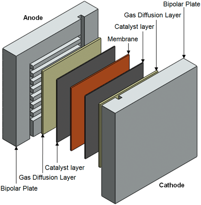
BP
The BPs (also known as the collector or separator plate) are electrically conductive plates which separate the gases in adjacent cells in the stack while connecting the individual cells electrically. They provide housing for the GFCs and a structural support for the stack. 3 The heat generated within the membrane electrode assembly (MEA) is transferred to the cooling system through the BPs. Electrons are transferred from/to the GDLs to/from the BPs.
GFCs
The GFCs in the BPs provide the pathways for the transport of the reactant gases to the GDL and product water out of the electrodes. To ensure an even distribution of the fuel and oxidant within the cell, different flow field designs with different advantages exist. The most commonly seen are straight parallel, serpentine, and interdigitated flow fields.1,8
GDL
The GDLs are porous media located between the BPs and the CLs. Thus, not only they allow uniform distribution of the reactants across the surface of the CLs, but they also provide an electrical connection (electrons transport) between the CLs and the BPs, as well as creating a structural support for the CLs. 1
CL
The CLs are the thin layers attached to both sides of the membrane. It is on the surface of the CLs that the electrochemical reactions that convert chemical energy in electrical energy take place within a PEM fuel cell.
Membrane
The membrane is a solid polymer electrolyte that separates the anode from the cathode in a PEM fuel cell. In other words, it is an electronic insulator that is also impermeable to the reactant gases but allows protons transport. Thus, the desired characteristics of a PEM fuel cell membrane are good electronic insulation, good separation of hydrogen in the anode side and oxygen in the cathode side, and high proton conductivity.
Rationale for PEM fuel cell CFD modelling
As mentioned in ‘CFD’ section, CFD is foremost a numerical method that is used to solve partial differential equations of fluid dynamics. These partial differential equations are non-linear and analytical solutions can only be obtained in a few simple special cases. In order to obtain solutions to most problem of practical interest, a CFD implementation is therefore necessary. 5
This is applicable to PEM fuel cells as electrochemical devices, because the motion of the reactant gases and product water is governed by non-linear conservation equations derived from first principles of fluid mechanics making analytical solutions only possible in 1D and highly simplified cases.
In addition to the analytical challenge of solving non-linear equations in PEM fuel cell models, the cost of manufacturing fuel cells and the cost associated with their performance testing often render many experimental techniques uneconomical. Thus, much research work on fuel cells tries to improve the cell performance by increasing its efficiency while decreasing manufacturing and testing costs, through CFD techniques.
Indeed, over the past decade or so, CFD techniques have been employed extensively to model PEM fuel cells. The approach is based on numerical approximation of the solutions of the conservation equations of mass, momentum, energy, current, and species transport on a computational domain that is discretized using the finite-volume, finite-difference, or finite-element schemes.
Through CFD analysis, a deeper understanding of the problem under consideration can be obtained. In fact, the importance of CFD modelling and simulation of fuel cell working processes has been repeatedly addressed throughout the literature. For instance, CFD can help understand water management within a PEM fuel cell. Recalling ‘Working principle’ section, water transport is one of the central issues in PEM fuel cell technology.
CFD has many other important applications in PEM fuel cell system analysis and is consequently of immense technological and economic significance. Nevertheless, due to the complexity of the multi-physics phenomena occurring in a complete fuel cell, some simplifying assumptions are still necessary in order to create a numerically tractable model of a complete fuel cell.
Literature 3D multiphase flow CFD models
The past few decades have seen the number of published modelling and simulation work on PEM fuel cells increased dramatically. This has essentially been made possible by recent advances in computational techniques and the availability of high-performance computing resources.
The majority of the literature’s 1D computational PEM fuel cell models consider the direction orthogonal to the membrane, with varying degrees of complexity and details. The computational 2D models not only treat the transport phenomena that occur inside the fuel cell in the direction orthogonal to the membrane, but they also consider another additional direction, usually either the dimension along the GFC or that perpendicular to it.
Although the pioneering 1D models and subsequent 2D models have significantly contributed to the advancement of PEM fuel cell modelling, these models can only be used for particular phenomena in PEM fuel cells due to the 3D nature of the transport processes occurring in a PEM fuel cell. Consequently, they are not suitable for parametric studies or optimization of fuel cell designs. 9 Moreover, the transports of mass, heat, and charges in porous structures are major issues for these models.
To accurately predict cell performance, a realistic 3D description of the cell geometry is necessary. Thus, 3D computational models have been developed to better understand the phenomena occurring within PEM fuel cells and then predict their performance though a full 3D description of a complete cell or a fuel cell stack requires a considerable computational effort. Three-dimensional models consider effects in both across and along the gas flow channel, in addition to the direction normal to the membrane.
This review intends to examine the majority of the literature’s PEM fuel cell 3D multiphase flow CFD models though it is likely that it may not include all of the published models. The focus is placed on comprehensive models that are relevant in the context of the present review work. The time frame is set to cover any of such models published through the second quarter of 2016, as of the time the present review has been completed. Thus, only the models that satisfy all criteria of 3D, multiphase flow and CFD-based modelling are included.
A direct comparison of the different models is problematic because they vary in their approach and complexity to modelling multiphase flow and phase change, as well as their validation methods. Also, one model may be well suited for specific operating conditions in a specific region, whereas another one would not be. Therefore, the majority of this review delves into discussing the advantages and potential drawbacks of each model.
The bulk of the models treat phenomena such as water and reactant transport, electrochemical reactions, species and charge transport, mass transfer, heat transfer occurring during the cell operation, with the effects of geometry or operating conditions.
Thus, depending on the characteristics of the phenomena being investigated, and the level of details included, the models can be divided into three distinct groups: models for transport phenomena, models for geometry or operating condition effects, and models for thermal effects.
The pie chart in Figure 3 shows that transport phenomenon is the most studied subject in the reviewed articles followed by geometry or operating condition effects and then thermal effects. This trend can somehow be expected since the 3D architecture of PEM fuel cells makes transport phenomena within them a 3D problem inherently. Moreover, liquid water transport and its effects in the different fuel cell components continue to capture the attention of many PEM fuel cell researchers.
The reviewed papers according to their areas of investigation.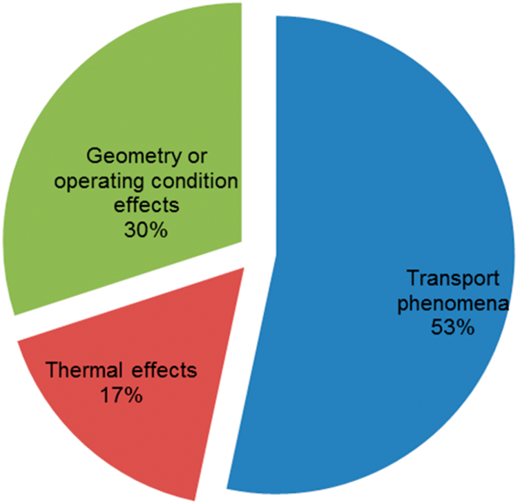
As was pointed out in previous paragraphs, 3D models are more complete and they can be used for design and optimization purposes. The focal point of the literature models for geometry or operating condition effect has been the design of the flow field; namely, the influence of various flow-field designs on cell performance. The majority of the models for thermal effects are concerned with the temperature distribution inside the cell and the effects of this on the fuel cell performance.
Summary of the reviewed research papers.

Modelling assumptions
Regardless of the type of multiphase flow model being used, it is often necessary to make some modelling assumptions in order to simplify the problem under consideration and thereby facilitate its numerical implementation without reducing the accuracy of the model. Indeed, these assumptions must be based on well-established theories and practices.
Some commonly used assumptions in PEM fuel cell modelling are steady state, ideal gases, laminar and incompressible gas flow, local thermal equilibrium, and isotropic and homogeneous components materials. For the state of water produced by electrochemical reaction in the cathode CL, both vapour and liquid assumptions are used.
Besides these assumptions, there are many other component and operating condition-specific simplifying assumptions that are also used. Some of these may, however, limit the capability of the model or even lead to erroneous results.
An example is the isothermal assumption, which means that the transport of thermal energy given by Table 1, equation (4) is not solved. This can produce results that are not physically representative when phase change is accounted for. In fact, it has been shown that the impact of temperature distribution on the amount of water that undergoes phase change is very significant. 41
Another example is considering the CL as an interface without thickness. Although this assumption greatly simplifies the CL modelling and facilitates its numerical implementation, it may however introduce inaccuracy due to the neglected contribution of ionic resistance, particularly at low humidity. 20 Furthermore, experimental results suggest an agglomerate structure for the CL,42,43 and it has been shown that agglomerate-type models agree better with the physical picture of reactant transport processes in the CL and they best fit the experimental data.44–46
Also, many models neglect the influences of the motion of liquid water in the GFCs. As pointed out in ‘Components’ section, the GFCs in the BPs deliver reactant gases and help remove product water. This results in gas–liquid two-phase flow in the GFCs. Consequently, the reactant gases transport can be hindered when considerable amount of liquid water accumulate in the channels leading to poor cell performance. Thus, the effects of liquid water in the GFCs should be accounted for.
Models for transport phenomena
Berning and Djilali 11 presented a model that accounts for the major transport processes, as well as phase change. The results show that phase change exists in both the anode and cathode sides of the fuel cell. The anode and cathode transports are however decoupled in this model, the CLs are treated as thin interfaces, and liquid water transport by electro-osmotic drag is neglected.
Mazumder and Cole 12 modified a model originally proposed by Wang and Cheng 47 by adding an additional governing equation for the formation and transport of liquid water. Although the numerical predictions of the cell performance quantitatively over-predict experimentally measured polarization in the high current density regime, the results nonetheless indicate that at critical current density, the saturation levels can exceed 50% and are highest in the cathode.
Schwarz and Djilali 16 incorporated the 1D multiple thin-film agglomerate catalyst model of Baschuk and Li 48 into a comprehensive 3D model to investigate the effects of transport limitations on cell performance in the CLs. It was found that transport limitations and ohmic losses in the CLs have substantial negative effects on the fuel cell performance. The model however does not consider the effects of liquid water in the GFCs.
Ren et al. 19 developed a gas–liquid two-phase flow and transport model to address the need to account for all major flow and transport phenomena with an emphasis on various factors influencing cell performance. The results show that substituting the air with oxygen and increasing the inlet gas velocity while decreasing the thickness of the membrane and the width of the rib will improve the cell performance. This model assumes isothermal condition and water phase change is only considered in the cathode CL. It has been shown that phase change exists in both the anode and cathode sides of the fuel cell. 11
Wang 20 investigated multiphase flow, species transport, and electrochemical processes and their interactions using a two-phase flow model but with the assumption of isothermal condition. The results indicate that two-phase flow can occur in both the anode and cathode diffusion media, with the two phases coexisting at low humidity. This model does not however account for water phase change.
Wang et al. 21 implemented a two-phase flow model to understand three critical issues in the channels: liquid water build-up towards the outlets, saturation spike in the vicinity of flow cross-sectional heterogeneity, and two-phase pressure drop. The results reveal that liquid water builds up quickly at the entrance region of the gas channel with the predicted saturation reaching as high as 20%. Water trapping around the geometrical heterogeneity was also found. This model is limited to a single channel that is not integrated into a full cell model.
Berning et al. 22 presented a multiphase model that describes the flux of liquid water through the porous media and into the GFCs. In this model, the overall level of the predicted liquid saturation depends predominantly on the fraction of hydrophilic pores which can be accounted for in the irreducible saturation. This can be a limiting factor for the accuracy of the predictions since the results show that the irreducible saturation has an important impact on the limiting current density. Also, the interaction between the gas and liquid phases in the GFCs is not considered.
Schwarz and Beale 23 implemented a comprehensive model to perform multiphase transport calculations and to investigate the effects of ohmic losses and transport limitations on current density distributions for the cell design. It was found that the current density in the cathode CL is concentrated near the gas channels inlets due to the resistances of air and flooding to oxygen transport. The model however neglects the effects of liquid water in the gas channels.
Wu et al. 27 developed a model that fully couples the major transport processes and performed both liquid and vapour production modelling. The results show that the dynamic response of the fuel cell in vapour production modelling is significantly overestimated compared to liquid production modelling. A potential drawback of this model is that it was validated against experimental data that were obtained using a different type of membrane material.
Cordiner et al. 28 extended the validity of the existing isothermal two-phase model of Cordiner et al.49,50 by implementing a decoupled GDL model into a CFD solver to describe the effect of the representation of liquid water flooding on cell performance. It was concluded that flooding must be treated as a 3D phenomenon, as it has different impacts in different regions of the fuel cell.
Fink and Fouquet 29 presented a model accounting for the major transport phenomena and their coupling. The simulation results show that liquid water mainly accumulates below the channel lands where condensation takes place resulting in liquid water production. A shortcoming of this model is that it does not study the influence of liquid water droplet movements on performance in the GFCs.
Sun et al. 32 introduced Kirchhoff transformation technique and a combined finite element-upwind finite volume approach for efficiently achieving a fast convergence and reasonable solutions for a two-phase transport model. The results demonstrate the efficiency of the numerical technique used. The model used is, however, isothermal and does not take into account water back diffusion effect through the membrane.
Hossain et al. 34 developed a two-phase model to investigate the transport of species in the GDL considering liquid water saturation. It was found that higher cell performance can be achieved by optimizing the permeability of the GDLs. The main limits of this model are the assumption of isothermal condition and 1D water transport in the membrane by back diffusion only.
Jiang and Wang 35 developed a two-phase flow model by fully coupling species transport, heat transport, and electrochemical processes to investigate the formation and the transport of liquid water. It was found that liquid water build-up in the cathode channel dominates liquid water spreading inside the cell and dictates the performance of the fuel cell.
Ferreira et al. 38 used the volume of fluid (VOF) method to numerically investigate two-phase flow in the anode gas channel and analyse water movement. The results reveal that water moves as films for hydrophilic channel walls, whereas it moves as a droplet when the channel walls are hydrophobic. This model is isothermal and phase change or electrochemical reactions are not considered.
Jo and Kim 39 also used the VOF method to numerically investigate the dynamics of liquid water emerging from a micro pore on the GDL into the GFC. It was concluded that with decreased GDL surface contact angle, droplets from the outer and inner pores move along the side walls and the movement of droplets from the centre pore shows complex patterns. Furthermore, as the hydrophobicity of the side and top walls increases, the GDL surface water coverage ratio increases while the water volume fraction decreases. This model is isothermal and phase change or electrochemical reactions are not considered.
Models for geometry or operating condition effects
Al-Baghdadi and Al-Janabi 15 conducted an optimization study using a multiphase model that incorporates the significant physical processes and the key parameters affecting cell performance. The results show that the model is capable of accurately quantifying the impacts of operating, design, and material parameters on the fuel cell performance. The main limits of this model are the treatment of the CL as a thin interface and the consideration of phase change in the GDLs only.
Jang et al. 18 developed a model with conventional flow-field designs to study the influences of flow-field designs on fuel utilization, water removal, and cell performance. It was found that the cell performance of the serpentine flow field is the best followed by the Z-type flow field and the parallel flow field. The model assumes isothermal condition and does not account for the motion of liquid water.
Schwarz and Djilali 24 used the multiphase flow model of Schwarz and Djilali 16 to explore the implementation of spatially distributed catalyst loadings in all three directions for both the anode and the cathode. The results show that at high current densities, the over-potential variations in the anode and the cathode CLs are fairly large. This study does not examine the use of variable composition for the CL.
Berning et al. 25 extended a previously published model by Berning et al. 22 in order to account for phase change kinetics and to conduct a comparison between the interdigitated flow-field design and a conventional straight channel design. It was found that the interdigitated flow field yields higher and more uniform oxygen concentration as well as a lower overall liquid saturation at the CL. The interaction between the gas and liquid phases is, however, not considered in this model.
Yuan et al. 26 developed a multiphase model to predict the effects of operating parameters such as operating pressure, cell temperature, relative humidity of reactant gases, and air stoichiometric ratio on cell performance. The results indicate that increased operating pressure and temperature can enhance the cell performance. Moreover, it was found that the best performance occurs at moderate air relative humidity while hydrogen is fully humidified.
Kang et al. 30 used a multiphase porous cathode side model to study liquid water flooding in an interdigitated flow-field design. The results reveal the existence of a so-called liquid water avalanche phenomenon in this type of cathode design. Also, the existence of three distinct phases for liquid water flooding process is found; these are porous layer phase, channel phase, and drainage phase. This model is limited to the cathode side only and heat transfer and electrochemical reactions are not considered. Furthermore, the model does not account for water phase change.
Chiu et al. 31 presented a two-phase transport model with parallel, interdigitated, and serpentine flow-field designs to investigate the effects of flow-field design on cell performance and water removal. The results show that the cell performance with parallel and serpentine flow fields can be improved by reducing the height or the width of the channel; of the three flow fields, the interdigitated flow field is the most effective on liquid water removal. Potential drawbacks of this model are the assumption of isothermal condition and the use of a highly simplified multiphase model.
Mancusi et al. 36 used a combined multi-fluid and VOF approach to study two-phase flow in a tapered channel design. The results show that tapering the channel downstream enhances water removal due to increased airflow velocity.
Choopanya and Yang 37 developed a multiphase model to investigate the effect of the parallel and the serpentine flow-field geometries on the cell performance under both steady-state and transient operations. It was found that in the steady-state run, the average current density increases with the use of a serpentine flow field due to superior water removal ability. For the transient operation, the use of a serpentine flow field combined with dry reactant gases help the removal of product water and accelerate the transport of reacting species to the reaction site. This model does not however account for water phase change, and the dynamics and movement of liquid water are not studied.
Khazaee and Sabadbafan 40 developed a two-phase model to investigate water management and the performance of PEM fuel cell with 1-serpentine and 4-serpentine channels flow-field configurations at different operating conditions. The results show that under identical conditions, the 4-serpentine configuration outperforms 1-serpentine configuration. However, the effects of liquid water in the channels are not studied in detail.
Models for thermal effects
Shimpalee and Dutta 10 modified a model already presented by Dutta et al. 51 by including the energy equation to predict the temperature distribution inside a straight channel and the effect of heat produced by the electrochemical reactions on cell performance. The predictions show that the cell performance depends not merely on geometric or operating condition parameters but also on the temperature rise inside the fuel cell. A shortcoming of this model is that it neglects the heat generated by ohmic resistance in the porous media and the membrane.
Coppo et al. 13 used the 3D implementation of a previously developed 2D model by Siegel et al.44,52 to analyse the effects of temperature on the cell operation. It was found that higher temperature positively affects the reaction kinetics. However, only the heat source due to phase change in the cathode CLs is added in the energy equation.
Matamoros and Bruggemann 14 developed a model that specifically computes water and heat management. The simulation results show that the operating temperature has negative effects on the hydrating properties of the membrane. The only heat sources included in the model are Joule heating in the membrane and latent heat in the cathode.
Shimpalee et al. 17 extended the existing model of Shimpalee et al.53,54 to include energy and water phase change equations for studying phase change and heat transfer. It was found that a single-phase and isothermal model shows higher current overshoot than a water phase change and non-isothermal model. The model does not account for the heat sources due to ohmic resistance in the porous media and the membrane.
Cao et al. 33 presented a two-phase model to investigate amongst other things the interaction between water and thermal transport processes, and different boundary temperature of flow plate. The results show that the boundary temperature greatly affects the cell temperature distribution and indirectly influences water saturation distribution. The model however neglects liquid saturation in the channels.
Model validation
Validation is an essential aspect of any CFD-based analysis. During the validation process, the simulation results are compared with known experimental data or the results from previous numerical models.
Almost all of the models listed in Table 2 have been validated using some kind of experimental data. These include a detailed comparison of the predicted polarization curve or V–I curve with experimentally measured one. A comparison of the simulation results with the results from previous models was also performed in a few cases. Overall, the results were found to be in good agreement with either experimental or previous model results.
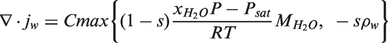
Multiphase flow models and phase change
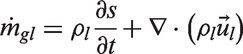
As described in ‘Multiphase flow’ section, in PEM fuel cells, the production of liquid water by the oxygen reduction reaction and the phase change process are the origin of two-phase transport. The gas phase has multi-components (hydrogen and water vapour in the anode side; oxygen, nitrogen, and water vapour in the cathode side), while the liquid phase consists of only pure water.
In the reviewed articles, multiphase flow is modelled using the multi-fluid and multiphase mixture approaches essentially although the VOF model as well as some highly simplified models such as the moisture diffusion model, the porosity correction model, and a model in which the liquid phase is treated as a component of the gas phase is also used. Among other things, the multi-fluid model requires the specification of phase change kinetics, whereas local equilibrium between the gas phase and the liquid phase is inherently assumed in the multiphase mixture model. For more details on these topics, the reader is referred to the reference texts by Sunden and Faghri 55 and Wang et al. 7
Summary of multiphase flow models and implementation of phase change.

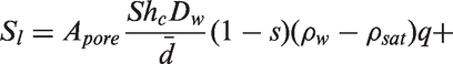
Multi-fluid model
The multi-fluid approach of multiphase flow modelling consists of solving a set of conservation equations for mass and momentum for each phase separately. The two phases are usually coupled through the relative permeability and the phase change terms. The following are generic steady-state mass and momentum conservation equations in the porous media
Mass

Momentum


The multi-fluid approach best suits high saturation conditions, as these demand a greater liquid resolution. The model can resolve complex liquid motion and accounts for the convection of liquid by the gas. As for the disadvantages, the multi-fluid model requires a high number of variables and the coupling of the phases can lead to unstable models. 55
Multiphase mixture model
As its name suggests, in the multiphase mixture model, the phases are considered to be mixed; and thus, a single set of conservation equations for the phase mixture is solved. Phase equilibrium is assumed and the mixture quantities such as density and so forth, as well as the relative velocity among different phases are evaluated subsequently. The mass conservation and momentum equations for the mixture read 7
Mass
Momentum
The mixture density and velocity are defined as
7
The mixture species conservation equation is expressed as
7
The multiphase mixture approach is best used when the gas phase pressure dominates the liquid phase pressure or when high capillary numbers are encountered. This approach reduces the number of variables and can effectively model the influence of the gas pressure on the liquid. However, large number of mixture quantities need to be calculated and the model may have convergence issues at higher saturations. 55
Moisture diffusion model
The moisture diffusion model is based on the unsaturated flow theory. It is used to determine the transport of liquid water when the only driving force is the capillary pressure.
The transport equation of liquid water in the moisture diffusion model is written as
55
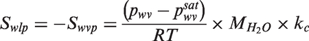
The moisture diffusion model is well suited for low capillary numbers and when surface tension is the dominant force on the liquid. It only requires one additional equation to an existing single-phase model. A limitation of this approach is that the influence of the gas pressure on the liquid is not accounted for. 55
Porosity correction model
In the porosity correction model, the transport of liquid water is not modelled. Instead, it is assumed that liquid water fully occupy some pores of the porous media, meaning that no pore presents coexistence of gas and liquid water. Thus, the volume fraction open to the gas phase is determined by
55
This approach is best used in low relative humidity, very small pores, and low current density conditions. It does not require any additional transport equations over the single-phase model. A major drawback of this model is that it does not account for the motion of liquid water. 55
VOF model
VOF is a method for locating and advecting the interface in a gas–liquid two-phase flow. The method proceeds by reconstruction of the interface shape and then advection of the reconstructed interface in a given velocity field. 56 A single momentum equation such as the one given by Table 1, equation (2) is solved and the volume fraction of each of the fluids is tracked throughout the domain.
The VOF method can capture the effects of surface tension making it well suited for micro-channel flows in which surface tension is an important and sometimes dominant force. A limitation of the VOF technique for multiphase flow modelling is that it only deals with the interface of the liquid and gas. The entire fuel cell multiphase flow computation is still dealt with by a CFD package using the multi-fluid or the multiphase mixture model.
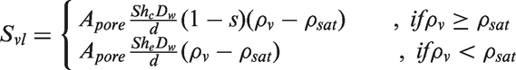
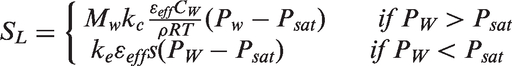
Phase change
In a thermodynamic system, the state of matter can change from one phase to another. This transformation process is known as phase change.
In PEM fuel cells, water may exist as three different phases: water vapour, liquid water, and dissolved water. Since this type of fuel cell operates at relatively low temperatures (50–100℃), phase change is thus frequently encountered.
In fact, liquid water present within the cell can evaporate into water vapour, and conversely, water vapour can condense into liquid water. Also, phase change occurs from water vapour to dissolved water (water uptake into the polymer phase of the CL) and from dissolved water to liquid water (water released from the polymer phase of the CL). In many phase change models, the occurrence of water phase change is determined by the gas-phase humidity.
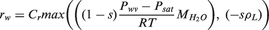
In the selected papers, phase change kinetics is mainly implemented in the form of evaporation and condensation. The total amount of water undergoing evaporation depends on the level of undersaturation and the surface area of the liquid phase. Condensation is fundamentally different from evaporation as it can occur on any hydrophilic surface. Water vapour condenses into liquid water droplets when the local water vapour pressure exceeds the local saturation pressure.
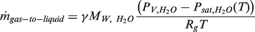
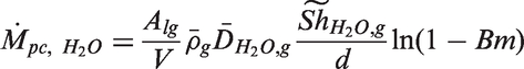
In the majority of the articles reviewed, dissolved water resulting from the transport of protons in the CLs and the membrane is not considered as a separate water phase. Consequently, dissolved water related-phase change processes are neglected; dissolved water is simply treated as part of the liquid phase.
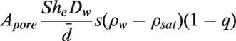
However, since the protons produced in the CL are assumed to be dissolved in water and are transported along with the water molecules through diffusion, due to a concentration gradient between the anode and the cathode, and electro-osmotic drag; dissolved water should be considered as a separate water phase, and thus dissolved water-related phase change processes should be treated separately. The governing equation of dissolved water transport is written as
52

The total rate of water vapour transfer into dissolved water is calculated as follows
46

The total rate of dissolved water transfer into liquid water is calculated as follows
46

Numerical procedures
Summarized numerical features of the reviewed papers.
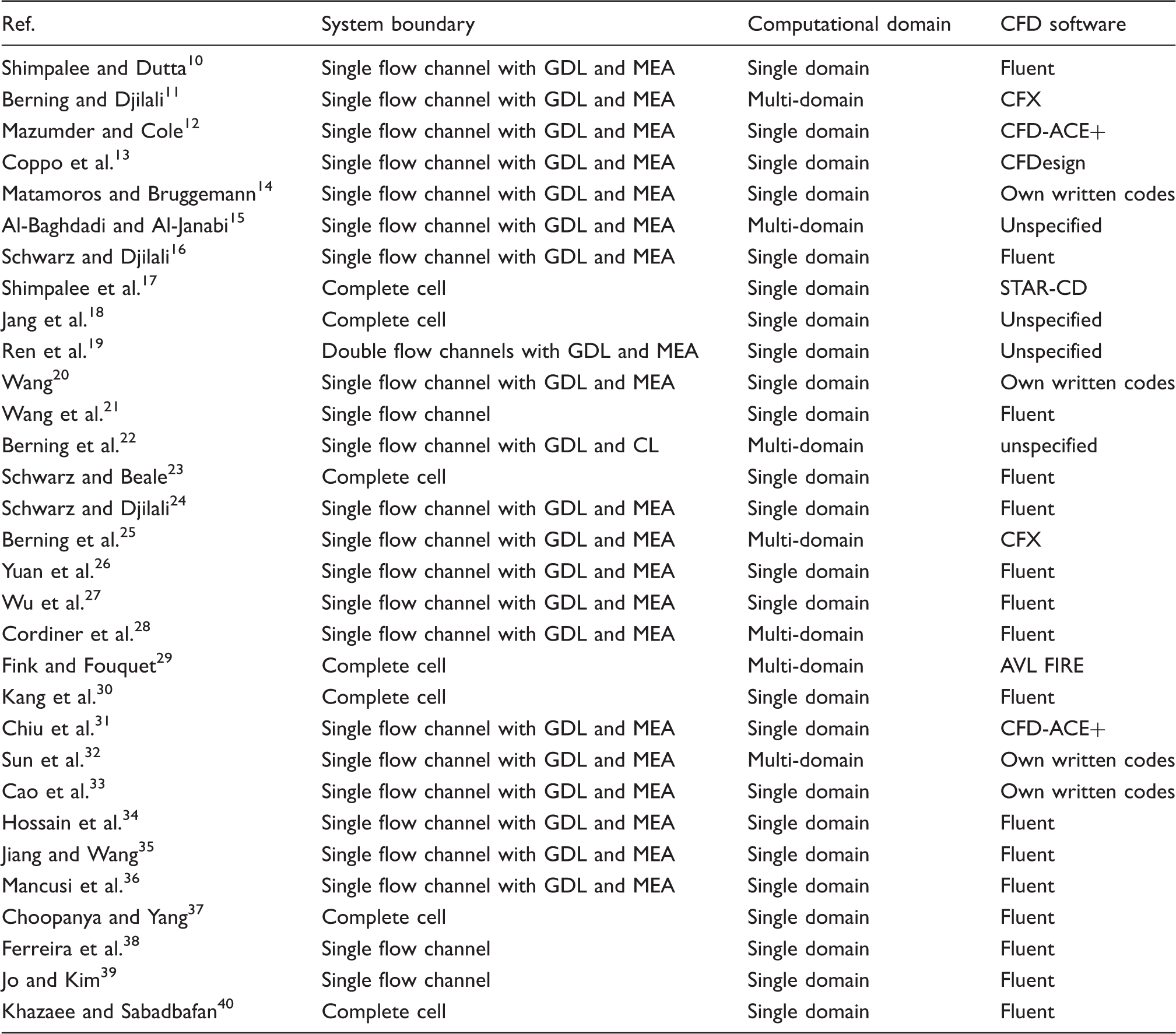
CFD: computational fluid dynamics; GDL: gas diffusion layer; MEA: membrane electrode assembly.
System boundary
In PEM fuel cell modelling, defining a manageable system boundary in order to reduce computational efforts without compromising accuracy is often necessary.
From Table 4, it is very apparent that the vast majority of the models analysed take advantage of the symmetric layout of the fuel cell geometry to only model a single GFC on both anode and cathode sides with the corresponding GDLs and CLs and the membrane as illustrated in Figure 4. This reduces the computational efforts considerably. A full 3D description of a complete cell or a fuel cell stack would require very large computing resources and overly long simulation time. Thus, a complete cell is only computed in five cases (in the models for geometry or operating condition effects mainly) and the simulation of a complete fuel cell stack is not performed.
A single straight channel with corresponding GDL and MEA. GDL: gas diffusion layer; MEA: membrane electrode assembly.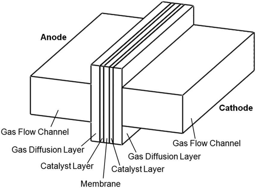
Computational domain
In terms of modelling domain (computational domain), two distinct approaches are used in the reviewed papers for computing the numerical solutions of PEM fuel cell mathematical models according to the different regions within the cell. These are single-domain and multi-domain approaches, with a greater number of the models reviewed adopting the single-domain approach (see Table 4).
In the single-domain approach, the generic conservation law equations are used for the entire modelling domain and only the source terms vary according to each region or component, whereas in the multi-domain approach different forms of the same equations are solved in each region or component within the cell, and boundary or initial conditions may be required on internal interfaces.
The advantage to the single-domain approach is that it does not require the specification of interface conditions between the individual fuel cell components and aid in parallel computing. It may however involve a careful numerical manipulation of the equations to retain a model that is physically realistic since all of the equations are solved at once over the entire model which can also be wasteful in terms of memory and speed.
The multi-domain approach can efficiently deal with decoupled components. It is however inefficient when coupling dominates and it does not readily facilitate parallelization.
Solvers
As explained in ‘CFD’ section, for a CFD solver to solve a non-linear differential model, this must first be converted into a system of linear algebraic equations. In most CFD software, this conversion is performed by means of the finite volume method (FVM), which discretizes both the computational domain and the conservation equations using highly sophisticated algorithms.
For the coupling of velocity and pressure, the majority of the available CFD codes use the semi-implicit method for pressure-linked equations algorithm although the pressure-implicit split-operator algorithm is also used.
Based on the literature model overview, one can say that Fluent is well suited for 3D PEM fuel cell modelling. More details on the most frequently used CFD codes for PEM fuel cell simulation is provided in ‘CFD codes for PEM fuel cell modelling’ section.
CFD codes for PEM fuel cell modelling
There are several CFD codes that can be used for PEM fuel cell model simulation ranging from commercial software through open source free codes to own written programs.
Although most of these software use similar techniques for the discretization of both the computational domain and the partial differential equations (e.g. FVM) and have similar capabilities to deal with the multidimensional effects of the phenomena taking place in the fuel cell, they occasionally differ in their approach to modelling multiphase flow and the phase change processes.
This section gives a brief overview of the most commonly used CFD software for the numerical modelling and simulation of PEM fuel cells.
Commercial codes
AVL FIRE™
AVL FIRE is a multi-purpose thermo-fluid CFD software package that is capable of simulating fluid dynamics problems involving complex geometries and the interplay of advanced physics and chemistry. 57
The multiphase flow modules consist of Eulerian and Lagrangian multiphase modules. The Eulerian multiphase module uses the multi-fluid modelling approach of multiphase flow and thus allows the calculation of the volume fraction distribution for each phase in addition to all other flow variable. The Lagrangian multiphase module accounts for droplet break-up, turbulence dispersion, collision and coalescence, distortion and drag, evaporation as well as droplet/wall interaction. It thus allows a detailed study of the movements of the droplet. 57
CFD-ACE+
CFD-ACE+ is an advanced CFD and multi-physics software that enables coupled simulations of fluid, thermal, chemical, etc. phenomena. It is specifically designed for parallel computing on high performance workstations and clusters but it also works on normal computer systems. 58
The software provides built-in models for the modelling of electrochemistry and flow through porous media and small channels. The PEM fuel cell module accounts for the fundamental physics of PEM fuel cell. It includes a model for water transport through the membrane, a model for transport of liquid water saturation through the porous media, and the liquid saturation model for two-phase flow in the channels. 58
CFX
ANSYS CFX is a general purpose fluid dynamics program that offers an abundant choice of physical models, capturing any type of phenomena related to fluid flow. Its highly parallelized solver supports the simulation of flow in porous media, multiphase flow, phase change, and so forth. 59
Two distinct multiphase flow models are provided, Eulerian–Eulerian multiphase model and a Lagrangian particle tracking multiphase model. The Eulerian–Eulerian multiphase model allows the modelling of multiphase flow using either the multiphase mixture or the multi-fluid modelling approaches. The Lagrangian particle tracking multiphase model models the total flow of the particle phase by tracking a small number of particles through the continuum fluid. The particles could be solid particles, drops, or bubbles. 60
COMSOL Multiphysics®
COMSOL Multiphysics is a very versatile software platform for various coupled phenomena. 61
A battery and fuel cell module that can be used to model the underlying electrochemical phenomena in the electrodes and electrolytes of batteries and fuel cells is provided. The CFD module allows the modelling of multiphase flows as well as flow in porous media. Multiphase flow is modelled using the bubbly flow, multiphase mixture, or Eulerian–Eulerian multiphase models. Phase changes are described using built-in step functions. 61
Fluent
ANSYS Fluent is a general purpose fluid analysis software package with broad physical modelling capabilities for modelling flow, turbulence, heat transfer, and reactions for industrial applications. 62
It provides a fuel cell module that can be used for the modelling of electrochemistry, current and mass transport, heat source, liquid water formation, and transport in PEM fuel cells. 63
Two distinct approaches are used for the numerical calculation of multiphase flows: the Eulerian–Lagrangian approach and the Eulerian–Eulerian approach. In the Eulerian–Lagrangian approach the fluid phase is treated as a continuum by solving the Navier–Stokes equations, while the dispersed phase is solved by tracking a large number of particles, bubbles, or droplets through the calculated flow field. In the Eulerian–Eulerian approach, the different phases are treated mathematically as inter-penetrating continua. Three different Eulerian–Eulerian multiphase models are available in Fluent: VOF model, the mixture model, and the Eulerian model. 64
STAR-CD®
CD-adapco STAR-CD and STAR-CCM+ are well-established software platforms for industrial CFD simulation that are capable of solving complex multidimensional and multi-physics models.
STAR-CD has been used with a specialized PEM fuel cell module (es-pemfc) to gain a better understanding of water management as well as electrochemistry in PEM fuel cell, leading to optimized cell performance. 65
STAR-CCM+ can perform comprehensive simulations involving electrochemistry allowing fuel cell modelling. Multiphase flow modelling is completed using Eulerian multiphase model, with other models within the Eulerian framework, such as the Eulerian multiphase mixture model, VOF, fluid film, and the dispersed multiphase model. 66
Free codes
OpenFOAM®
OpenFOAM is an open source CFD code that can solve anything from complex fluid flows involving chemical reactions, turbulence, and heat transfer, to solid dynamics and electromagnetics. 67
The object-oriented design of the software which is written in C++ allows the implementation of own models and numerical algorithms. Thus, the user has complete freedom to customize and extend any existing functionality. 67
A wide range of solvers is provided for the simulation of flow in porous media and multiphase flows. The approaches available for the modelling of multiphase flows range from a system of two fluid phases model with one phase dispersed, through VOF phase fraction-based interface capturing approach, to multiphase mixture and multi-fluid models. 67
Other codes
Besides the conventional CFD codes outlined above, there exist other CFD codes which are also capable of performing the same numerical modelling and simulation of PEM fuel cells, and often with equal results. These are usually highly specialized own written programs developed by individual academic or industrial research groups. Multiphase flow is modelled using either the multiphase mixture or the multi-fluid modelling approaches mainly.
Summary and outlook
A comprehensive review of the open literature 3D multiphase CFD models for PEM fuel cell was conducted. This revealed the large volume of published work dealing with the modelling and simulation of transport phenomena in PEM fuel cells, as well as thermal management and the influence of geometry or operating conditions on the cell performance.
It is difficult to directly compare the published models because of the modelling of multiphase flow, phase change, and other modelling assumptions, as well as model validation methods used by the authors. Nevertheless, it appears that 1D and 2D models are only suitable when focusing on particular phenomena, whereas 3D models allow multi-physics simulations of a single component, a complete cell, or even a fuel cell stack and they can be used for design purposes.
Thus, the 3D PEM fuel cell models presented in a selection of journal papers were thoroughly analysed. This revealed that comprehensive 3D multiphase flow CFD models that elucidate the complex couplings of electrochemical kinetics and multiphase transport are still greatly in need though significant advances have been made in PEM fuel cell modelling.
Indeed, truly functional and predictive capabilities remain a challenge due to deficiencies in models for two-phase transport in the GFCs and the porous media. A further limitation of many of the existing comprehensive 3D models is that they do not consider the detailed composition and structure of the CLs, despite the important role of the CLs in determining the cell performance.
Therefore, more research is required to develop models that include the detailed composition and structure of the CLs. Such comprehensive models should also consider the effects of the movement of water droplet in the GFCs, the existence of phase change in both the anode and cathode sides of the fuel cell, as well as dissolved water transport and related phase change mechanisms. These matters have thus far received little attention.
As for the CFD codes used for PEM fuel cell modelling and simulation, it has been noted that the market is largely dominated by a few major brands, such as Fluent, CFD-ACE+, CFX, STAR-CD, COMSOL, AVL FIRE, and OpenFOAM. Although these software packages differ in appearance and capabilities, fundamentally they are all the numerical solvers of partial differential equations with attached multi-physics models and in some cases a specialized fuel cell module.
Finally, in view of all that has been mentioned so far, one may suppose that optimizing PEM fuel cell designs to provide better thermal and water managements, while reducing the costs associated with the testing and operation of PEM fuel cell remains a key technological challenge for this type of fuel cell. Thus, it is likely that in the future, with further advances in numerical procedures and computational techniques, CFD modelling and simulation will continue to play an important role in tackling this technological challenge for the PEM fuel cell technology.
Footnotes
Declaration of Conflicting Interests
The author(s) declared no potential conflicts of interest with respect to the research, authorship, and/or publication of this article.
Funding
The author(s) disclosed receipt of the following financial support for the research, authorship, and/or publication of this article: The authors acknowledge the financial support from the International Doctoral Innovation Centre, Ningbo Education Bureau, Ningbo Science and Technology Bureau, China’s MoST, and the University of Nottingham. This work was partially supported by Ningbo Natural Science Foundation Program (project code 2013A610107).