
Abstract
In this paper, the effect of near gravity material at desired separation density during the coal washing is studied. It is believed that the Dense Medium Separation of coal particles in the presence of high percentage of near gravity material, results in a significant misplacement of coal particles to wrong products. However the performance of dense medium cyclone does not merely depend on the total amount of near gravity materials but also on their distribution as well as on their quality. This paper deals with numerical simulation of magnetite medium segregation and coal partitioning handled in a 350 mm dense medium cyclone.
Volume of Fluid coupled with Reynolds Stress Model is used to resolve the two-phase air-core and turbulence. Algebraic Slip mixture multiphase model with the granular options are considered to predict magnetite medium segregation. Medium segregation results are validated against Gamma Ray Tomography measurements. Further, Discrete Phase Model is used to track the coal particles. Residence Time Distribution of different size and density coal particles are also estimated using Discrete Phase Model. Additionally, Algebraic Slip mixture model is also utilised to simulate magnetite and coal particle segregation at different near gravity material proportions. Discrepancies in the coal particle behaviour at different near gravity material content are explained using locus of zero vertical velocities, mixture density, coal volume fractions.
Keywords
Introduction
Dense medium cyclones (DMC) are widely used operating devices to separate clean coal from the mining coal with high throughputs and sharp separations. The usual size range involves 0.5–50 mm. DMC separates the coal particles by using a dense medium (suspension of superfine/ultrafine magnetite and water). The specific gravity (SG) of the suspension is adjusted to be between clean coal and associated mineral matter densities for coal preparation plants. Most of the Indian coals have difficult washing characteristics due to high ash levels and high portion of Near-Gravity Material (NGM). NGM is defined as the portion lying within ±0.1 Relative Density (RD) of chosen cut density. The presence of NGM and their course of movement influence the separation gradient which directs the coal particles to wrong product. As a result, DMC’s performance decreases due to the misplacement caused by NGM content of the given coal.
In DMC, the feed material, i.e. mixture of raw coal combined with magnetite medium enters tangentially near the top of the cylindrical section, thus forming strong vortex flow. The centrifugal force associated with vortex flow causes the high dense ash particles to move along the wall and discharge as underflow. The drag force causes the low density clean coal to move towards longitudinal axis and discharge as overflow. The existence of magnetite medium, coal of different sizes, densities along with turbulence makes the flow in a DMC very complex.
Literature review
Sarkar et al. 1 studied the effect of NGM in a 150 mm DMC at a feed RD of 1.5. It was observed that, an increase in the NGM content has an adverse effect on the DMC performance. Based on the industrial experience, Sripriya et al. 2 stated that the rheology and flow stability of dense medium suspension have a great influence on the performance of DMC treating NGM coal. Experiments were conducted with controlled addition of viscosity modifiers and observed an increase in the sharpness of separation in a 610 mm DMC. Further, Ecart Probable Moyen (EPM) values of DMC were compared with Versatile Separator (VS). In all the experimental conditions, a lower EPM was associated with VS compared to DMC. de Korte 3 proposed a new definition for NGM, i.e. material lying in the density range of ±2× EPM from the cut point density and observed that an increase in NGM content increases the misplacement of the particles particularly at smaller sizes of the particle. Magwai and Classen 4 reported that replacement of 710 mm with 800 mm DMC in the Dense Medium Separation (DMS) plant at Leeupwpan coal mine improves the efficiency of DMC treating high NGM coal. Increased efficiency was also observed with larger spigot at constant feed conditions and vortex finder diameter. Larger spigot provides more flow area, thus, reduces the risk of overloading at the spigot and decreases the risk of misplacement. Meyers et al. 5 reported lower EPM values when the NGM experiments were conducted at low Medium to Coal (M:C) ratios. Napier-Munn 6 performed the experiments with different density tracers and observed that, coal density near/equal to the separation density exhibits maximum residence time compared to the higher/lower coal densities.
In the recent, Computational Fluid Dynamic (CFD) models based on fundamentals of fluid flow were successfully utilised to understand the flow dynamics inside the DMC.7–13 Initially, the CFD modelling of DMC was started with 2D grids and axis symmetric assumptions. 14 However, it was proved that 3D geometry was necessary for accurate flow field predictions thereby performance. In the earlier studies, turbulence was modelled with Prandtl mixed length, κ–ɛ and Re-Normalisation Group (RNG) κ–ɛ models and observed deviations in comparison with experimental measurements. Reynolds Stress Model (RSM) solving additional transport equations for the extra stresses able to provide appropriate results in various designs of DMC. Albeit Large Eddy Simulation (LES) turbulence model needs fine grid and high computation time, it was able to provide more accurate predictions compared to RSM model because of its ability to solve large scale eddies and model the small scale eddies.8,9
The flow in cyclones involves different phases like air, water, magnetite and coal of different sizes and densities. Therefore, there is a need of multiphase model for efficient modelling. There are number of multiphase models available in CFD for simulating such complex flow behaviour. These include the full Eulerian multiphase approach, the simplified Eulerian approaches such as Volume of Fluid (VOF) 15 and Algebraic Slip mixture (ASM) 16 model and the Lagrangian approach. 17 In the early 2000s, the two-phase flow (water–air) in the DMC was modelled using VOF. Further, coal particles were tracked using Lagrangian approach.17 Brennan 18 successfully utilised ASM model for medium segregation prediction with average particle size and density. Though the results obtained showed satisfactory segregation levels but it was not on par with experimental Gamma Ray Tomography (GRT) data. The ASM model was later modified by Narasimha et al.8–10,19 including shear lift forces, viscosity correction generated improved medium segregation results compared to GRT data. This modified ASM model was successfully implemented in the research work to predict flow properties in the hydrocyclones and DMCs.13,20,21
In most of the studies,10,12,22 coal particles were tracked using Discrete Phase Model (DPM). They were able to predict pivot phenomena (partition curves of different density particles pass through a single point) using DPM model. It was observed a small deviation in separation density due to the assumption of dilute coal concentration. Surging may arise due to instability of medium flow which may result from improper DMC design or operation. The absence of particle–particle interactions in DPM model can be resolved using Discrete Element Method (DEM). A one-way coupling method CFD-DEM was proposed by Chu et al. 23 with an assumption of ignoring particle effect on medium flow. Later two-way coupling CFD-DEM model was proposed by Wang et al., 21 the concept of introducing parcel particles. As parcel particles are not real and it is difficult to understand the fundamentals clearly, so a detailed and realistic work is needed to simulate the coal particles. Even the CFD-DEM model is computationally very demanding, the computational time is more to get the results and this effect made the use of DEM limits to study coarse particle but not on fine particles. Kuang et al. 24 used Two-fluid Model (TFM) to overcome this deficiency and to study the performance. A comparison study is made between three models CFD-DEM, CFD-DPM and TFM on particle behaviour and validated with experimental data. 25 It was observed that the efficiency is decreasing w.r.t particle size. It was noticed that TFM was showing consistent results with and with out particle–particle interaction. Despite numerous numerical studies made in the past, no attempt has been made so far to address the NGM particle behaviour in DMCs.
Most of the past works7–13 mainly concentrated on medium segregation with limited validation GRT data. 26 The coal partition is primarily modelled using DPM model. Although CFD-DEM model studies are available; DEM model is computationally expensive and closure for particle–particle interactions is still under evaluation process. Here the coal partitioning is addressed individually. In this paper, numerical simulation of magnetite medium segregation and coal partitioning has been studied in a 350 mm DSM cyclone for various NGM fractions. Much focus was made on coal particle dynamics using DPM and ASM model. In particular NGM particle trajectories, RTD, local segregation coupled with magnetite medium are observed and studied. The effect of NGM fraction on overall cyclone performance and product density differential is analysed.
Modelling methodology
Turbulence modelling
The CFD approach used here is same that used by Brennan et al.
27
and Narasimha.
28
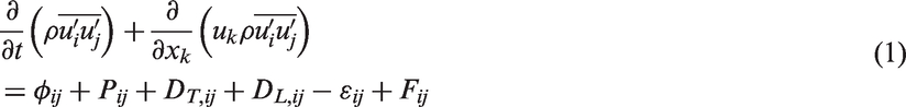
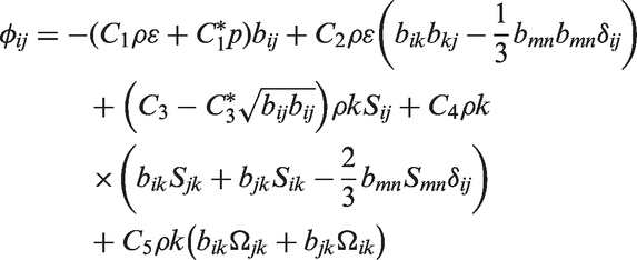
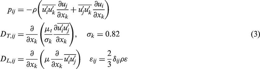
The flow turbulence is modelled using RSM to resolve the turbulent mixing. Unsteady transport equations given below are solved for individual Reynolds stresses
Here
Multiphase modelling – Modified ASM model with lift forces
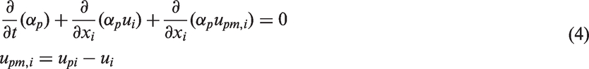
In the ASM,
16
mixture velocity is calculated by a single momentum equation; volume fraction of each phase is obtained by solving individual continuity equation. Continuous Fluid phase is assumed as primary (represented by c); particles are assumed as dispersed phase (represented by p).
Drift velocity of the mixture
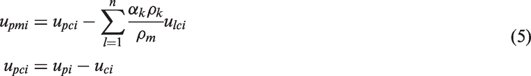
The general slip velocity
The last acceleration term in the bracket is due to lift force. This equation is implemented in Fluent by a custom slip velocity user defined function. Lift coefficient is modified as suggested by Mei
30
to apply it for high Reynolds number. The modelling f of

The slip velocity
Slurry rheology
As a base model, calculations are performed with basic granular viscosity (GV) formulation incorporated in Fluent which has been used by Ding and Gidaspow 33 and Gidaspow et al. 34 Granular shear viscosity arises from particle momentum exchange due to translation and collision is accounted by enabling the granular solid option. Details of GV formulation incorporated in Fluent manual. 35
The default model is a simple calculation of weighted means of viscosity. To describe the mixture viscosity more realistically it is calculated using Ishii and Mishima 36 viscosity model.
The mixture viscosity is given by the following equation

DPM model
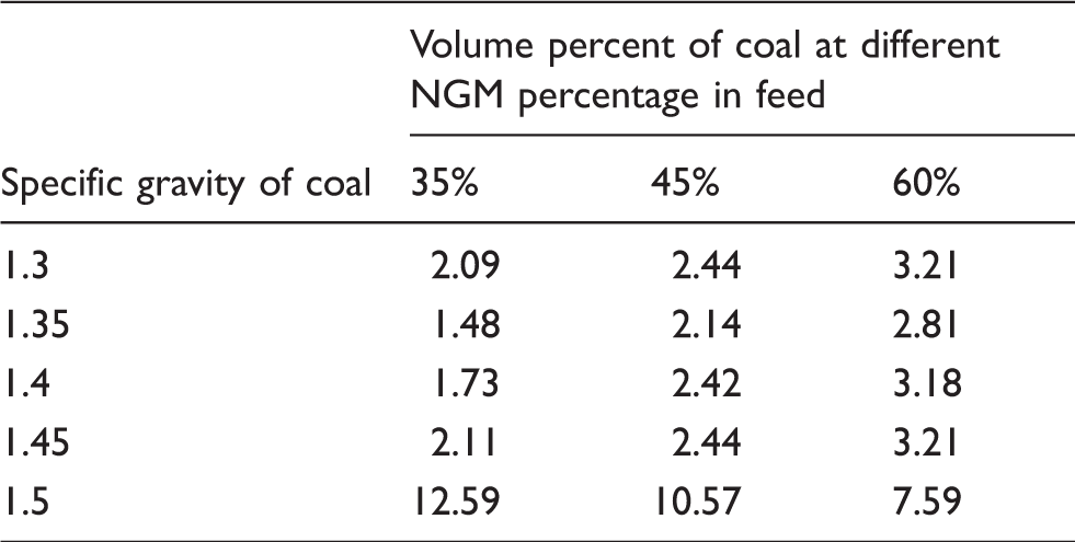
The motion of coal particles is defined by the so-called Lagrangian multiphase flow model. The pressure and drag forces on particles are calculated in a Lagrangian frame. The velocity distribution of particles can be evaluated by the force balances on the particle. The governing equation is as follows:


Numerical modelling
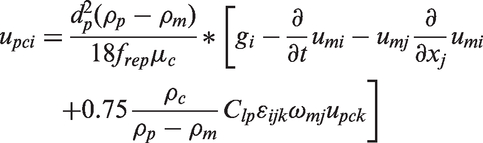
Properties of the fluids.
In the primary approach, magnetite medium segregation is predicted using ASM. Further, using the DPM model coal particles (∼2000) are injected continuously as discrete phase. In DPM, coal particles of different sizes in the range of 0.5–8 mm with density ranging from 1200 to 2000 kg/m–3 are considered. The maximum number of steps used is 5 × 10⁷ with sphericity of 0.8 and Saffman lift force 37 physical model. The turbulent dispersion is modelled using discrete random walk (DRW) model with random eddy lifetime. After collecting the number of coal particles reported to overflow and underflow, the partition number is calculated and the performance indices are evaluated.
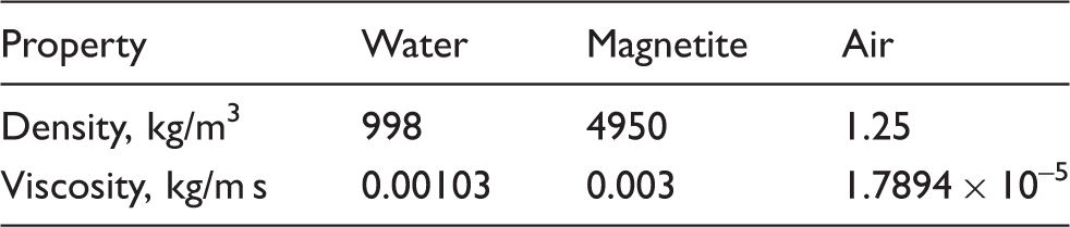
Volume fraction of coal used in simulation.
NGM: Near-Gravity Material.
Results and discussions
The flow field predictions and mesh independence check for 350 mm DMC is similar to the work reported by Vakamalla and Mangadoddy.
19
Three grid sizes, 100 k, 200 k and 400 k are chosen for the mesh independence. VOF coupled with RSM turbulence model is utilised for initial two-phase air-core and velocity predictions. The comparative study of velocity predictions is performed w.r.t. to selected grid sizes and an optimum grid size of 200 k nodes is chosen and shown in Figure 1(a) to (d).
(a) Detailed geometry of 350 mm DMC with (b) numerical grid of 200 k, (c) inlet and (d) o-grid.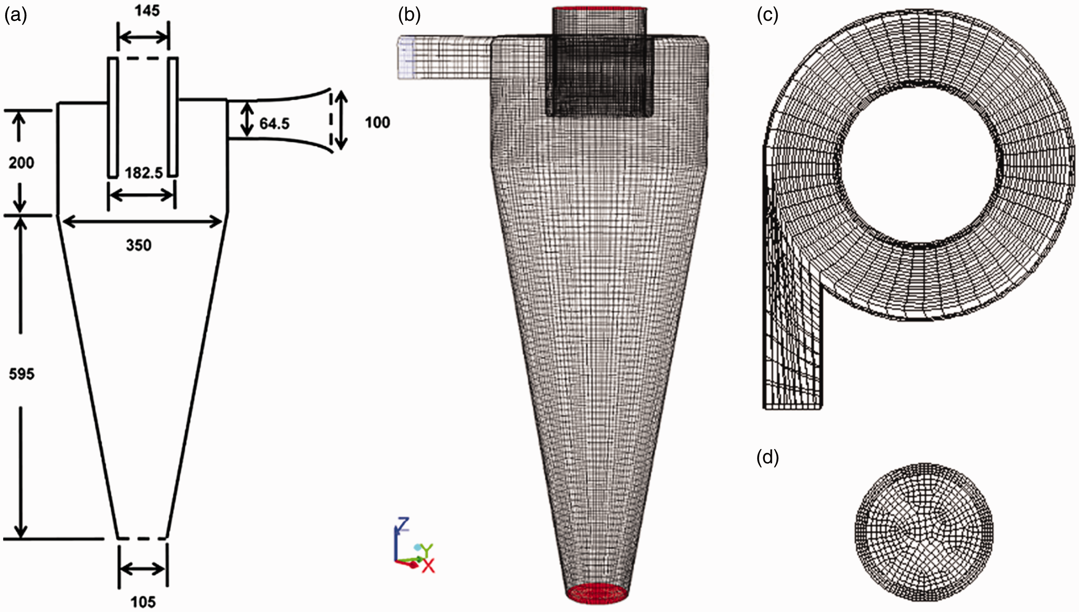
Air-core predictions
The air-core formation and magnetite segregation are studied with modified multiphase ASM model with lift forces and GV model. The predicted air-core radius with ASM model coupled with RSM turbulence is shown in Figure 2 and compared to the experimental GRT data.
26
From Figure 2, it is observed that the predicted radius is close to experimental values except a slight variation in the cylindrical section.
CFD predicted air-core radius compared against experimental air-core radius for the 350 mm DMC at a feed RD 1.3.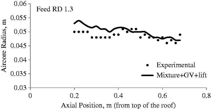
Magnetite segregation with modified ASM model followed by coal partitioning with DPM model
Magnetite segregation by ASM model: To analyse magnetite segregation in a 350 mm DMC, simulations are carried out with GV based ASM model with lift forces for feed RD of 1.3. This approach is similar to the work presented by Brennan.
18
Figure 3 displays the qualitative comparison of CFD predicted mean mixture density with GRT data.
26
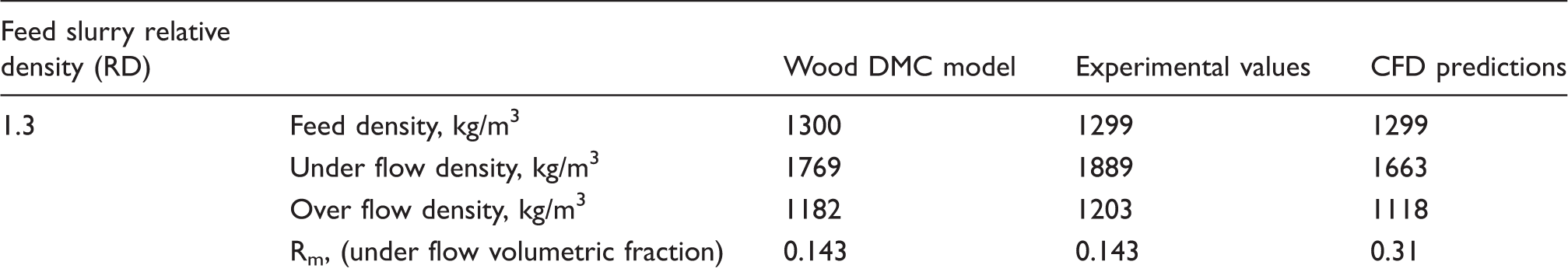
From Figure 3, it is observed that the medium densities are slightly over predicted near the wall. The over prediction of densities may be due to the sudden increase in the volume fraction levels near the cyclone wall. The computed values of overflow and underflow densities and underflow volume fractions (Rm) are tabulated in Table 3.
Mean mixture density contours: (a) GRT data of Subramanian
26
and (b) CFD prediction with RSM model for feed RD of 1.3. Comparison of predicted flow rates with experimental and standard models. RD: Relative Density; DMC: dense medium cyclones; CFD: Computational Fluid Dynamics.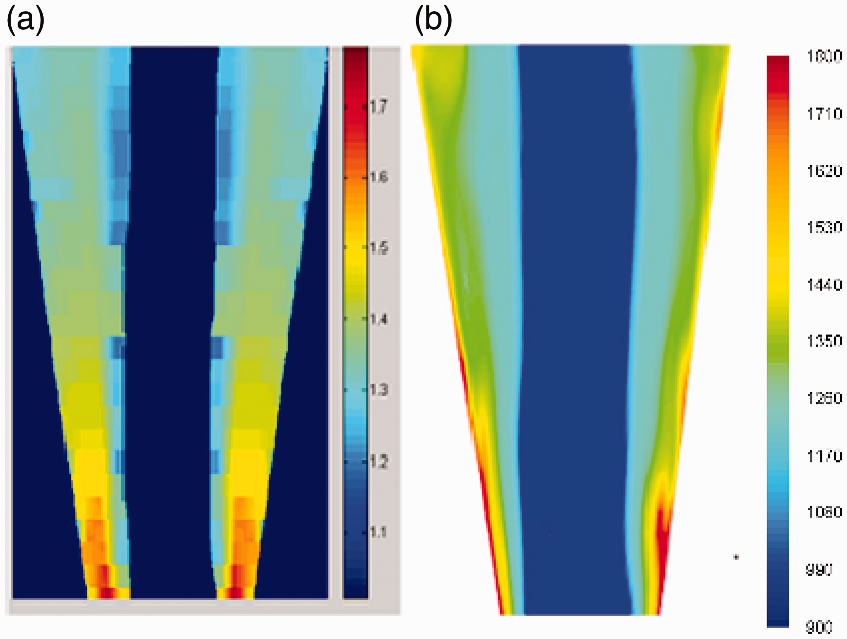
Coal partitioning using DPM model: In DPM model, the coal particles are superimposed as dispersed phase on steady state segregated medium assuming it as continuous phase. Figure 4 shows the partition curve for dispersed coal particles collected at underflow w.r.t. density for different particle sizes at 1.3 feed RD. It is observed that the cyclone is more efficient for the large size particles than for the small size particles. It is also shown that the particle with high density far away from separation density is going to underflow and less dense particles overflow with high efficiency. But the particle having the density close to the separation density usually called as NGM particle shows less efficiency to pass through their respective exits. An attempt is made to understand particle behaviour whose densities are close to the cut point densities by their residence time inside the cyclone. Figure 5 shows the Residence Time Distribution (RTD) curve w.r.t. density at each uniform size considered for the study.
Partition curve for the coal particles of feed RD 1.3. RTD versus coal particle density for feed of RD 1.3.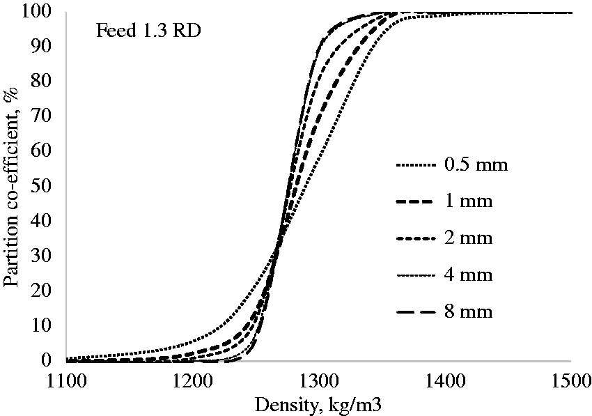
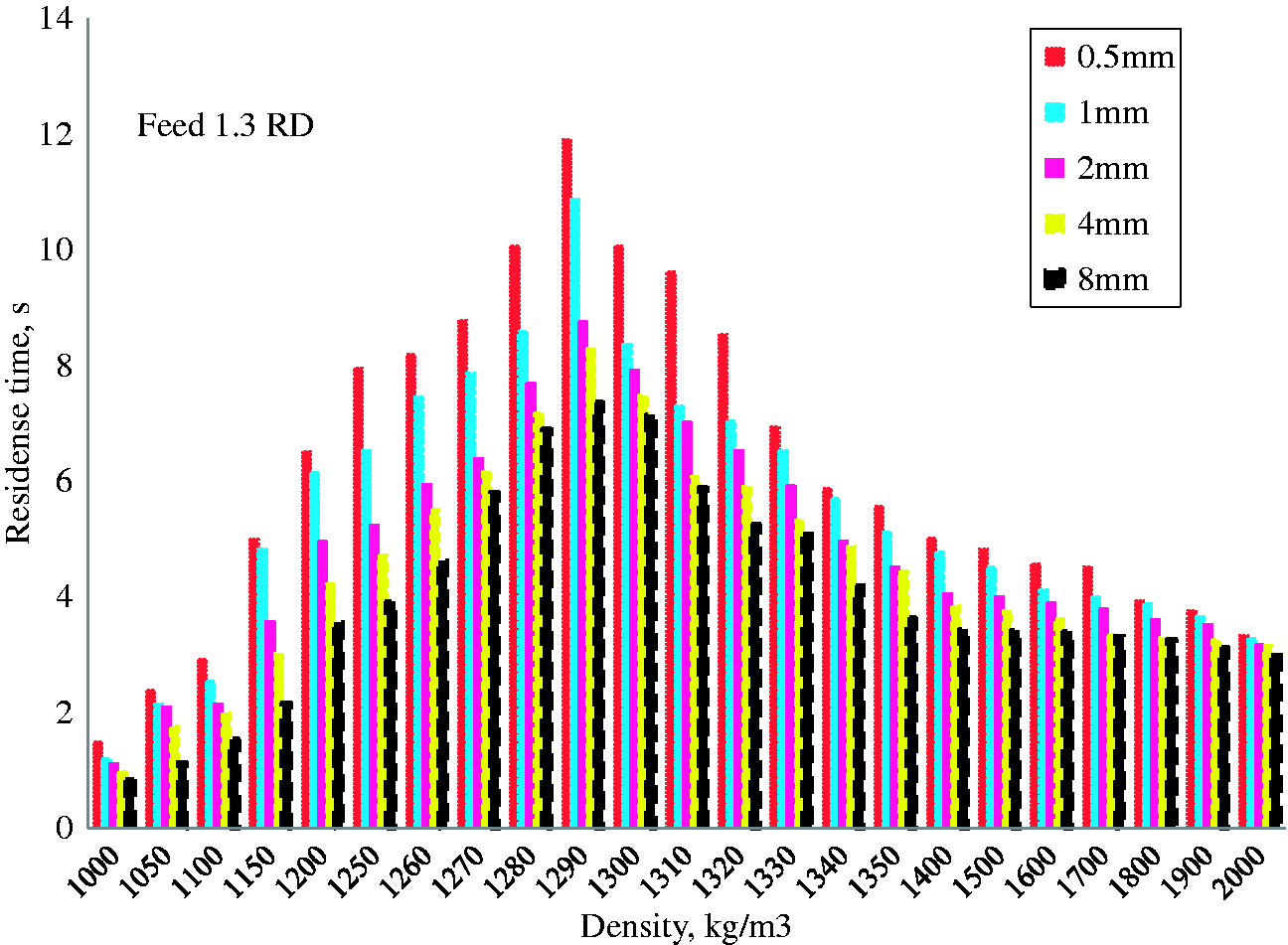
It is observed from the RTD curve that the very low and very high density particles show less residence time compared to the particles whose density near the separation density is 1300 kg/m3 for all size particles. For the feed RD 1.3, the coal particles of density ranging from 1.2 to 1.4 are defined as NGM, showing long residence time. It is also observed that the small size particles are having longer residence times compared to large size particles at the same density as shown in Figure 6.
Maximum values of residence time w.r.t. different coal size particles at RDs of 1.3.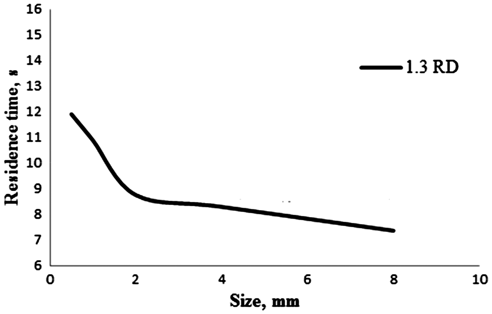
Figure 7(a) and (b) represents single coal particle trajectories of sizes namely 0.5, 2 and 8 mm at 1290 kg/m3 (near to separation density) and at 1600 kg/m3 (far from separation density). It is observed in Figure 7(a) that the small size particles are taking long residence time compared to coarse size particle particularly near to separation density. The long residence time of the NGM particles will lead to misplacement to wrong products. But the particles of density away from separation density irrespective of sizes spending very less time are shown in Figure 7(b).
(a). Particle trajectories of 0.5 mm, 2 mm and 8 mm at 1290 kg/m3 near to cut density. (b). Particle trajectories of 0.5 mm, 2 mm and 8 mm at 1600 kg/m3 away from cut density.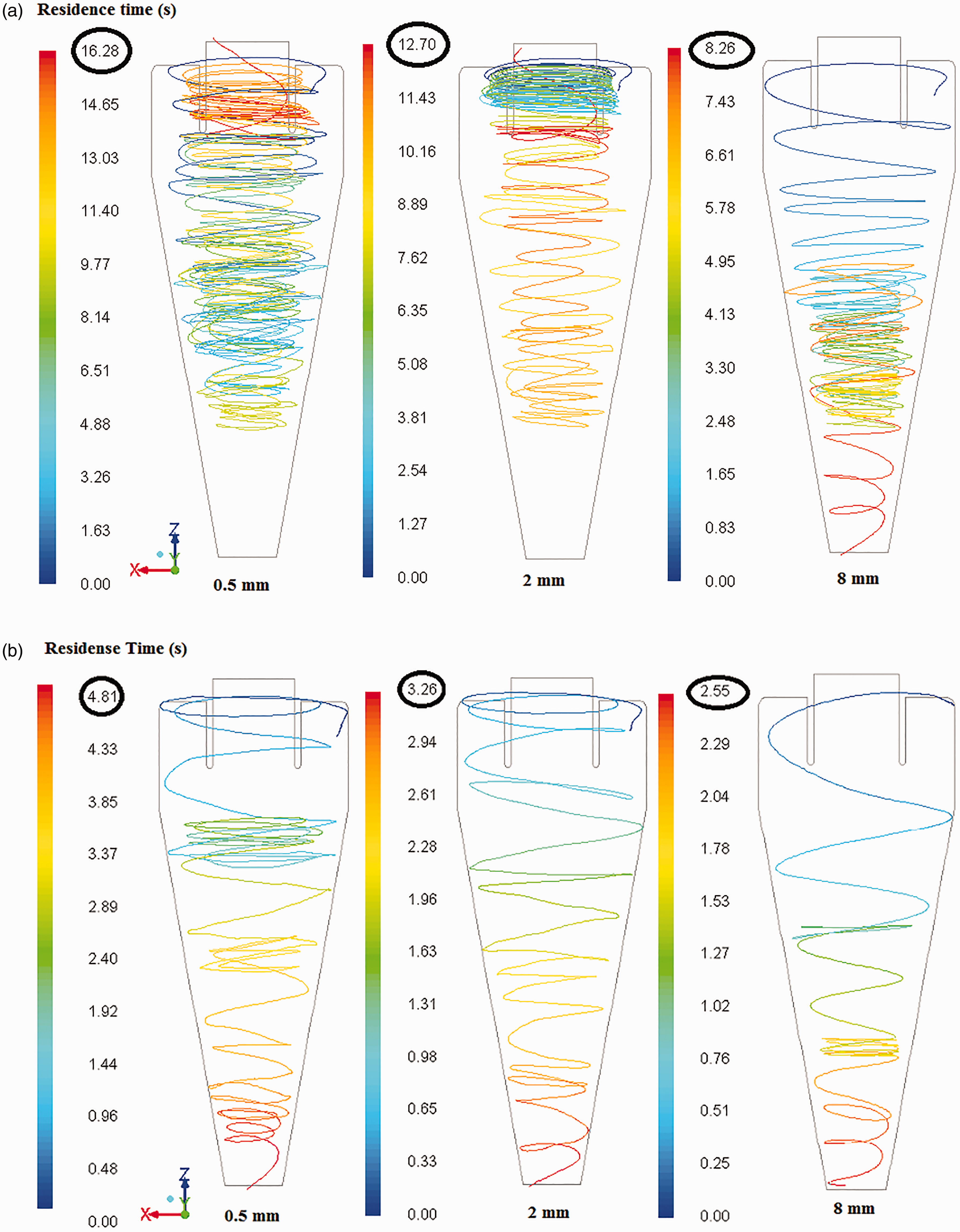
Analysis of multiphase data using modified ASM model with a viscosity correction at different NGM proportions in the feed coal
Modified ASM along with Ishii and Mishima
36
viscosity correction is used for simulating multiple phases with varying NGM proportions in the feed coal. The multiple phases considered are size distribution of magnetite, coal particles of different densities with uniform size, air and water. Predicted distribution of magnetite and coal is presented at different percentages of NGM of coal size 0.5 mm. Figure 8 displays the predicted mean feed mixture density contours at different NGM content. A small variation is observed at vortex finder region. A quantitative representative of same w.r.t. to radial direction is shown in Figure 9 at different axial positions of cyclone namely 0.27 m, 0.47 m and 0.61 m. It is observed that at axial position of 0.27 m, the density decreases with increasing NGM content near to the air core. This may be due to accumulation of more near gravity coal particles. Moving to the conical section, the density slightly increases compared to the cylindrical section. This may be due to the accumulation of high volume fractions of high density coal particles. This may result in increasing the residence time of coal particles and misplacement of particles, which can influence the separation efficiency.
Predicted mean-mixture density distributions at different NGM content for feed RD of 1.3. Predicted mean-mixture density profiles at different NGM content for feed RD 1.3.
Figure 10 shows the comparison between locus of zero vertical velocity (LZVV) profiles for only water, only medium and for overall medium and coal simulations at different radial positions. According to equilibrium orbit theory,
38
the particle position outside LZVV reports to underflow and inside LZVV reports to overflow. Shifting of LZVV towards wall is observed in coal plus magnetite simulations. The shifting may be due to the coal particle segregation inside the cyclone. With an increase in NGM content, this shift increases; reason may be due to the accumulation of high volumes of near gravity coal particle towards the air core.
Comparative LZVV profiles of only water, only medium and mixture of medium and coal cases.
Figure 11 represents the contours of coal volume distribution with increased NGM content. With 35% and 45% NGM content, the coal volume is more at air-core and cyclone wall near to the spigot. But with 60% NGM content, the coal volume is dispersed along the space between the air-core and cyclone wall near to the spigot.
Overall mean coal volume distribution contours for feed RD 1.3 at different NGM levels.
Figure 12 represents the contours at specific density 1350 kg/m3 w.r.t. increasing the NGM percent. Clearly it was showing that the accumulation of coal particles near the air core increases with NGM content which is consistent with mixture density data. This accumulation of the coal particles is the cause of the decrease in the mixture density. This results in increase in residence time followed by misplacement of the particles to wrong products.
Volume fraction contours of specific coal particles density 1350 kg/m3 with increasing NGM proportions.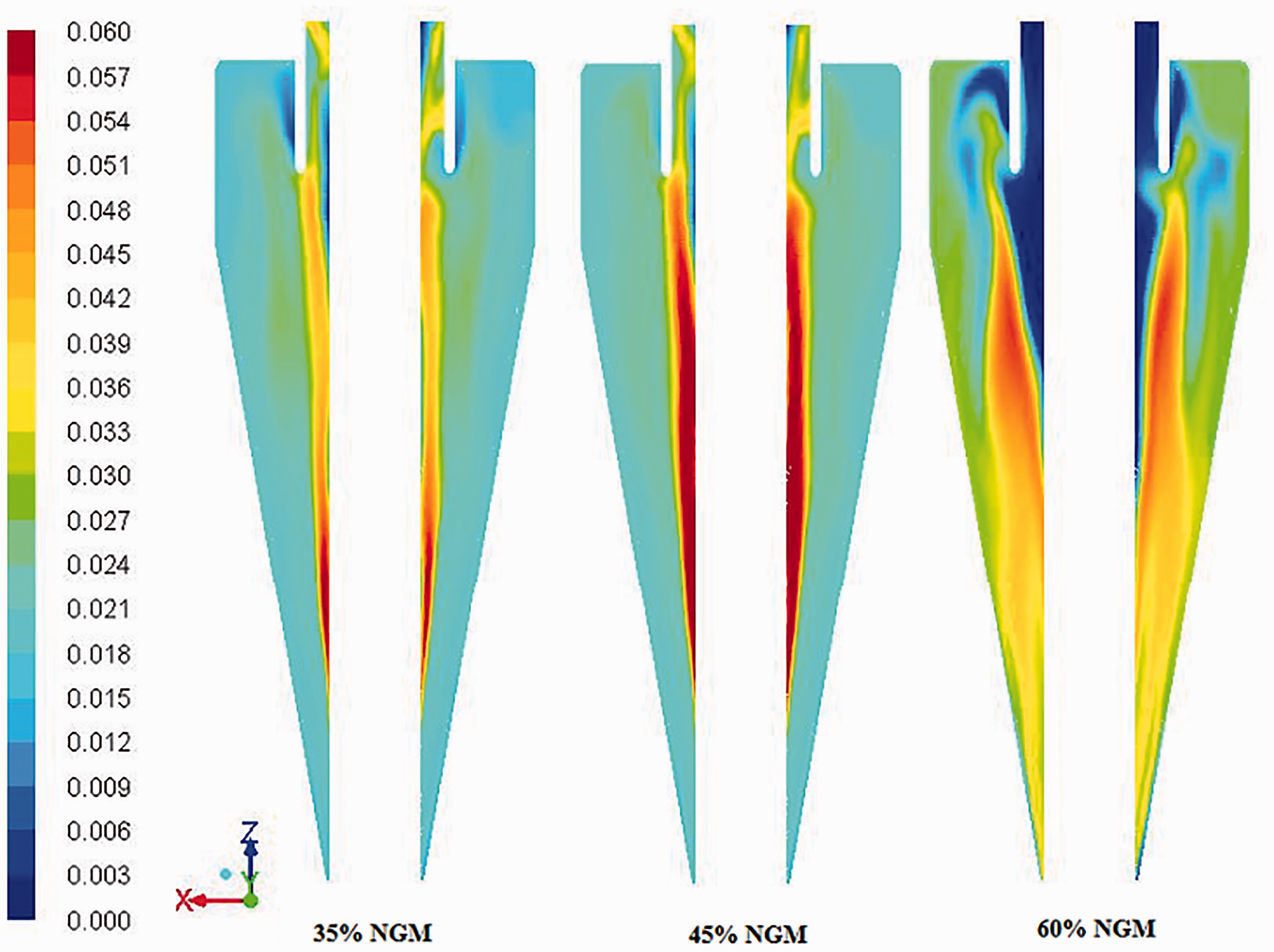
Figure 13 represents the mean position of maximum volume fraction of coal at a particular SG with increased NGM content. With 35% and 45% NGM content, coal concentration is high near to the air-core for SG 1.3 and 1.35 and for SG 1.4 and 1.45, the concentration is more near to the cyclone walls. With 65% NGM content, a distributed coal concentration is observed from air core to cyclone wall at all SG of coal. From Figures 11 and 13 with 35% and 45% NGM content, it is observed the accumulation of NGM coal is more at the air-core which affects the flow of other coal particles than NGM coal. This accumulation effect more for flow of coal particles than NGM coal leads to misplacement and also reduces the separation efficiency. Thus with high NGM coal content it may be difficult to separate clean coal at all relative densities.
Mean position of maximum volume fraction of different SG coal at various NGM fractions.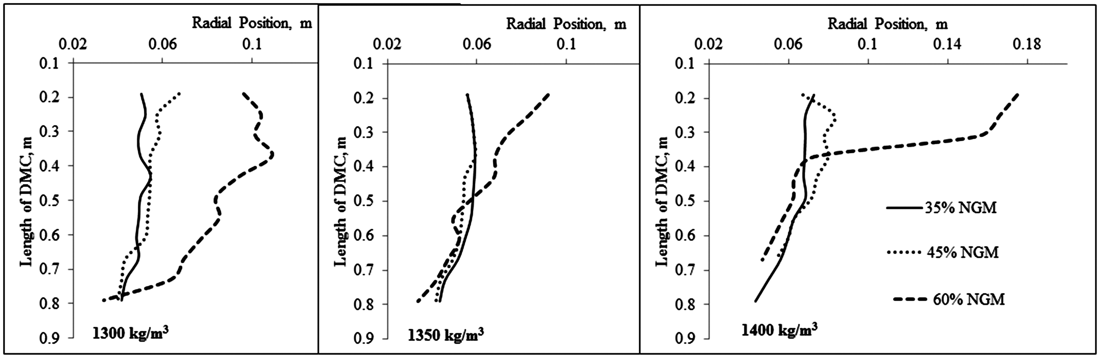
Conclusion
Magnetite medium segregation is simulated using modified ASM model coupled with RSM turbulence model successfully and the same validated against the GRT data.
26
DPM model is run superimposed on the converged medium simulations for the coal particle trajectories inside the DMC and an attempt is made to understand the RTD of different size and density coal particles. Coal particles having density near to separation-density exhibit increased residence time compared with other particles. As expected, the smaller size coal particles show higher residence time than the coarse coal particles. CFD simulations on the effect of NGM fraction are initiated using ASM model including for coal and magnetite. Coal particles with high NGM content show significant effect in misplacement of coal particles towards wrong products at all relative densities. The residence time of the particles increases because of its increased interaction with near dense particles.
Footnotes
Declaration of conflicting interests
The author(s) declared no potential conflicts of interest with respect to the research, authorship, and/or publication of this article.
Funding
The author(s) disclosed receipt of the following financial support for the research, authorship, and/or publication of this article: Authors would like to express their sincere thanks to NMDC Limited, India, for their generous financial support and encouragement to undertake these studies. Authors also want to extended their thanks to Confederation of Indian Industry (CII), Government of India for the Prime Minister fellowship.