
Abstract
The supercavitation technique provides a means of significantly increasing the velocity of an underwater vehicle. This technique involves essentially the creation of stable supercavity shape. The method of artificial ventilation is most effective for generating and dominating the supercavity. This paper focuses on the numerical simulation of flow field around three-dimensional body. The method is based on the multiphase computational fluid dynamics model combined with the turbulence model and the full cavity model. The fundamental similarity parameters of ventilated supercavity flows that include cavitation number, Froude number Fr, entrainment rate CQ, and drag coefficient Cx are all investigated numerically in the case of steady flow and gravity field. We discuss the following simulations results in three parts: (1) the variations of the cavitation number and the supercavity’s relative diameter with entrainment rate; (2) the drag coefficient versus the cavitation number; and (3) deformation of supercavity axis caused by gravitational effect for three different fixed three Froude numbers. In the full paper, we give the comparison results of the drag reduction ratio among numerical simulation and experiment conducted in hydrodynamic tunnel and towing tank, respectively. We summarize our discussion of gravitational effect on the axis deformation of supercavity as follows: in the case of smaller Froude number, the inclination of the cavity axis increases monotonously with increasing horizontal length and reaches its maximal value at the end of supercavity; this deformation can be almost completely negligible when the Froude number Fr is larger than 7.0. The comparisons with the experimental data in the hydrodynamic tunnel and the towing tank indicate that the present method is effective for predicting the flows around ventilated supercavity; that the numerical results is in good agreement with the experimental ones and that the maximal value of the drag reduction ratio can be expected to reach the value of 90% compared with that of the condition of non-cavitation.
Keywords
Introduction
Achieving ultrahigh speed is an important issue for underwater vehicles and has preoccupied scientists worldwide for decades. Even the fastest underwater vehicle was still restricted to travel at speed around 50 knots. The main reason is that the skin friction resistance underwater is much higher than that in the air. The speeds of about 50 knots represent an important barrier for high-speed vehicles. At this speed, cavitation typically starts to be a problem, for instance, on the foils and the propulsion system. Conventionally, cavitation means that the pressure somewhere on the upper side (suction side) of the foil becomes equal to the vapor pressure. This is only 0.012 times the atmospheric pressure at about 10℃. If a large part of the suction side of the foil is cavitating, the lift is clearly reduced relative to a non-cavitating foil at the same speed. 1
One promising technique to overcoming this speed limit is the use of the concept of supercavitation technique. This technique means that the suction side of the foil is not wetted. Partial cavitation may also cause damage to the foil structure in terms of implosion of bubbles. In addition, ventilation may occur, for instance, as a consequence of cavitation. Ventilation means that there is a connection or an air tunnel between the air and the foil surface. Occurrence of ventilation can also lead to significant drop in lifting capacity of a foil. Supercavitating foils and propellers are used to increase the speed barrier substantially beyond 50 knots. Such foil shapes have a sharp leading edge to initiate cavitation. The supercavitation provides a means of significantly increasing the velocity of an underwater vehicle. High-speed vehicle of supercavitation is a fascinating topic and becomes an important issue nowadays.
For some vehicles traveling through water, it is advantageous to cover the vehicle in a supercavity for the sake of reducing the drag acting on it. The underwater vehicle traveling enveloped inside a supercavity has only small regions at the nose (cavitator) and on the afterbody in contact with water. It provides a kind of means of significantly reducing the drag for a submerged body, thus enabling a dramatic increase of an ultrahigh speed (above 100 m/s). Now such a noticeable technology achieves breakthrough in its application only in one or two countries in the world. A supercavitation vehicle needs to be supplied with an artificial cavity through ventilation until it accelerates to the condition at which a natural supercavity occurs and sustains. By supplying the air/gas that is insoluble or non-dissolving in the operating liquid into the cavity, the ventilated supercavity can be maintained, even if the cavity pressure is much higher than the vapor pressure. The method of obtaining supercavitation by artificially blowing the gas into the rarefaction zone past a body with sharp edge was proposed firstly by Epshtein and Reichardt. 1 Such an artificially ventilated method has been employed frequently in hydrodynamic tunnel to investigate the mechanics, characteristics, and behavior of supercavitation, which is one of the complicated phenomena associated with underwater vehicles. It is possible to create and study supercavitation under significantly lower mainstream using the method. For high speed fully submerged underwater vehicles, e.g. projectiles and torpedoes, ventilated cavitation has been proposed to realize drag reduction by injecting gas in the wake region behind a cavitator, forming a continuous cavity covering the object surface. With the entire body being immersed in the cavity, friction drag may be significantly reduced by over 88%.2,3
The cavity shape is a matter of scientific interest, and it is also of great importance to the designer of underwater missile or rocket. The stability of a missile may depend on whether the cavity length is sufficient to envelop its fins or rudders, and its diameter may have great influence on the straightness of its trajectory. The cavity shape depends primarily on cavitation number and its size mainly on the drag force of the so-called cavitator. However, owing to some special difficulties in the experiment conducted at hydrodynamic tunnel, it is necessary to perform numerical simulation for compensating the deficiency of practice. The basic similarity parameters of ventilated supercavitation flows are cavitation number, Froude number, entrainment rate, drag coefficient, etc. They are all simulated numerically in the present paper.
Numerical model and methodology description
Numerical simulation of cavitating flows based on multiphase flows presents two challenges: (1) Modeling of several interdependent physical phenomena; and (2) Robust algorithm for handling inherently dramatic variations in fluid density due to very large ratios of liquid, vapor, and gas density, as well as complex geometries, often with moving parts. Kunz et al.4,5 and Singhal et al.6,7 had presented independently the cavitation model to meet such stiff requirements, with implementation of the commercial code, Fluent and CFD-ACE+.8–10 Based on mixture multiphase model, the CFD model, the standard viscous flow (Navier-Stokes), equations for variable fluid density and Shear Stress Transport turbulence model (e.g., SST model) are solved in this paper. Two additional transport equations are introduced to describe the fluid density which is a function of vapor mass fraction. The solver for these equations is the celebrated SIMPLE algorithm.11,12
Basic governing equations
The basic equations that include continuity, momentum conservation equations, and turbulence model are shown as follows:
Continuity equation

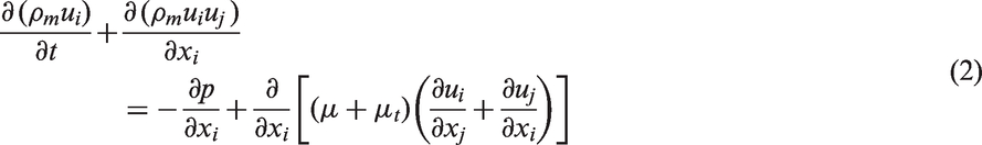
Momentum equation
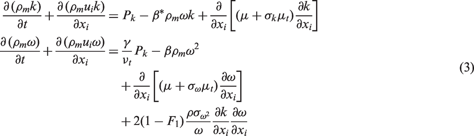
SST (Menter’s Shear Stress Transport) turbulence model
13

And boundary and far field conditions:
Cavitation model
The full cavitation model developed by Singhal et al.
7
assumes the working fluid to be a homogenous mixture of liquid, vapor, and non-condensable gas (NCG), i.e., all three fluids are assumed to be in both mechanical and thermal equilibrium (equal velocity and equal temperature) at each location in the calculation domain. The convection and diffusion equations of the cavitation model are employed to depict the fluid density. Here, the mixed fluid density is a function of vapor mass fraction fv, which is computed by solving a transport equation coupled with the mass and momentum conservation equations


The densities ρv and ρl are functions of saturation pressure and temperature, which are constant for isothermal flows. The density of NCG ρg is calculated as a function of local pressure, by using the ideal gas law, i.e.,

Then, volume fraction of NCG and liquid will be
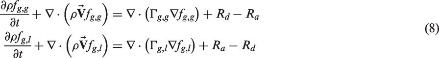
The NCG mass fraction can be split into two components, gaseous state and dissolved liquid state. Accordingly, two more convection-diffusion equations are introduced for describing their phases: one for NCG in gaseous phase, fg,g, and another for NCG in dissolved liquid phase, fg
.l
(note that the mass fraction of the liquid itself is simply fl).

The total mass of NCG is conserved in the computational domain, which can be seen by adding equation (8). The source terms Rd and Ra link the exchange between the two states. The rate expressions for desorption and absorption of NCG depend on the local partial pressure of NCG in gaseous state, an equilibrium pressure for NCG in dissolved state, and the local mass fraction of NCG. The corresponding expressions are

Grid generation and boundary condition
For the purpose of comparing with the results of experiment, a miniature experiment model which has been used in hydrodynamic tunnel is selected as computational model in this paper. It is a slender body with a disk cavitator whose diameter is Dn. The length of the whole computational model is L and the maximal cylindrical diameter D. Tri-ventilated hole is located in the downstream from the cavitator. The specified shear wall boundary condition is used which denotes the tunnel. The main boundary conditions of the model are shown in Figure 1. Trivial distorted scale in Figure 1(b) and (c) is modified for better display.
Region and grid of the computational model. (a) Scheme of the computational model; (b) grid generation and boundary condition; and (c) detail of grid near cavitator (distorted scale).
Results and analysis
Entrainment rate
Ventilated supercavitation flow past a disk cavitator with sharp edge is typically encountered in hydrodynamic tunnel for investigate supercavitating flow and has received lots of attention as an effective method to generate supercavity.
In order to reduce the drag acting on the underwater vehicle, a well-defined cavity shape must be designed carefully, and the cavity size must be large enough to accommodate the vehicle. It is well known that the cavity shape depends principally on the cavitation number which is the most important parameter for ventilated supercavitation.

Here, it is necessary to remark that the definition of the cavitation number in the form of equation (10) is useful for the steady cavity because the numerator, p∞-pc, is the pressure tending to close the cavity and the denominator, 0.5ρv∞, 14 is the dynamic pressure effective in resisting this closure.
The main problem for the ventilated cavity flows is a problem on the gas quantity necessary for supply into the cavity to keep the supercavitation of given dimension. 15 There are usually essential differences between the natural and ventilated supercavity. In natural or vaporous cavitation, evaporation from the cavity wall can furnish the vapor loss from the cavity tail, but in the case of the ventilated supercavity, the artificial ventilation rate must be in equilibrium with the rate at which the gas is entrained away. For a vehicle with large slenderness ratio, and therefore a large supercavity, a small cavitation number is necessary, which normally cannot be achieved by natural cavitation, where the cavity is filled with vapor, but requires the furnish of air or gas into the cavity. For the ventilated supercavity, it is of obvious interest to know the demanded quantity of gas.
The dimensionless parameter called the entrainment rate is introduced.

Figure 2 gives some typically numerical results of tri-dimensional ventilated cavity shape with the entrainment rate ranging from 5.6 to 6.8. Shown in transparent gray is a cavitation bubble shape (associated with a multiphase iso-surface that is 50% liquid and 50% gas). Qualitatively, as can be seen from Figure 2, the cavity dimension increases while increasing quantity of gas supply. This phenomenon is consistent with the results of experiments performed in hydrodynamic tunnel.
Some typical numerical results of ventilated cavity shape.
A series of experiments of ventilated supercavitation were also carried out in the high-speed hydrodynamics laboratory of Northwestern Polytechnic University in China (NWPU). Figure 3 shows the comparison of cavity shape between simulation and experiment. Evidently, the cavity has an approximately ellipsoidal shape if gravity effect is negligible. As far as the cavity shape is concerned, the computational results successfully show the whole property of cavity, but it is not thick as compared with the results of experiment, especially near the cavitator. In addition, because of gravity, the cross section of supercavity attached to the cavitator tends to rise monotonously a distance which depends on the distance downstream from the cavitator.
Comparison between computation and experiment (NWPU hydrodynamic tunnel). (a) Numerical result (CQ = 5.6); (b) experimental result (CQ = 5.6); (c) numerical result (CQ = 6.2); (d) experiment result (CQ = 6.2); (e) numerical result (CQ = 6.8); (f) experiment result (CQ = 6.8).
The permanent gas enters into cavity and results in the increasing of the cavity dimension and in the decreasing of the magnitude of cavitation number. When the gas concentration is sufficient, the supercavity dimension increases considerably since the cavity can also absorb part of gas from the gas–liquid bubble multiphase flow. It is impracticable to measure cavity length directly because of the gas leakage at the wake of cavity closure and the large aspect ratio of the slender body selected, while diameter of supercavitation has been measured by choosing the phase iso-surface equal to 0.5. Based on the numerical simulation, the variation of entrainment rate along with the cavitation number, together with the cavity dimensionless diameter, were obtained as shown in Figure 4. In these cases, the cavity pressure pc is treated as the average pressure of cavity and the relative cavity diameter with respect to the disk cavitator diameter Dn is treated as the reference. We can see clearly from the Figure 4 that the cavity diameter Dc increases monotonously with increasing the quantity of gas supply.
Computational results of entrainment rate.
Drag coefficient
The supercavitating drag reduction is one revolutionary technique for submerged vehicles. The most fascinating property of supercavity is that it can help us to break the conventional speed barrier, although its occurrence may cause to significant hydrodynamics attribute in the cavity flow. Underwater vehicles exploit supercavitation as a kind of means to reduce drag and achieve dramatically a super-high traveling speed, in this case supercavity covers the entire length of vehicles. The drag coefficient is defined as

Figure 5 gives the drag coefficient as the function of cavitation number according to the result of numerical simulation. The ventilated supercavitation regime corresponds to small magnitude cavitation number and the friction drag coefficient is significantly lower than the pressure drag one. The reason for this is that the supercavity occurs as if the diameter of underwater vehicle increases and as if the vehicle completely travels in air.
Drag coefficient and cavitation number.
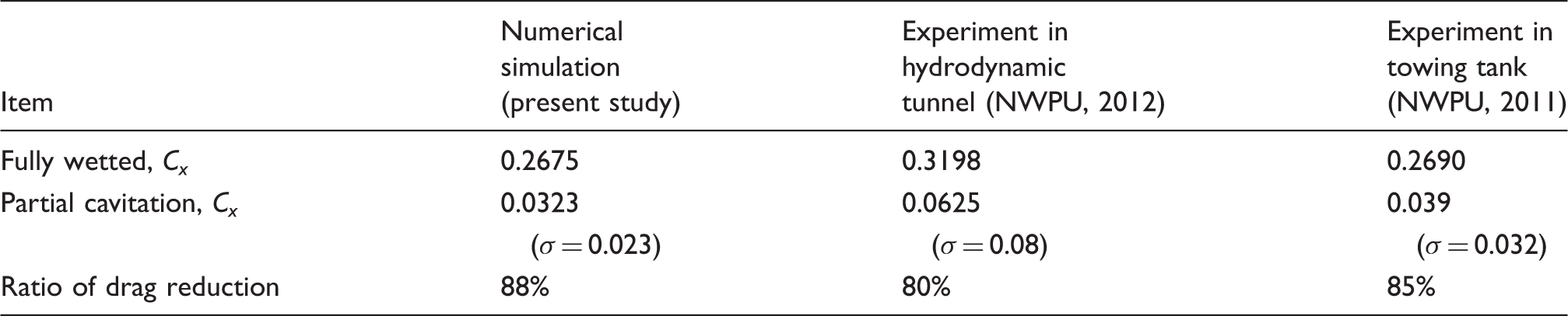
Figure 6 gives the measured results of the experiments performed in the high-speed hydrodynamic tunnel and in the towing tank, respectively. The comparison result between the numerical simulation and the experiment is shown in Table 1. The percent of drag reduction is calculated by the ratio of the difference between cavitating condition and fully wetted condition. The numerical result is in reasonable agreement with the experiments.
Drag reduction results of the experiment. (a) Drag reduction of the experiment under NWPU hydrodynamic tunnel (σ = 0.08); (b) drag reduction of the experiment under the towing tank (σ = 0.032). Maximal drag coefficient results of experiment and numerical simulation.
Effects of gravity
Each of the three references16–18 provides some useful information for hydrodynamic design of underwater supercavitating high-speed vehicle. In this part, we draw on information provided by literature16–18 and present comprehensively numerical and experimental results of such design. In order to check the validity of our proposed design, we planned carefully water tunnel model experiments and carried them out in NWPU high-speed water tunnel. One point we wish to emphasize is that we paid special attention to the generation of non-symmetrical supercavitating zone to satisfy the balance and stability of underwater supercavitating high-speed vehicle. Photographs of cavity flow pattern of vehicle and hydrodynamic curves obtained in the experiments indicate preliminarily that our proposed design principles and methods are feasible.
Supercavity generated in flows past the submerged obstacle is normally in the gravity field that affects the cavity flow and distorts it. For the case of artificial supercavitation, which can be easily obtained at small magnitude of the mainstream velocity when the cavitation number holds the same value as the case of the natural supercavity, the gravity effects are considerably important. It causes deformation of the cavity shape, i.e., the moving-upward of the ventilated cavity tail. 16
Qualitatively, the distortion is due to the greater rise of the bottom than of the top of the cavity near its downstream end. The ideal ellipsoid of the cavity shape is unrealistic. The reason for this is that if the cavity has such an ideal ellipsoid shape just like the rigid body, the flow distribution would be the same as the flow about that rigid body. However, this assumption is inconsistent with the requirement of uniform total pressure about the cavity. Since the pressure within a steady cavity is almost uniform, the water must exert a uniform pressure on it. According to the Bernoulli theorem, the flow speed increases with depth. Hence, the local pressure must equilibrate the hydrostatic pressure, which is caused by the submergence depth. Consequently, the cavity is distorted to provide proper velocity distribution in the gravity field. The steady supercavity is fixed at the end where it is generated and the buoyant force causes its downstream portion to float upward until the newly steady position is reached where the net buoyant force vanishes, i.e., the undistorted cavity suffers buoyant force, but the distorted steady cavity does not.
The Froude number is introduced to depict the deformation.
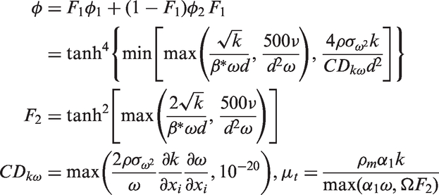
Figure 7 depicts the results of ventilated cavities at small cavitation numbers and the different Froude number ranged from 2.82 to 4.23. The relative cavity deformation is calculated with respect to the whole model length L selected as the reference.
Comparison of results between numerical and experiment of ventilated cavity in gravity field. (a) Computational result (FrL = 2.8); (b) experiment result (FrL = 2.8); (c) computational result (FrL = 3.4); (d) experiment result (FrL = 3.4); (e) computational result (FrL = 4.2); (f) experiment result (FrL = 4.2).
It is usual to relate the change of deformation along cavity length to the square of the Froude number. The approximate formula of cavity axis slope caused by the gravity effect was investigated with the perturbation method by Savchenko and Semenenko
17
and Savchenko et al.
18
who explained that the cavity axis bend increases according to the quadratic law. A schematic of cavity ordinate distortion in the gravitational field is shown in Figure 8.
Schematic of gravitational effect on cavity shape.
Figure 9 gives the numerical results of the deformation in the case of different Froude number. Obviously, the float upwards of the cavity rear increases monotonously along the whole supercavity horizontal length and reaches its maximal value at the end of cavity. The smaller Froude number appears to correspond to a larger deformation. Qualitatively, the simulated results are in reasonable agreement with the experiment performed in the high-speed hydrodynamic tunnel of NWPU.
Relative deformation of cavity axis in gravity field.
Since the gas leakage at the wake of cavity closure and calculated tolerance of interface between liquid and gas in the commercial code, it is difficult to calculate the axis inclination of supercavity. The selection of different iso-surface of the phase may result in a little warp in the magnitude of axis deformation. Here, we select 0.5 as the phase iso-surface. Theoretically, the deformation should become very small at high speed (strictly at high values of Froude number), and this has verified by the experiments in the hydrodynamic tunnel.
Figure 10 shows the experimental result of model equipped with four fins placed symmetrically along the girth of the model near the tail. The four fins help in counteracting moments produced by cavitator and also provide lift to balance the weight and the buoyancy force. It can be seen that there is a small dependence of cavity deformation on Fr. The numerical results indicate that the gravitational effect should disappear almost completely for the Froude number Fr > 7.0, where Fr is based on the model length. The configuration of supercavity then can be regarded as an approximately ellipsoid. However, since the non-symmetry of supercavity is attached to the model, additional equipment and angle of attack must be devised carefully for balancing the longitudinal forces of underwater vehicle. We should note that there must be some discrepancy in both captured cavitation interface and measured deformation hg. So, we must consider our analysis approximately from this point of view. Discrepancy is observed in the transition region due to the unstable gas leakage in this stage. For realistic incident measure amplitudes, the unavoidable discrepancy will be so large that measurement accuracy matters.
Experimental result in hydrodynamic tunnel of model equipped with fins.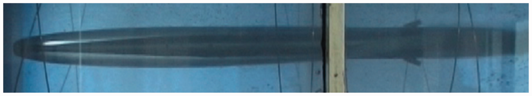
Conclusions
The structural characteristics of ventilated cavity flow are numerically simulated based on the multiphase flow model. The basic similarity parameters of ventilated supercavitating flows are investigated numerically and analysed in much detail. They determine the behavior of cavity flows for a given model. The simulation results show that the cavity number decreases and the dimension of elliptical supercavity increase with increasing of gas supply rate. In addition, the dependence of drag coefficient on the cavitation number are investigated numerically under the condition of small cavitation number; the gravity effect which results in cavity axis deformation is calculated and studied. When the Froude number is very high, the effect of gravity can be neglected. The corresponding results of drag measurements under various hydrodynamic flow conditions in a hydrodynamic tunnel and a towing tank were presented. The results show the promising behavior of supercavitation technique that can substantially reduce hydrodynamic drag, i.e., the value of the drag reduction ratio can up to 90% compared with that of the non-cavitation condition. The friction resistance is considerably lower than the pressure resistance when supercavity occurs. It is possible to envision and design an optimal model system with a series of matching favorable parameters that improve underwater vehicle’s hydrodynamics, guidance, and control performance for experiment or practical application. The results can be research guidance for further high-speed underwater vehicles.
Footnotes
Declaration of conflicting interests
The author(s) declared no potential conflicts of interest with respect to the research, authorship, and/or publication of this article.
Funding
The author(s) disclosed receipt of the following financial support for the research, authorship, and/or publication of this article: The financial support provided by the National Defense Basic Research Foundation of China (K1804061802) and by the Special Fund for Basic Scientific Research of Central Colleges, Chang’an University (CHD2012JC074) is gratefully acknowledged.