
Abstract
The spraying of an impinging jet is an effective way to cool heated surfaces. A numerical model has been previously developed to predict the heat transfer with phase change between a hot plate surface and a two-phase impinging jet. This Computational Fluid Dynamics (CFD) model is applied here for studying the spray cooling of conventional and impregnated coil windings of electric motors. The numerical results are compared with measurements obtained on an experimental test bench. The confrontation numerical/experimental is carried out by comparing the distribution of temperature inside the coil windings. This study has confirmed the interest of the cooling spray technique. The interest to fill coil windings with impregnating resin of good thermal conductivity is less obvious. When using spray cooling, the lowest temperatures are reached within conventional coil windings.
Introduction
This work falls under a research project 1 aiming at improving the heat dissipation and the cooling of electric motors of great power (more than 30 kW) intended for a new generation of electric cars. The need for designing electric motors with higher specific powers obliges to consider very effective cooling solutions such as spray cooling2,3 to cool the high temperature parts of the motor (as the coil winding heads).
A preliminary study has been previously carried out by the present authors4,5 in order to develop a CFD model making it possible to predict the heat transfer with phase change between a heated surface and a two-phase impinging jet. Different two-phase modeling approaches (Lagrangian and Eulerian methods) have been compared. Experimental validation of the numerical simulations has been achieved in the case of a two-phase jet impinging a hot metal surface. It was shown that the two-phase Eulerian model, associated to the Realizable k-epsilon turbulence model, was capable to take into account reasonably the evaporation of the droplets in contact with the heated plate.
In the present study, the Eulerian model is used to study the spray cooling of coil windings of electric motors. A way to improve the dissipation of the heat produced by Joule effect within the coil windings consists in increasing thermal conductivity within the coil windings. For that, a well-known solution consists of impregnating the stator coil windings with resin which thus replaces the stagnant air present in traditional windings. Then, the difficulty lies in the choice of the optimal material of impregnation which must have both good electrical insulation properties and good thermal conductivity to facilitate the dissipation of the heat generated in the coil windings. 6
Two kinds of coil windings are tested in this study: a conventional coil (a concentrated winding around one laminated tooth) and an advanced coil winding impregnated with thermosetting resin. The numerical results are compared with measurements obtained on an experimental test bench.
Experimental setup
The experimental setup is shown in Figure 1. It consists of a heating system, a spraying system, and a data acquisition system. The spraying surface corresponds to the top surface of a coil winding. The coil winding is supplied with a current intensity of 20 A and a voltage of 8 V, corresponding to a current density of 20.31 A mm−2 and copper losses of 160 W. The current density is high according to the background of this study which deals with the cooling of a motor with high specific torque. The winding (except the top surface) is wrapped by thermal insulation material to minimize heat loss and to guarantee unidirectional heat conduction (in the axial direction).
Spray cooling test bench.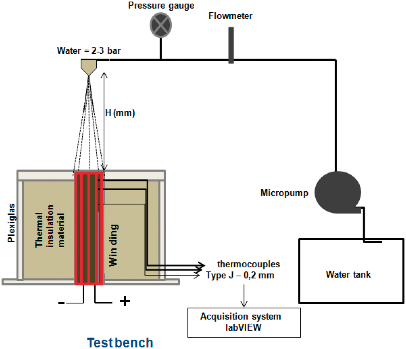
The wound teeth used in the present experiments are identical to those used by the company Phenix International for the manufacture of radial flux permanent magnet motors of 7.6 kW power, which is specially designed for a small urban electric vehicle. Two kinds of coil windings are tested: a conventional coil (a concentrated winding around one laminated tooth) and an advanced coil winding filled with thermosetting resin. The resin used here is the Voltatex 4200 impregnating resin. Voltatex 4200 is a polyester resin, commercialized by DuPont, which has a thermal conductivity of 0.23 W m−1 K−1.
A spray nozzle (Fine Spray Hydraulic Atomizing-type1/4M-SS2—spraying system) with a spray angle of 70° and an orifice diameter of 0.71 mm is used. The spray nozzle is supplied with water at an operating pressure of 3 bar. As specified by the manufacturer, the spray nozzle used produces water droplets of about 214 µm Sauter Mean Diameter at this supply pressure of 3 bar. The water temperature and flow rate are fixed at 40°C and 132 mlmin−1, respectively. During the present experiments, the spray nozzle is positioned at a distance H of 40 mm above and perpendicular to the horizontally placed heated surface.
The cooling analysis is done by following the temperatures at different points inside each coil winding. J-type (iron–constantan) thermocouples, each having a 0.2 mm bead diameter, were implanted at different positions as shown in Figure 2. The first thermocouple (TC-1) is positioned in the coil winding medium. The second thermocouple (TC-2) is positioned between two coils. The third thermocouple (TC-3) is located between the tooth and insulating paper medium. The thermocouple signals are collected using a high-density thermocouple module (NI9213 module) connected to a PC running with LabVIEW.
Thermocouples position.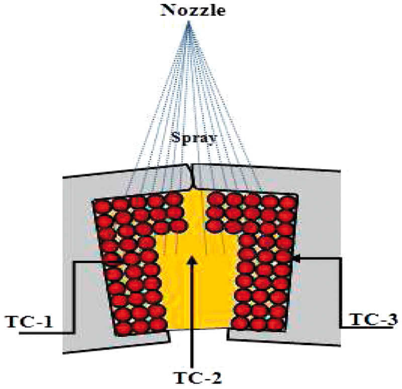
Numerical approach
The computation has been carried out using the commercial CFD software ANSYS-FLUENT. The steady-state simulation uses the pressure-based solver, which employs an implicit pressure correction scheme and decouples the momentum and energy equations. The SIMPLE algorithm is used to couple the pressure and velocity. Second-order upwind scheme is selected for spatial discretization of the convective terms. The turbulence of the flow is taken into account using the realizable k-epsilon model. The two-phase flow phenomenon is modeled using the Eulerian model. 7 This model uses the interfacial area concentration model of Hibiki-Ishii. 7 In this model, one set of balance equations of mass, momentum, and energy is written for each phase. The interfacial area concentration is specified by a transport equation which models the evolution of the geometric structure considering the physical mechanisms of local interactions between the two phases (coalescence and breakup). The transport equation can capture the dynamic changes in the flow structure, especially the transitions among flow regimes. Hence the transport equation can be used for systems with wide range of scales and boundary conditions (boiling flows, bubbly or droplet flow systems, dispersed flow cases, particulate suspensions).
Geometry and mesh have been generated using the preprocessor GAMBIT. Figure 3 shows the 2D axisymmetric computational domain and the boundary conditions used. The bottom of the domain corresponds to the top of the heating cartridge. The spray nozzle exit is located in the top left corner of the domain. The computational domain has been discretized to fine cells to conduct the simulation. Figure 3 shows the computational grid which contains approximately 40,000 quadrilateral elements. To accurately predict temperature gradients and heat transfer, the cells have been clustered toward the impact surface to obtain appropriate y+ value less than 1.
1
Computational domain and mesh grid.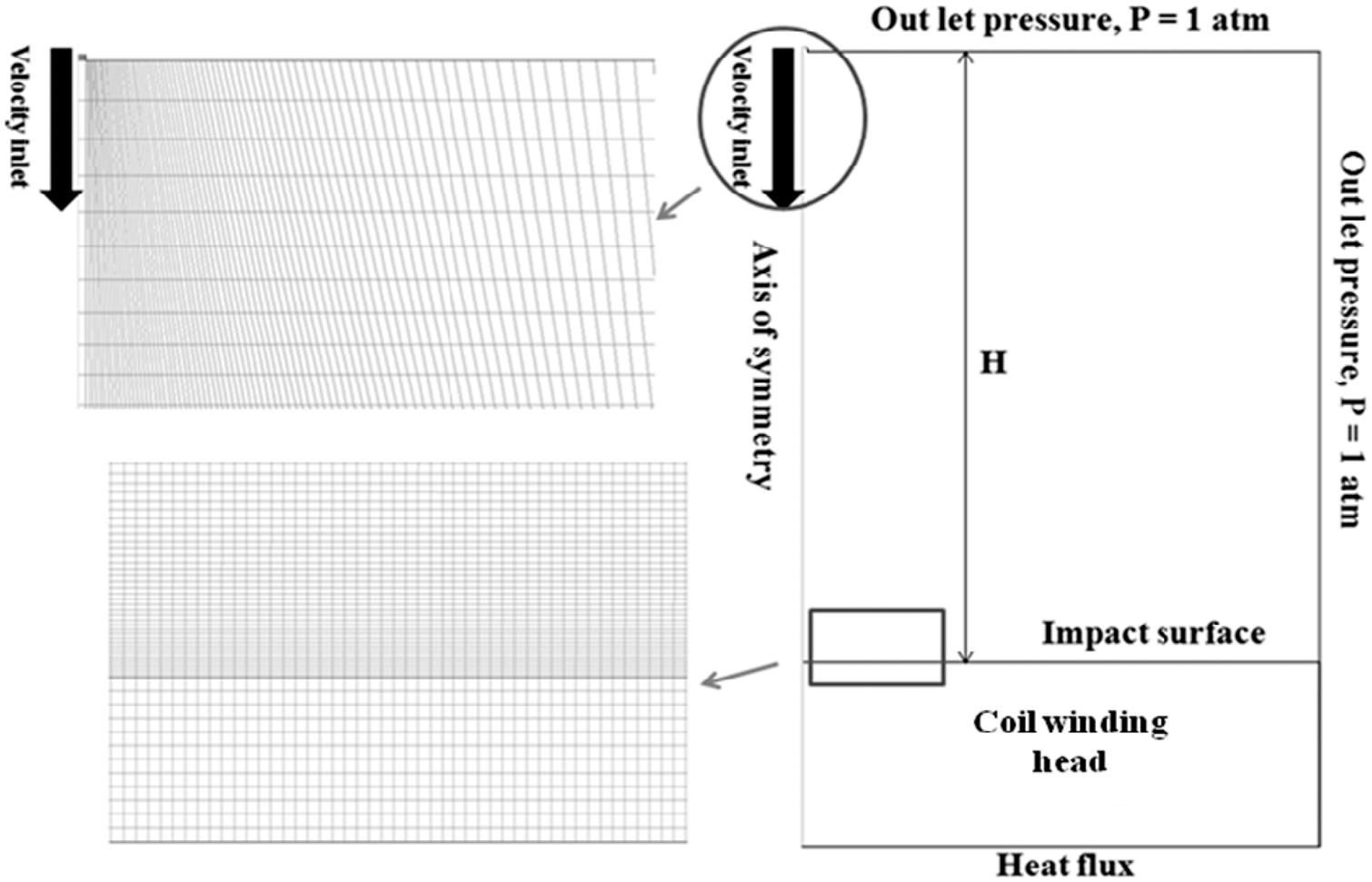
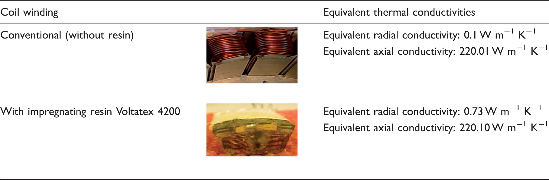
One of the difficulties of this simulation is related to the modeling of the coil winding. The composite structure of coil windings is indeed very complex. It involves an area made of copper conductors, insulation, and air or resin filling the spaces between adjacent conductors. This complex geometry cannot be modeled directly. Therefore, as in most numerical models, the simulation is simplified by replacing the composite structure of the winding with a homogenized material with properly averaged thermal properties. 8
Equivalent thermal conductivities of different coil windings calculated using Milton correlation.
Results
The first result presented concerns the interfacial area concentration calculated using the Hibiki-Ishii model. Figure 4 gives an example of calculated radial distribution (at the impact surface) of this parameter which is a key parameter in modeling the interfacial transfer terms in the two-fluid model.
Example of radial distribution of the interfacial area concentration (in m−1) calculated using the Hibiki-Ishii model.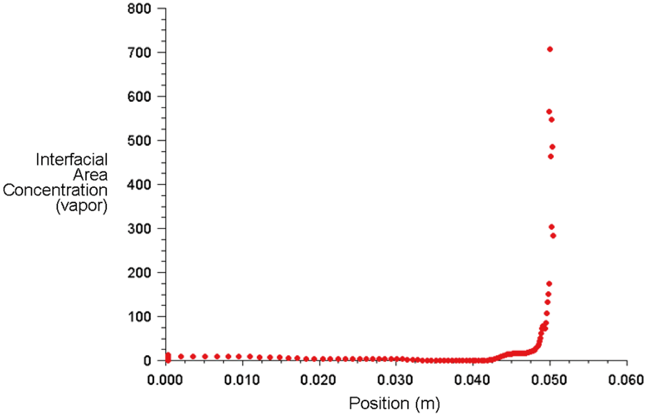
Figure 5 presents results obtained using the conventional coil winding. This figure compares distributions of the temperature inside the coil winding, obtained for free convection and spray cooling modes. In the case of spray cooling, the experimental results are compared with computational results from CFD simulations.
Evolutions of the temperature inside the conventional coil winding for different cooling modes.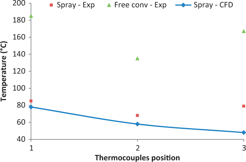
As expected, the temperatures observed with free convection cooling are significantly higher than those with spray cooling. The cooling of the coil winding is significantly improved when using the spray cooling technique. The numerical results are in good agreement with experimental measurements, with the exception of the temperature corresponding to TC-3 thermocouple for which there was a difference of 30°C between the measured and calculated values. This difference can be explained by the fact that this thermocouple is located just after insulating paper whose characteristics are probably poorly addressed by the present numerical model.
Figure 6 is concerned with results obtained using the coil winding filled with resin Voltatex 4200. Again, the temperatures predicted by the CFD simulation are in good concordance with the experiments. The temperature distributions confirm the improved cooling when using the spray cooling technique but to a lesser extent than for the conventional coil without resin. However, all the results presented in Figures 5 and 6 point out the better efficiency of the spray cooling on the free convection cooling mode. The temperature levels achieved using spray cooling remains below 150°C, for both types of coil winding.
Evolutions of the temperature inside the impregnated coil winding for different cooling modes.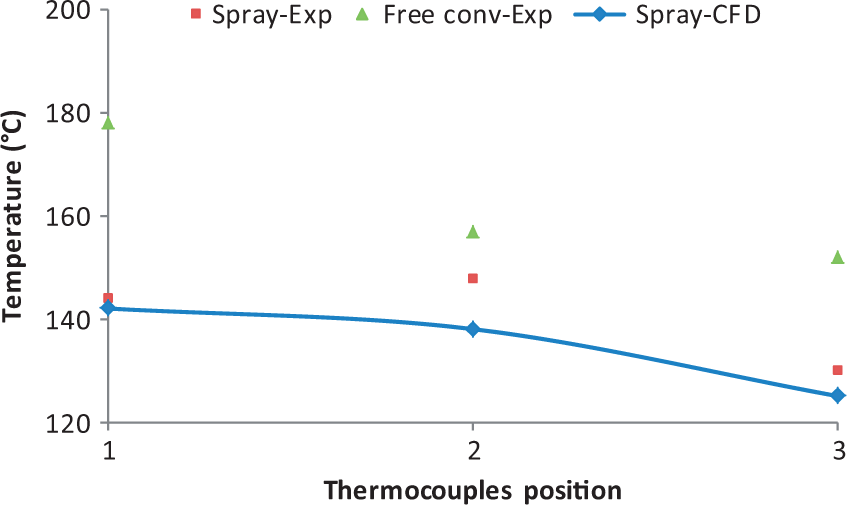
Figures 7 and 8 show the effect of the impregnating resin on the temperature distribution for the two cooling modes considered. The results obtained when the coil winding is cooled by free air convection only (Figure 7) show a nonmonotonic evolution of the temperature inside the conventional coil winding (without impregnating resin). The lowest temperature is measured between the two teeth. When replacing air by resin, the temperatures TC-1 and TC-3 decrease but the temperature between the two teeth is higher than without impregnating resin. This is explained by the fact that the resin, which is a better heat conductor than air, improves the heat transfer by conduction from the coil winding medium and the teeth iron medium. The temperatures TC-1 and TC-3 are thus logically lower than those measured without resin. On the other hand, the thermocouple TC-2 indicates the temperature between the teeth. When the impregnating resin replaces the stagnant air, the gain in thermal conductivity leads to an increase of the temperature at this place.
Evolutions of the temperature inside different coil windings for the free convection cooling mode. Evolutions of the temperature inside different coil windings for the spray cooling mode.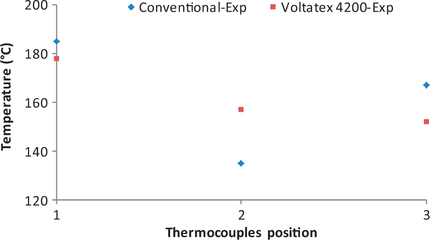
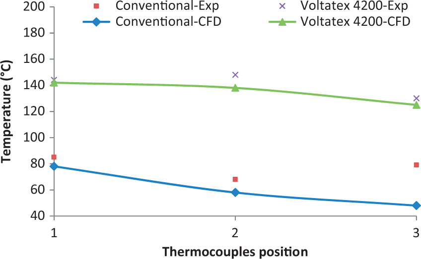
In the case of spray cooling of the coil windings (Figure 8), it appears clearly that the presence of resin is penalizing when using this mode of cooling. Indeed, the lowest temperatures are obtained in the conventional coil winding. This is explained by the fact that the upper surface of the impregnated coil winding is covered by a thin layer of resin which slows down the convective heat exchange at the surface. This limitation is all the more significant that the mode of cooling is effective and that the thermal conductivity of the resin is low. Furthermore, when no resin is used, the liquid part of the spray may infiltrate inside the coil and the evaporation which takes place at the hottest point increases the heat removal capability of the spray.
Conclusion
A CFD model, previously developed to predict the heat transfer with phase change between a heated surface and a two-phase impinging jet, was applied here for studying the spray cooling of conventional and impregnated coil windings of an electric motor. The confrontation numerical/experimental was carried out by comparing the distribution of temperature inside the coil windings. The temperatures predicted by the CFD simulations are in good agreement with the values measured on the test bench.
This study has highlighted the interest of the cooling spray technique. For both tested coil windings, the levels of temperature reached in the coil windings are lower than those obtained with free convection cooling. The interest to fill coil windings with impregnating resin of good thermal conductivity is less obvious. When using spray cooling, the lowest temperatures are reached within conventional coil windings. On the other hand, in the case of cooling by free convection, the replacement of the air by resin may be interesting by limiting temperatures in the coil windings.
A comparison between the heat transfer with and without impregnating resin in the case of a cooling by forced air convection is currently underway. The replacement of water by another dielectric liquid (FC-72 of HFE-7100) is also under study.
Footnotes
Declaration of conflicting interests
The author(s) declared no potential conflicts of interest with respect to the research, authorship, and/or publication of this article.
Funding
The author(s) received no financial support for the research, authorship, and/or publication of this article.