
Abstract
The situations of fluid flow and heat transfer across an array of cylinders have been quite common in fluid dynamics and, particularly, industry applications. One such situation is flow of water over heated cylinders in a tandem arrangement. The flow of water over heated cylinders faces a phenomenon of phase change from liquid (water) to vapor phase (steam).The mechanism of this phase change is studied through a numerical simulation in this project. The Eulerian model is used in the present simulation method to comprehend the multiphase phenomenon. The effect of Reynolds number on the phase change is studied. The phase change of water in an unsteady flow across cylinders has been prominently affected by Reynolds number. Only critical cases have been discussed in this paper. The volume fraction of water and steam is plotted against the position of flow from inlet to exit of the flow domain that is a channel for a particular flow conditions to demonstrate the phenomenon of heat and mass transfer during the flow of water.
Keywords
Introduction
The problems of fluid flow and heat transfer phenomena over array of cylinders are quite prominent in fluid dynamics and industry applications.1,2 These problems give rise to some of the important aspects in fluid dynamics theory such as fluid flow interaction, interferences in flow, vortex dynamics, and a variety of engineering applications such as compact heat exchangers, cooling of electronic equipment, nuclear reactor fuel rods, cooling towers, chimney stacks, offshore structures, hot-wire anemometry, and flow control. The mentioned structures are subjected to air or water flows and therefore experience flow-induced forces which can lead to their failure over a long time. Basically, with respect to the free stream direction, the configuration of two cylinders can be classified as tandem, side-by-side, and staggered arrangements. Quite a few studies on these problems have been carried out analytically, experimentally, and numerically, especially under the configuration of two tandem cylinders for simplicity.
Some of the outstanding research activities in the above field have focused on the effect of spacing between the cylinders on the flow characteristics and heat transfer around them. It was observed that the qualitative nature of the flow depends strongly on the arrangement of cylinders.1,3,4
Numerical simulations of flow over a pair of circular cylinders have been carried out by applying different methods that are mainly based on finite element formulation. Mittal et al. 3 have investigated the problem numerically using a stabilized finite element method and reported their study for the Reynolds numbers (Re) of 100 and 1000 in tandem and staggered arrangements for different spacings and concluded that at Re = 1000 and L/D = 2.5, unlike Re = 100, in which the flow converged to initial steady state after some transience, the shear layers caused instability due to the increased velocity of flow. Increasing the gap to L/D = 5.5, the flow at Re = 100 showed unsteady behavior. They indicated that the Strouhal numbers that are associated with the vortex shedding of the twin cylinders could take on the same value.
The available experimental investigations and numerical simulations demonstrated rich hydrodynamic phenomena for the problems of fluid flow over double circular cylinders.
In addition to the early experimental investigations, many researchers studied this problem by using numerical simulations. Considering the low Reynolds number Re = 100, Ljungkrona et al. 5 reported two flow patterns for the laminar flow over twin tandem circular cylinders. For the large spacing ratio (L/D > 3.0), the vortices are observed to be shed from both twin cylinders. However, for small spacing ratios (L/D < 3.0), the vortex shedding is observed for only the cylinder downstream, and the vortices in the near wakes of the two cylinders rotate in the same direction, but they are slightly out of phase.
In this respect, wake interaction between two circular cylinders in tandem and side-by-side arrangements was studied experimentally by some researchers such as Zhang and Melbourne, 6 Bearman and Wadcock, 7 Liu et al., 8 and Ryu et al. 9 In their experimental work, Bearman and Wadcock 7 applied a flow visualization method to study the effect of interference between two circular cylinders in side-by-side arrangement at Re = 2.5 × 10⁴. At low Reynolds numbers, Liu et al. 8 employed also the unstructured spectral element method to investigate the flow pattern of two side-by-side cylinders for different spacings.
In the meantime, the flow pattern for tandem arrangement was recently studied numerically by Mahir and Altac, 10 Singha and Sinhamahapatra, 11 Ding et al., 12 and Kitagawa and Ohta 13 for both laminar and turbulent regimes. Deng et al. 14 performed a numerical study on three-dimensional (3D) effects in the wake of two-fixed tandem cylinders at Re = 220. They used the virtual boundary method to apply the no-slip condition. Like two-dimensional (2D) case, they found the critical spacing range for which instability occurred at 3.5 ≤ L/D ≤ 4, implying that for L/D ≤ 3.5, the flow wake maintained a 2D state, while for L/D ≥ 4, 3D effects appeared in the wake.
As a matter of fact, few numerical works have been done on flow over a pair of cylinders at high Reynolds numbers. One of the most recent significant studies involves 3D simulation of flow over two tandem cylinders at the subcritical Re = 2.2 × 10⁴ by Kitagawa and Ohta. 13 They changed the gap from 2D to 4D and analyzed the interference effect and vortex interaction of the two cylinders. Their results showed good agreement with the experimental data at the same Reynolds number. Of noticeable experimental works at subcritical Reynolds numbers, one can mention the studies of Ljungkrona et al. 5 at Re = 2 × 10⁴ and Moriya et al. 15 at Re = 6.5 × 10⁴. They thoroughly investigated the flow characteristics of two tandem cylinders.
Zdravkovich 16 summarized the drag forces, pressure distribution, velocity profile, vortex shedding frequency, and flow patterns for the twin circular cylinders in a tandem arrangement.
The above literature review has encouraged the authors to contribute towards understanding the phase change phenomenon, while water is flowing over two circular cylinders of equal diameters and in tandem arrangement by changing Reynolds number of the flow.
The fluid flow over a single cylinder is amply covered by much literature in the past and hence this has motivated taking up of a situation where there is more than one cylinder. Before taking up of a problem where two-cylinder arrangement is considered, it is felt that the approach and essence of this research will be incomplete without solving a flow over a single cylinder. To validate a few outcomes of the flow over a single cylinder, leading literature was reviewed and results of laminar flow (Re = 200) over a single cylinder is presented here in this paper.
The fluid flow (either laminar or turbulent) over these cylinders with certain heat flux is more relevant as far as the challenges of phase change are concerned. In the present case, it is deemed appropriate to attempt to simulate numerically the phase change phenomenon. This attempt would throw light upon the various challenges and opportunities of phase change from water to steam in a simple case like two-cylinder arrangement in a tandem arrangement. This is kept as one of the objectives for a faster understanding of the physics of phase change.
The impact of Reynolds number on the overall energy and momentum transfer through the fluid flow is noted by volumetric change of water and steam inside the channel. The faster movement of molecules of water and quicker advection signify how two different phases re-orient themselves in terms of volume fractions of each phase.
Physical problem and modeling of trapezoidal cavity receiver
Set up
A sketch of the numerical set up (shown in x–y plane) for two circular cylinders in tandem arrangement with boundary conditions is shown in Figure 1. The necessary dimensions of the fluid domain are expressed in terms of the diameter (D) of the cylinder. The diameters of both the cylinders are the same. The components of the fluid velocity (U) are u, v in the x-, and y- directions, respectively. Here T is the temperature which has a free stream value at the inlet of the flow (left to right in the flow domain) and it is equal to the wall temperature specified at the boundary of the solid surfaces of both cylinders. Water enters at the left inlet and comes in contact with fixed Cylinder 1 and fixed Cylinder 2 with a distance of ‘S’ between them.
Sketch definition of numerical set up (shown in x–y plane) for two circular cylinders in tandem arrangement with boundary conditions.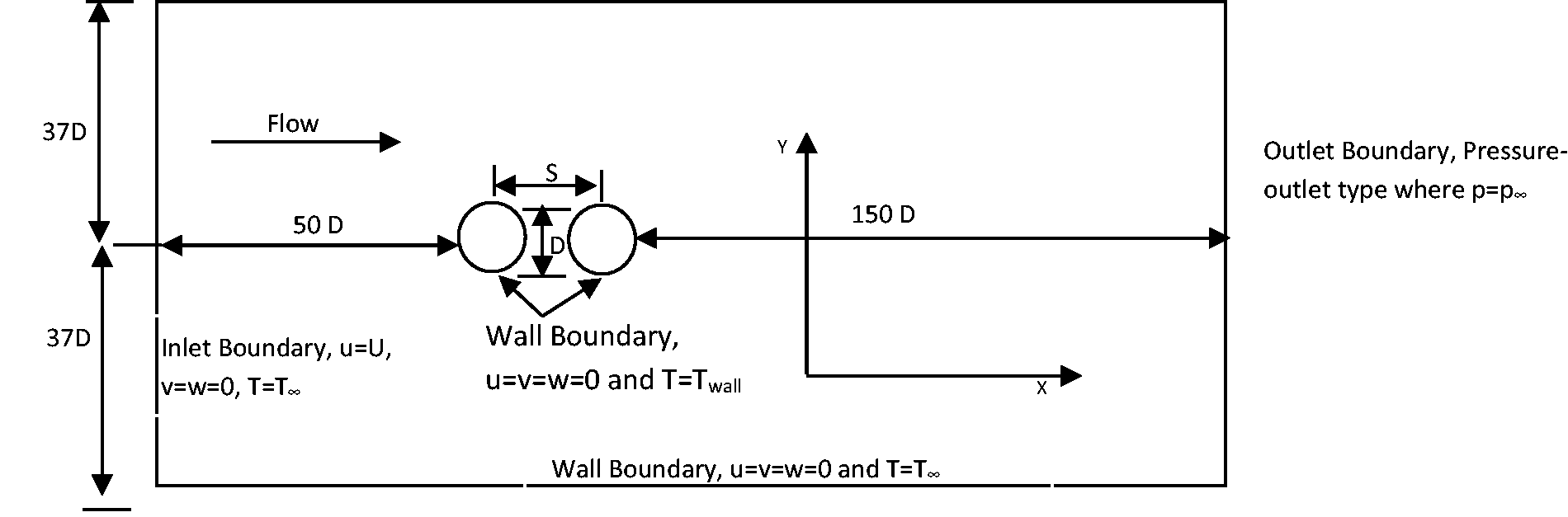
Mathematical modelling
The Eulerian model has been adopted in the current problem.
16
In this model, a set of
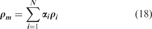
The description of multiphase flow as interpenetrating continua incorporates the concept of phasic volume fractions, denoted here by
The volume of phase ‘q’ is defined by Vq
The effective density of phase q is
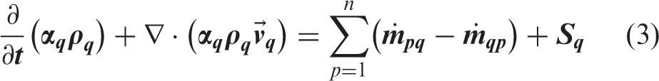
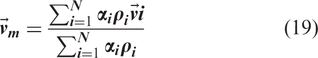
The Eulerian multiphase model allows for the modeling of multiple separate, yet interacting phases. A set of conservation equations for momentum, continuity, and (optionally) energy is individually solved for each phase.
The basic set of governing equations used to solve the multiphase flow problem is given below.
The general conservation equations for conservation of mass, conservation of momentum, and energy are presented below
Conservation of mass
The continuity equation for phase q is
Conservation of momentum
The momentum equation for phase
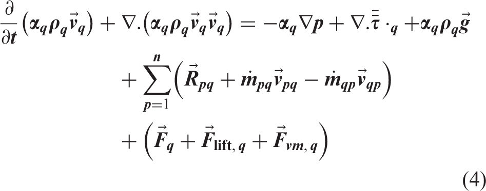
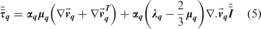
Equation (4) must be closed with appropriate expressions for the interphase force,
Here a simple interaction term is used stated below
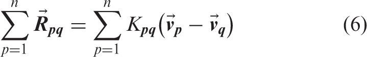
For fluid–fluid flows, each secondary phase is assumed to form droplets or bubbles. This has an impact on how each of the fluids is assigned to a particular phase. For example, in flows where there are unequal amounts of two fluids, the predominant fluid should be modeled as the primary fluid, since the sparser fluid is more likely to form droplets or bubbles. The exchange coefficient for these types of bubbly, liquid–liquid or gas–liquid mixtures can be written in the following general form
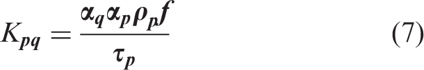
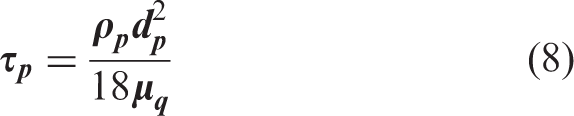
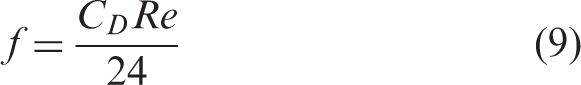
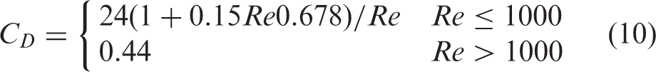
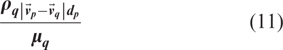
The drag function
Nearly all definitions of
For all these situations,
The Schiller and Neumann model
17
is the default method, and it is acceptable for general use for all fluid–fluid pairs of phases and hence
Lift forces
For multiphase flows, the effect of lift forces on the secondary phase particles (or droplets or bubbles) is included. These lift forces act on a particle mainly due to velocity gradients in the primary-phase flow field. The lift force will be more significant for larger particles, but for simplified analysis, it can be assumed that the particle diameter is much smaller than the interparticle spacing. Thus, the inclusion of lift forces is not appropriate for closely packed particles or for very small particles.
The lift force acting on a secondary phase p in a primary phase q is computed from Drew and Lahey.
18

The lift force
The computation of lift force and drag force is computed for the cylinders by the solver. However, the effect of lift force is assumed insignificant compared with the drag force and hence is not included.
Virtual mass force
For multiphase flows, the model includes the “virtual mass effect'' that occurs when a secondary phase
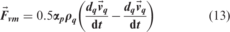
The term
The virtual mass force
Virtual mass force is not considered in the current problem because the relative acceleration between the secondary phase (vapor) and the primary phase is neglected.
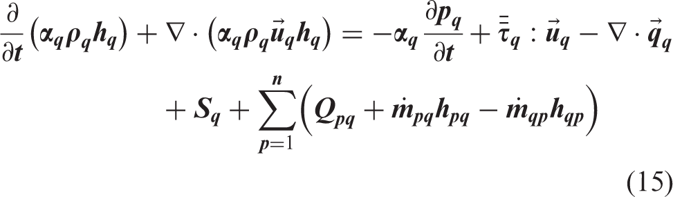
Conservation of energy
Conservation of energy in Eulerian multiphase applications. The current problem uses this form of the equation
Turbulence models
In comparison with single-phase flows, the number of terms to be modeled in the momentum equations in multiphase flows is large, and this makes the modeling of turbulence in multiphase simulations extremely complex. In the present problem,
The
mixture turbulence model
The mixture turbulence model is the multiphase turbulence model which has been used in the present computation. It represents the first extension of the single-phase
The k
and ε equations describing this model are as follows
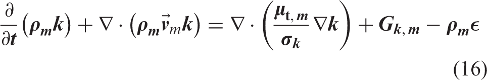
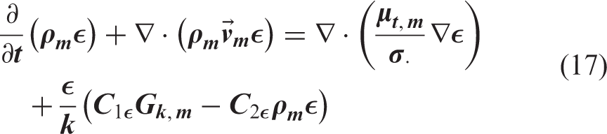
The turbulent viscosity,
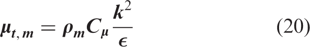

The constants in these equations are given below for the single-phase k–ε
model. The same constants are used while solving the equations for each phase.

Boundary conditions
Boundary conditions for the above set up are as follows:
Inlet to the domain: Velocity inlet, U∞ = 1 m/s. Outlet from the domain: Gauge pressure outlet, p = 0 pascal. Wall of the domain: No slip wall boundary (top and bottom). Cylinder wall surface: Heat flux, q″ = 10,000 W/m2 (for both the cylinders). Cylinder 1: Stationary wall. Cylinder 2: Stationary wall.
Solution procedure and mesh independence study
The continuity, momentum, and energy equations are solved as per the Eulerian model for multiphase using Ansys(R) Fluent 12.1 solver. 16 The phase coupled SIMPLE method has been chosen in the solver to compute the flow variables. The turbulent quantities k and ε are solved as per the mixture turbulence model. The descriptions of both are given in the above section. The iteration of all the steps ends when the full convergence is achieved. Residual values include the momentum equations for each phase, k and ε equations for each phase, and pressure correction residual for continuity equation.
During the heat transfer from the walls of the cylinders to water, which is liquid, it starts to go to a new phase, steam. The mechanism of heat and mass transfer from water to steam is set during the multiphase flow settings. The mass transfer from Phase 1 (water) to Phase 2 (steam) is computed using the unidirectional mass transfer mechanism option in Fluent. Momentum, energy, and turbulence are also transported with the mass that is transferred.
The convergence of the numerical solutions is obtained from the above-mentioned problem using the residuals of the values of variables such as continuity of the flow, velocities of two phases (primary and secondary), and the energy of each phase, turbulent kinetic energy, and its rate of dissipation. In this work, convergence occurs when the values of total residual in all the above-mentioned equations become smaller than 10−5. All these values have reached their acceptable steady solutions during the simulation. The solutions are also independent of the mesh resolution. For the present simulation, initial mesh elements are 306,550 and the convergence of residual error is below the above-mentioned value. The mesh elements are increased to 1.5 times due to finer meshing. The simulation is again carried out and convergence criteria satisfied. The values of all field variables obtained from the two simulations are compared and found to be the same.
Grid quality has been satisfactory after checking the skewness as 0.2 and over all grid quality 0.92 (the highest value is 1.0). The automatic gridding method of the Ansys workbench has optimized the grid density appropriately to fit into flow domain and overall grid quality.
Results and discussion
Verification of the code
First of all, the mean drag coefficient, mean lift coefficient, and Strouhal numbers of the isolated circular cylinder have been compared with those of the other researchers as mentioned in Table 1. The mean drag coefficient versus Re of the flow is plotted in Figure 2. The comparison of the present values of mean drag coefficient with the previously published data is fairly good.
Comparison of mean drag coefficients for various Reynolds numbers for a single circular cylinder. Comparison of the mean drag coefficient
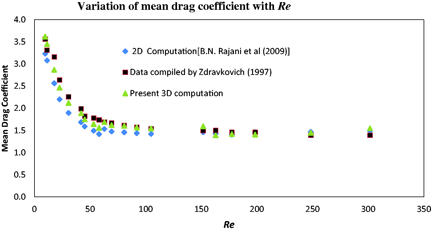
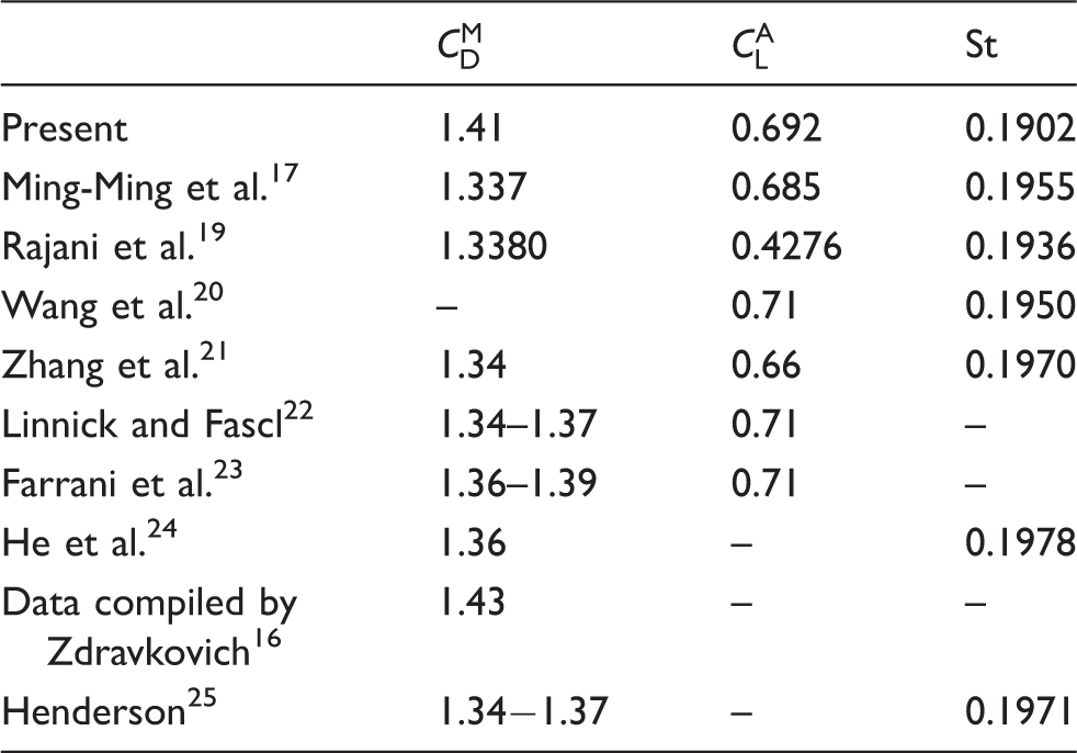
Figure 3 is a plot of Strouhal number which confirms that flow is oscillating and it gives a frequency distribution of vortex shedding from the cylinder. These results are taken for Re = 200. The comparison and the validation of the approach have encouraged the authors to continue studying the flow variables when there is a flow over two heated circular cylinders.
Strouhal number of vortex shedding from the isolated cylinder.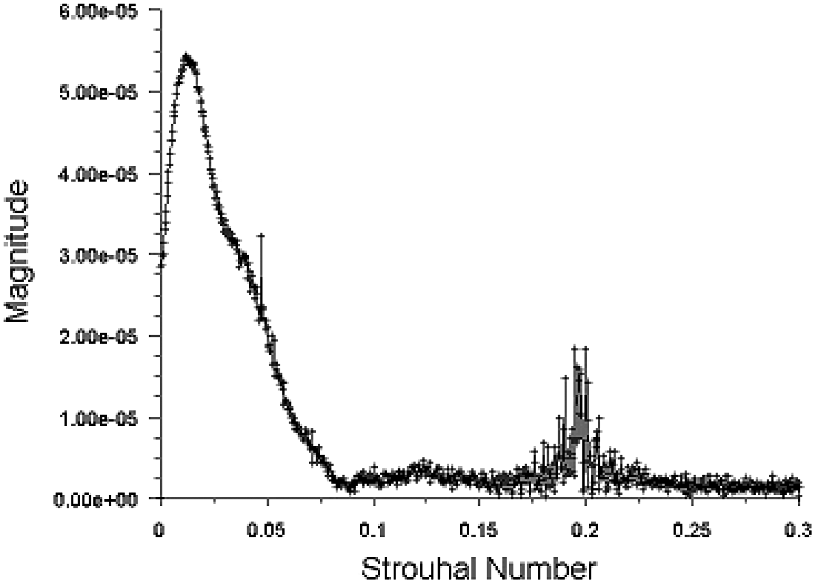
Mean drag coefficient,
The spacing between the centers of cylinders is expressed in terms of the diameter, D. The numerical experiments are done at different Reynolds numbers of the flow and spacing is kept fixed meter. The study aims to observe the motion of different phases in the wake of the cylinders when there is an interaction between the flows of the cylinders and while the flow becomes non-interacting for a gradual increase of Reynolds number.
Basically two Reynolds numbers are considered in this study for a spacing between the two cylinders. Both the cylinders, having the same diameter and length, are heated and the heat flux is maintained at 10,000 W/m2. The heated cylinders are kept in a tandem arrangement at two different spacings: 1.5 D and 6 D. At a particular spacing, water is allowed to flow across the cylinders and its phase change is observed. Two values of Re are considered for each spacing. One value of Re is 200 (laminar flow) and the other value is 1.5 × 10⁵ (turbulent flow). The aim of the numerical experiment is to note and analyze the volume fraction of each phase (liquid and vapor) when water flows at a Re over two the heated cylinders kept at a spacing (1.5 D or 6 D). The inlet temperature of the water is 300 K. During the study, it is also noted that the surface heat transfer coefficients of the heated cylinders get affected by the variation of Reynolds number. An empirical correlation (h = q/ΔT) is adopted for the computation of surface heat transfer coefficients, where q is amount of heat transferred (heat flux, W/m2), h is heat transfer coefficient (W/m2.K), and ΔT is the temperature difference between the solid surface and surround fluid area, K.
Some of the results reported herein include the phase change and the corresponding volume fractions of two phases of the fluid.
Effect of the change of Reynolds number of flow
From Figures 4(a) and (b) and Figures 5(a) and (b), it is observed that, for Re = 200, the volume fraction of water for two spacing (1.5 D and 6 D) differs significantly. The same is true for the volume fraction of steam.
Contours of volume fraction of water and steam when Re = 200 and gap = 1.5 D: (a) water, (b) steam. Contours of volume fraction of water and steam when Re = 200 and gap = 6 D: (a) water (b) steam.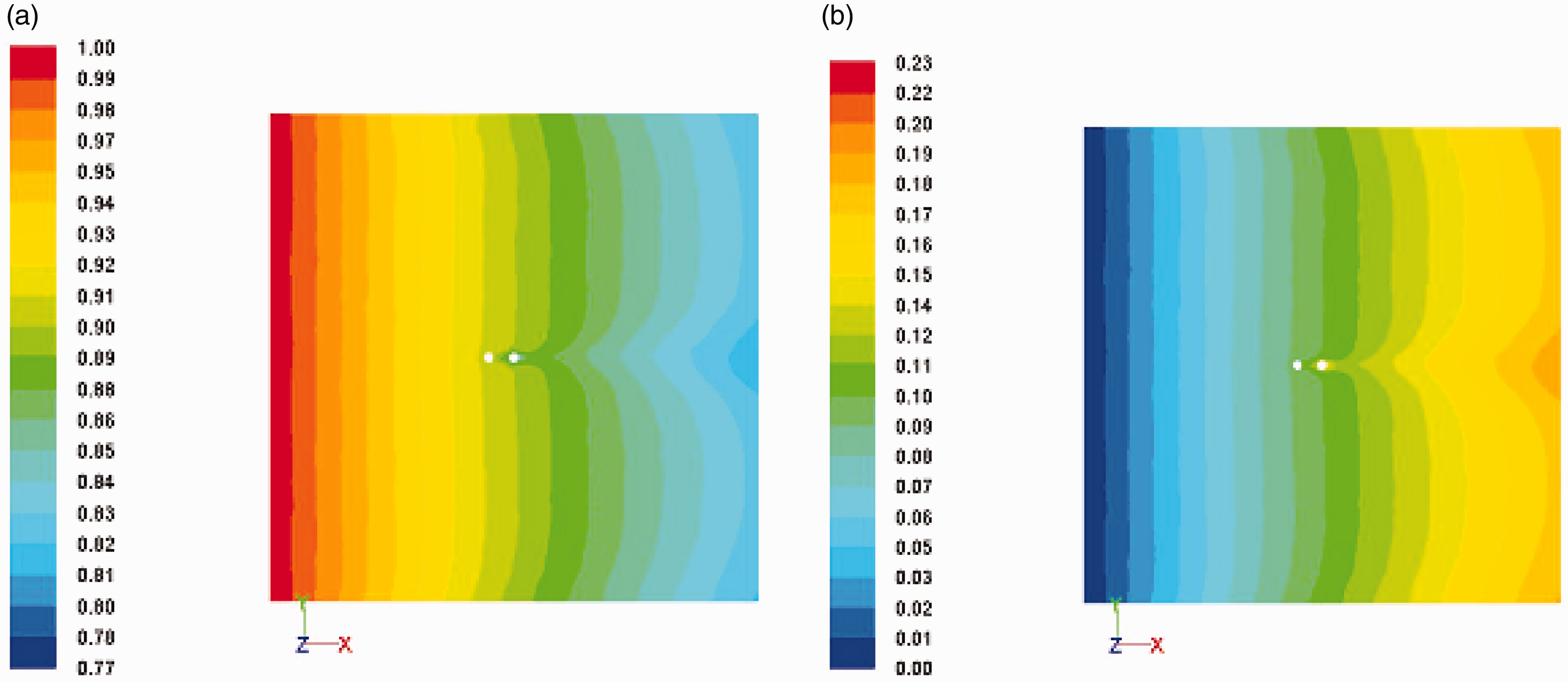
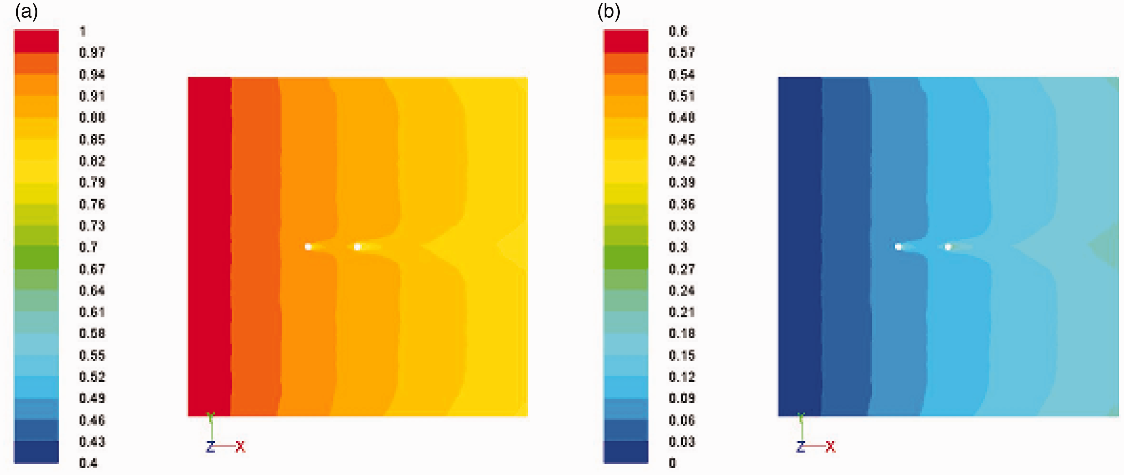
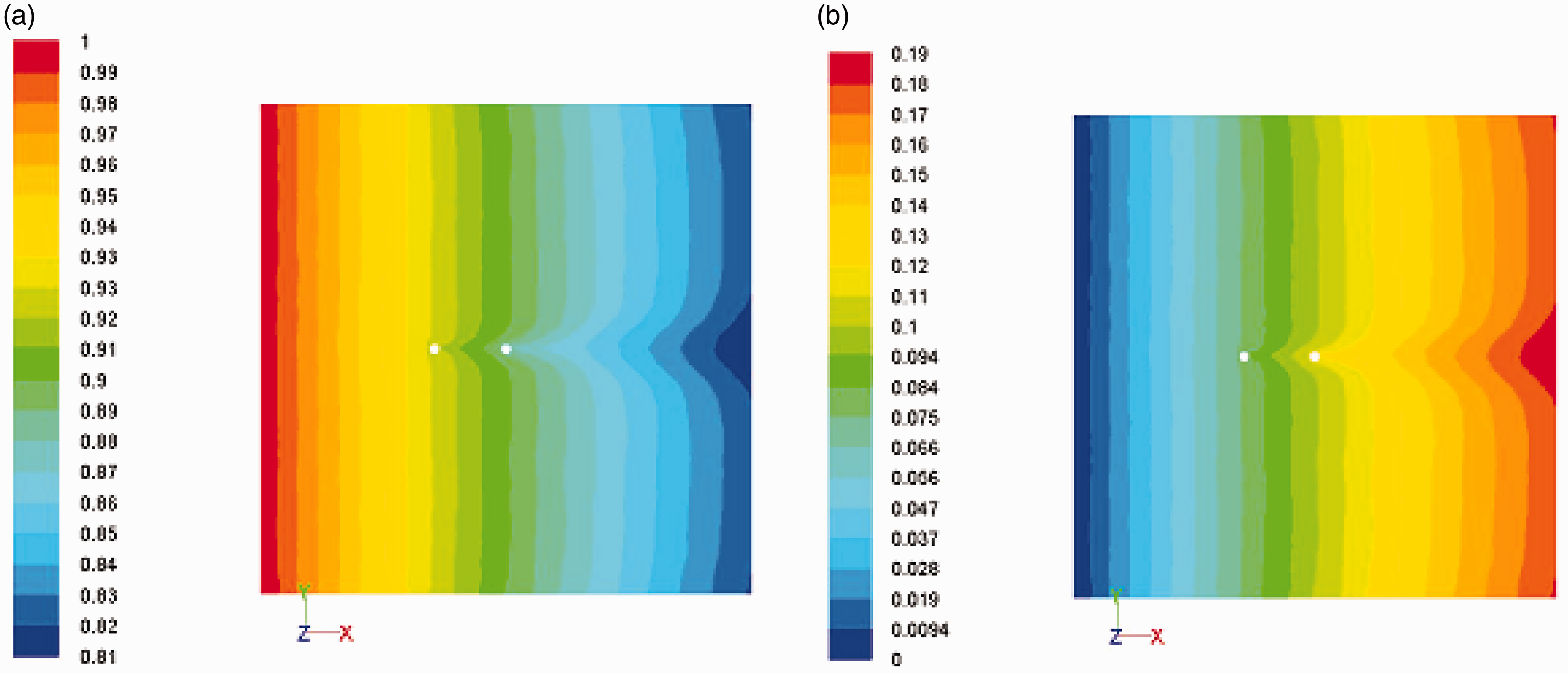
From Figures 6(a) and (b) and Figures 7(a) and (b), it is observed that, for Re = 150,000, the volume fraction of water for two spacings (1.5 D and 6 D) has almost the same value. The same is true for the volume fraction of steam.
Contours of volume fraction of water and steam when Re = 150,000 and gap = 1.5 D: (a) water, (b) steam. Contours of volume fraction of water and steam when Re = 150,000 and gap = 6 D.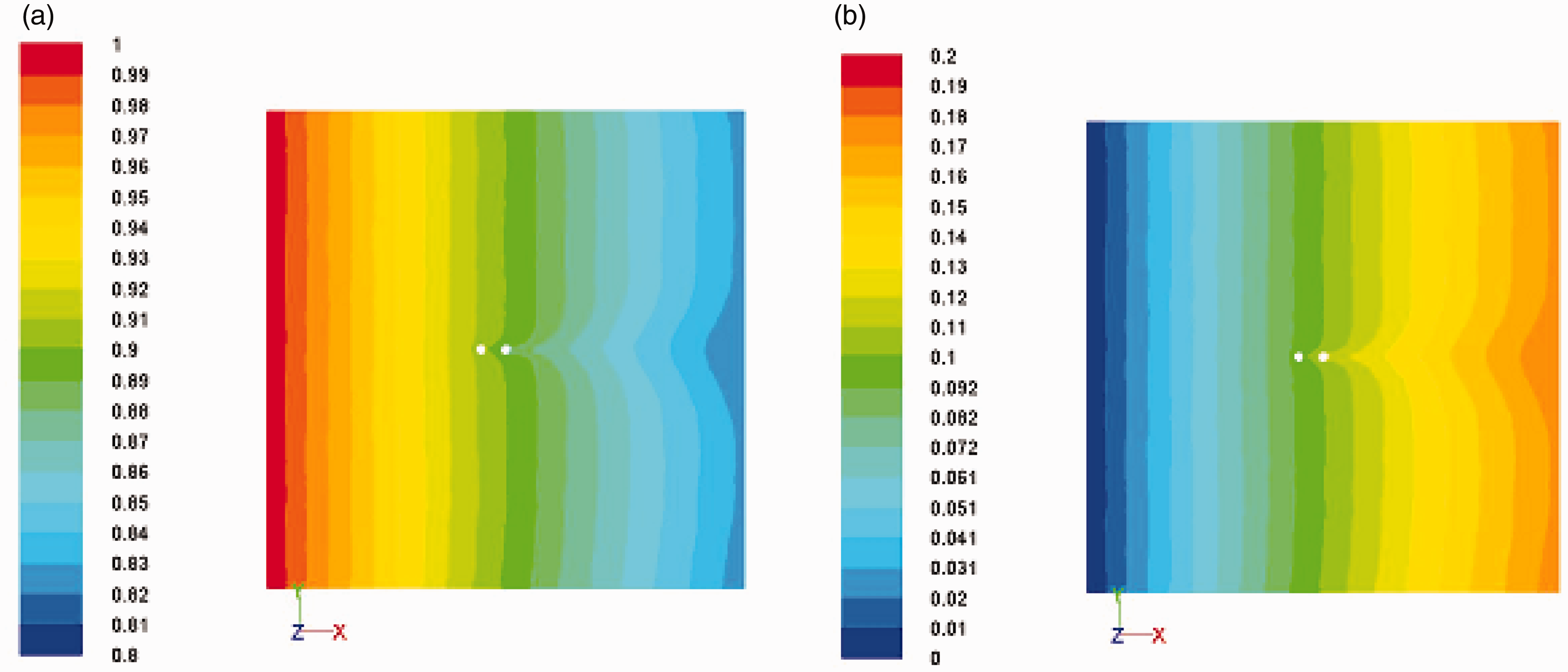
The possible reason for such an observation in the case of Re = 200 could be the availability of more heat flux to water while it is flowing across two cylinders kept at 1.5 D. The volume fraction of water is reducing faster, whereas the volume fraction of steam is increasing when the flows are interacting and are extracting more heat from the both surfaces and lending it to the water present near to the surface.
The widening of the gap increases the scope of accumulating heat for a quicker conversion of water to steam. The maximum volume fraction of steam generated when the spacing is 1.5 D is increased by 61% compared with same value of steam when spacing is 6 D.
Another possibility is that the lower Re allows more resident time for water to be in touch with the heated surface of the cylinder and hence the higher value of volume fraction of steam in the flow domain. The larger spacing alters the opportunity of absorbing more heat by water from the heated surface.
For Re = 150,000, it is observed from the contour plots in Figures 5(a) and (b) that the value of the volume fraction of steam for both the spacings (1.5 D and 6 D) shows a difference of 5%. So, this could be a poor heat and mass transfer phenomenon between the two phases and a weak heat convection (low heat transfer coefficient) from the heated solid surface to water. The turbulent flow (Re = 150,000) has decreased the opportunity for water to stay longer and closer to heated solid surface and it has resulted in a lower value of volume fraction of steam.
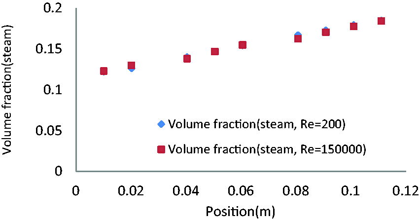
Figures 8 and 9 are the plots of the volume fraction of water versus position in a stream-wise direction and a plot of volume fraction of stream versus position in stream-wise direction when Re = 200 and 150,000 at spacing = 1.5 D, respectively. The difference in the value of volume fraction is observed at locations x = 0.07 m, 0.08 m for the two different Reynolds numbers, respectively. These two locations are near the solid walls of the cylinders. The lower value of volume fraction for Re = 200 and the higher value of volume fraction for Re = 150,000 are justifying the logic that more heat transfer has occurred at Re = 200 and hence more steam is formed (higher volume fraction of steam at lower Re).
Plot of volume fraction of water versus position in stream-wise direction when Re = 200 and Re = 150,000 at spacing = 1.5 D. Plot of volume fraction of stream versus position in stream-wise direction when Re = 200 and Re = 150,000 at spacing = 1.5 D.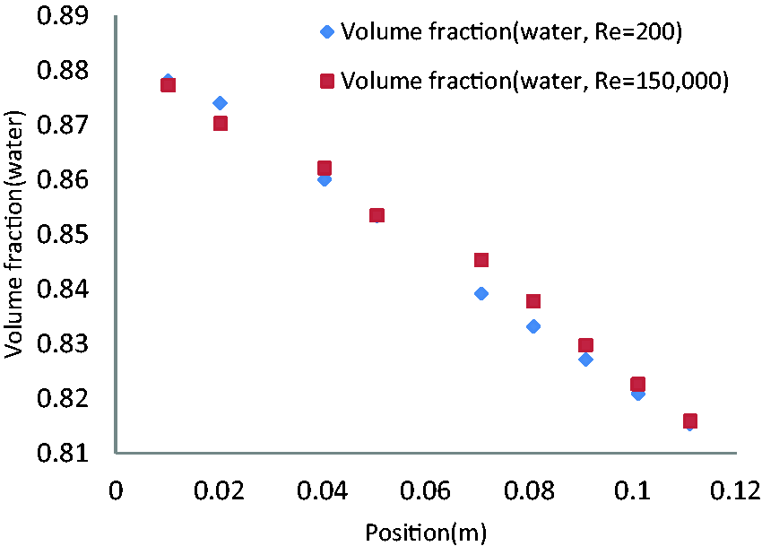
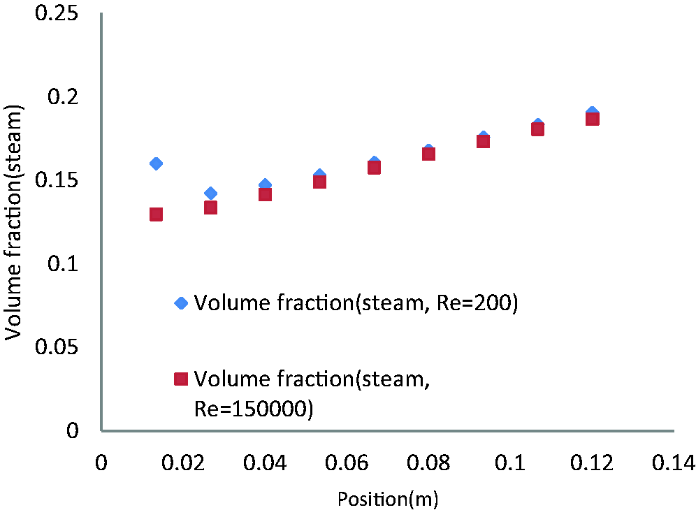
Figures 10 and 11 are the plots of the volume fraction of water versus position in a stream-wise direction and a plot of volume fraction of stream versus position in a stream-wise direction when Re = 200 and 150,000 at spacing = 6 D, respectively. The difference in the value of volume fraction is observed at all locations for the two different Reynolds numbers. The higher value of volume fraction for Re = 200 and lower value of volume fraction for Re = 150,000 are justifying the logic that more heat transfer has occurred at Re = 200 and hence more steam is formed (higher volume fraction of steam at lower Re).
Plot of volume fraction of water versus position in stream-wise direction when Re = 200 and Re = 150,000 at spacing = 6 D. Plot of volume fraction of steam versus position in stream-wise direction when Re = 200 and Re = 150,000 at spacing = 6 D.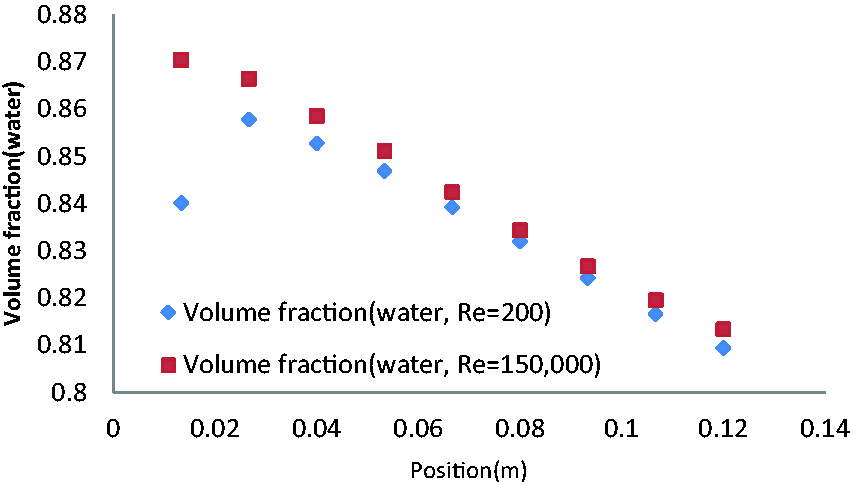
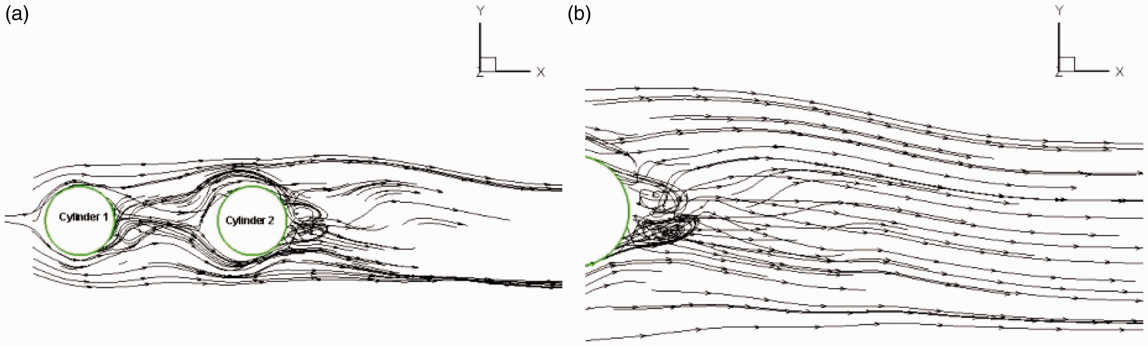
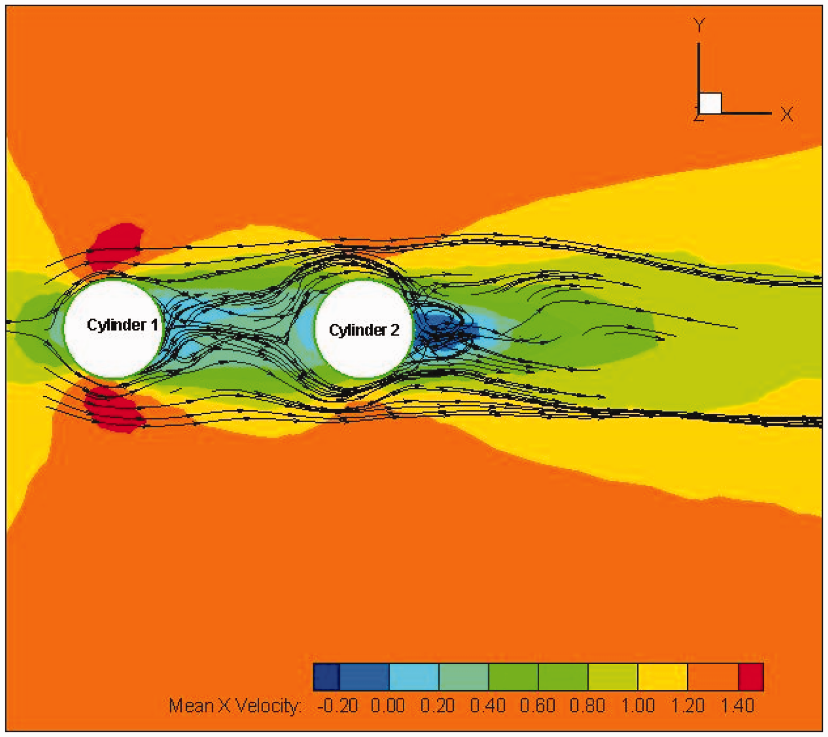
Although the focus of the study is to observe the effect of Re and spacing on the phase change phenomenon, the flow field in wake region of downstream cylinder (Cylinder 2) has also been of special interest during the study and, hence, a few plots have been presented in this paper. The wake region behind the downstream cylinder (Cylinder 2) for spacing of 1.5 D is affected by both the heating of the surface and spacing between the two cylinders. Figure 12(a) depicts streamlines over an isolated circular cylinder where the flow is 2D and Re = 200 and Figure 12(b) shows streamlines in the wake zone for an isolated circular cylinder where flow is 3D and Re = 200. The flow fields in the wake regions are different. The flow field shown in Figure 12(b) is more chaotic than that in Figure 12(a), where the region seems to be predictable and recirculation area is distinct. The study was extended to observe the flow field in the case of a two-cylinder arrangement. One case (spacing = 1.5 D) has been presented as an illustration here in this paper to understand the nature of flow filed in the wake region of downstream cylinder. The wake region gets affected by the presence of an upstream cylinder which is displayed in Figure 13. The higher value of Re (here it is 150,000) assists the flow to diminish the larger wake region that is formed in the case of lower Re (it is 200), and the 3D effect along with heat flux from the surfaces of cylinders varies the flow field variables significantly. Figure 14 is a superimposed plot that shows the distribution of mean x-velocity down in the wake region of Cylinder 2. The low negative values of velocity and the direction of stream lines confirm that the reverse flow is quite evident in the wake area.
(a) Streamlines in the wake of a single cylinder (2D and Re = 200, validation case). (b) Stream lines in the wake of a single cylinder (3D and Re = 200, validation case). (a) Stream lines over the two cylinders (spacing = 1.5 D, Re = 150,000). (b) Stream lines in the wake region of the downstream cylinder. (spacing = 1.5 D, Re = 150,000). An illustrative and superimposed plot for stream lines and contours of mean x-velocity over the two cylinders (Cylinder 1 and Cylinder 2) for spacing = 1.5 D and Re = 150,000.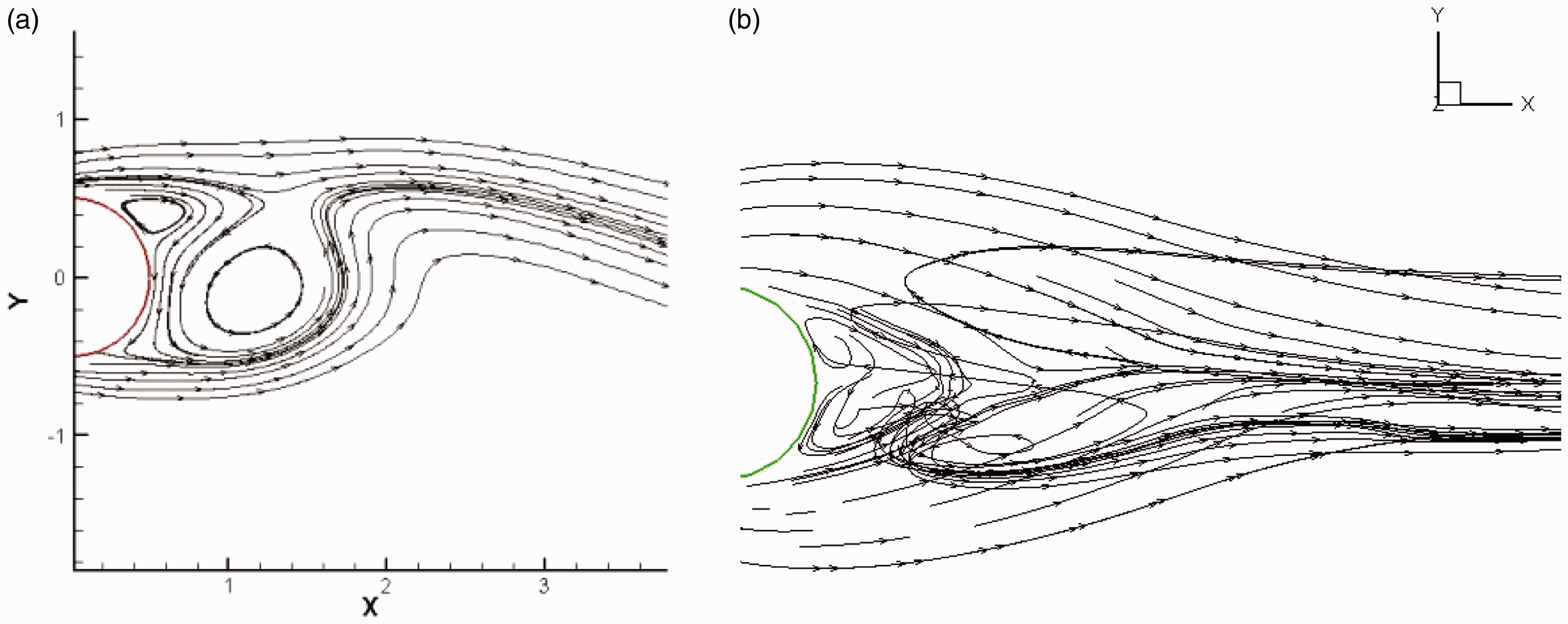
Conclusion
In this paper, the effect of phase change of water flowing across two heated circular cylinders in a tandem arrangement was studied at change in the Reynolds number. The Eulerian model was used during simulation to capture the data. First our results were verified with results mentioned in literature and then further data analysis was made for present conditions. It was observed that when the spacing is less, that is 1.5 D, the heat generated from the walls is more and hence water receives more heat from the walls. This contributes to a higher volume fraction for steam (around 54%) than that generated when the spacing is 6 D. The other finding from the solution of the above problem is that when the two cylinders are closer to each other (spacing is 1.5 D or interacting through flows) the heat transfer coefficient is almost 35% higher than that generated when the spacing is 6 D. To understand the interacting and non-interacting flows when two cylinders are kept in tandem, U+values for the 1.5 D spacing are influenced by the closeness of the two cylinders (hence flows are interacting), whereas the values of U+ remain steady (particularly linear inside the domain covering spacing and hence flows are mostly non-interacting) for 6 D spacing.
The flow filed of the wake region of the downstream cylinder is affected by the spacing between Cylinder 1 and 2, Re of the flow, 3D of the flow, and the heat flux from the Cylinder 2. The mass, momentum, and heat transfer mechanisms are unidirectional in nature and hence they transfer from Phase 1 to Phase 2.
Footnotes
Declaration of Conflicting Interests
The author(s) declared no potential conflicts of interest with respect to the research, authorship, and/or publication of this article.
Funding
The author(s) received no financial support for the research, authorship, and/or publication of this article.