
Abstract
This paper describes the numerical study of atmospheric ice accretion on rotating geometric cross sections, circular, hexagon and square, all having fins, to select an optimum geometric cross section for use as a rotating part of a newly-proposed designed icing sensor. Computational fluid dynamics-based numerical analyses were carried out in this research work to understand and analyse the atmospheric ice growth on these rotating cross sections at varying operating and geometric parameters. A comparison of accreted ice profile shapes from numerical analysis was also made with the experiments, carried out at cryospheric environment simulator (CES), Shinjo Japan. A good agreement was found between numerical and experimental results.
Introduction
Human activities in cold regions are increasingly extending, where atmospheric icing is a potential hazard which can affect human activities especially in the construction, energy, maritime and aviation-related sectors. Various structures in cold regions have been reported to damage or destroy on numerous occasions due to the added mass of accreted ice or an increase in aerodynamic interaction due to icing, leading to unacceptable dynamic movements. 1 Therefore, better knowledge of frequency and duration of icing events as well as maximum ice loads is a crucial parameter for the safe structural design and operation in cold regions.
Atmospheric icing is the term used to describe the ice accretion on structures, which occurs when freezing rain drops, and snow particles or super cooled water droplets come into contact with the exposed structural surface. 2 Atmospheric ice can be classified as: rime, glaze or mixed ice, 3 depending upon variation in density. Two processes mainly govern intensity of ice accretion on any structure: the impingement of super cooled water droplets and surface thermodynamics, which determines which portion of the impinging water freezes or on other hand melts the previously accreted ice. Most investigations related to ice accretion on structures have been performed using either ordinary wind tunnel with artificial ice templates attached to profile or icing wind tunnel, but for the last three decades or so computational fluid dynamics (CFD)-based numerical techniques have begun to play a significant role in understanding and simulating the ice growth on various structures.
Numerical study of atmospheric ice accretion on structures includes the computation of mass flux of icing particles as well as determination of the icing conditions. 4 This can be numerically simulated by means of integrated thermo-fluid dynamic models, which requires the use of multiphase analysis in order to obtain the aerodynamics flow field, the droplet behaviour, surface thermodynamics and phase change. Most developments in the numerical modelling of ice accretion have focused on aerospace sector and very few improvements have been reported in the research field of ground structural icing. Various numerical studies related to the atmospheric icing on structures can be found in the literature. The first attempts were made from the late 1970s, where researchers such as Ackley and Templeton, 5 Lozowski et al.,6–8 McComber et al.,9,10 and Smith and Barker 11 concentrated on understanding the physical ice accretion processes and developing numerical models to predict the severity of icing on structures. Later Makkonen,12,13 Finstad et al., 14 Shin et al.,15,17 Boutanios, 1 Skelton et al. 18 and Virk et al.19–21 worked on numerical modelling of the atmospheric ice accretion on different structures.
This paper describes the numerical study of atmospheric ice accretion on three different rotating geometric cross sections having fins: circular, hexagon and square. The parametric analysis are carried out by considering different operating and geometric conditions to get a better understating of ice accretion physics on each geometric cross section. The optimum geometric cross section, selected from this parametric study, is meant to be used as a rotating part of a newly proposed designed icing sensor of NUC. Figure 1 shows the computer-aided design (CAD) model of the proposed design of icing sensor with three different rotating cross sections on top (circular, square and hexagon).
Computer-aided design of proposed icing sensor, with configuration of three different rotating cross sections.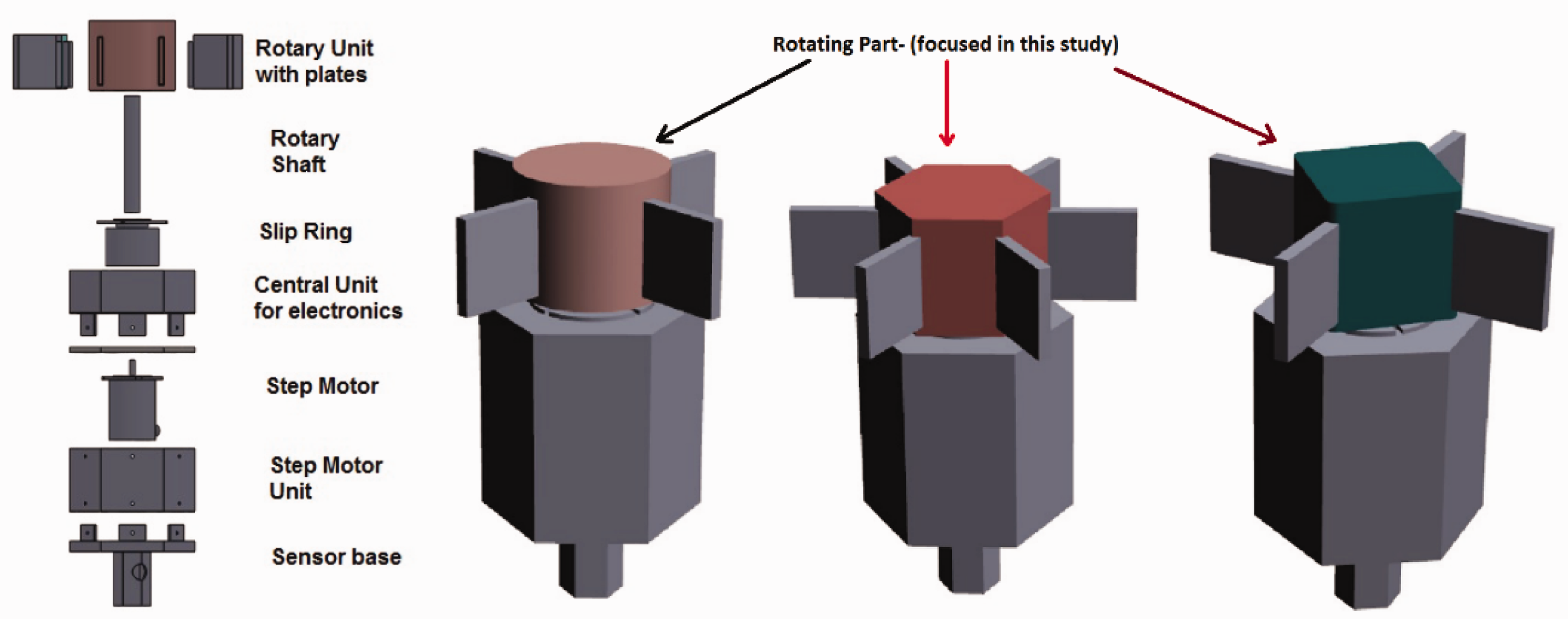
Numerical approach
Computational fluid dynamics-based numerical modelling of atmospheric ice accretion on structures mainly involves the airflow behaviour, droplet impingement and surface thermodynamics. First, it requires the airflow simulations; then super cooled water droplet behaviour is simulated to obtain the distribution of water impingement along the surface; and finally the surface thermodynamic analysis is performed to estimate the ice growth. In this research work, the numerical analysis was carried out using computational fluid dynamics-based multiphase numerical solvers, FENSAP-ICE from NTI
22
and ANSYS-FLUENT. Here, FENSAP-ICE was mainly used to simulate the airflow, droplet behaviour and resultant ice accretion, whereas ANSYS-FLUENT was used only in some cases to simulate the airflow behaviour of complex shapes, where complex turbulent behaviour is observed around the structure. In such cases, the results from ANSYS-FLUENT were coupled with the FENSAP for simulation of droplet behaviour and resultant ice accretion. Figure 2 shows the schematic overview of coupling of different processes used in these numerical simulations.
Schematic view of coupling of different processes involved in the numerical simulations.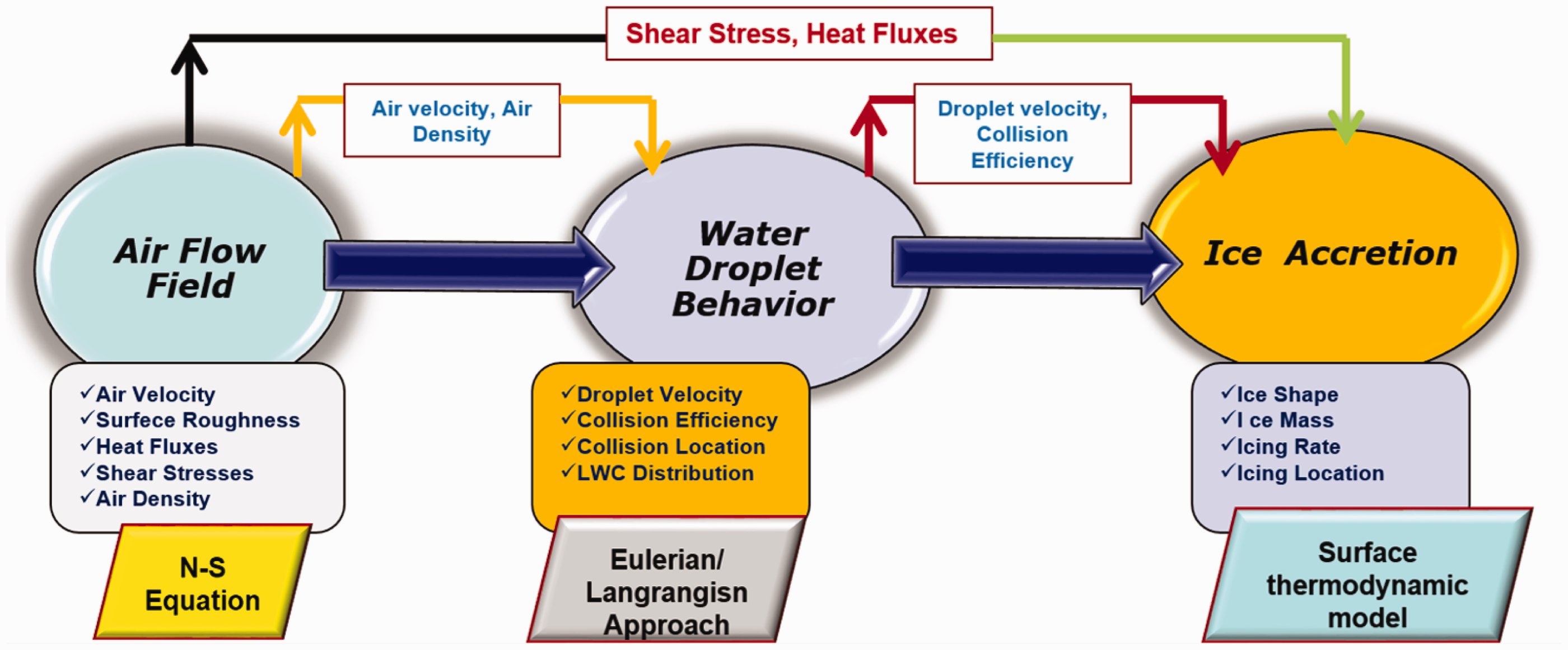
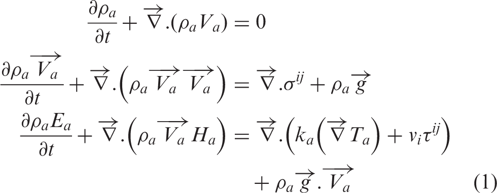
Airflow behaviour is numerically simulated by solving partial differential equations for the conservation of mass, momentum and energy. Spatial discretisation was carried out by Galerkian finite element method (FEM) and the equations were linearised by a Newton method.
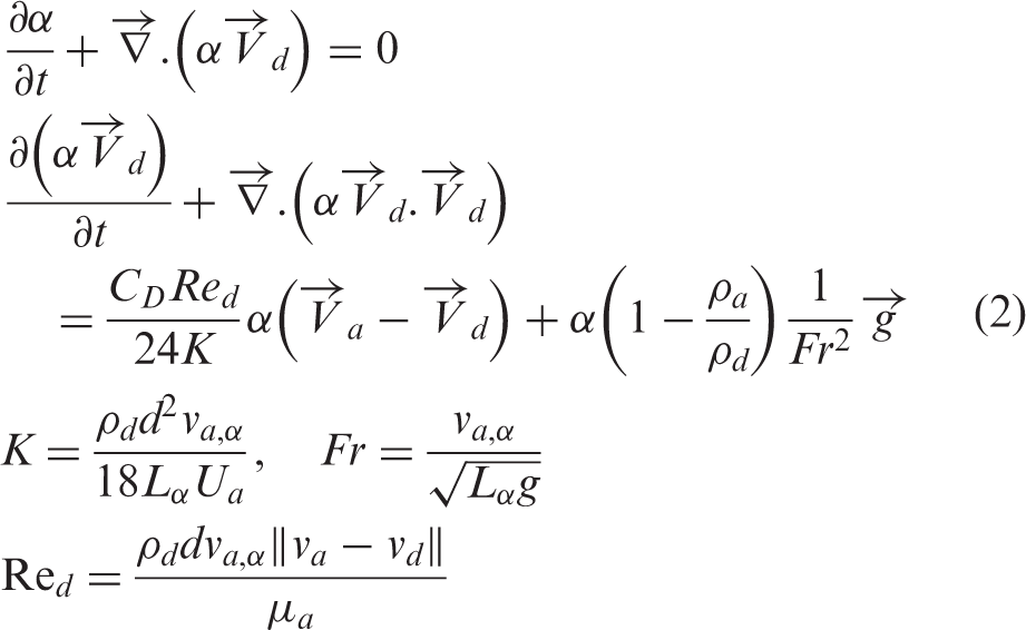


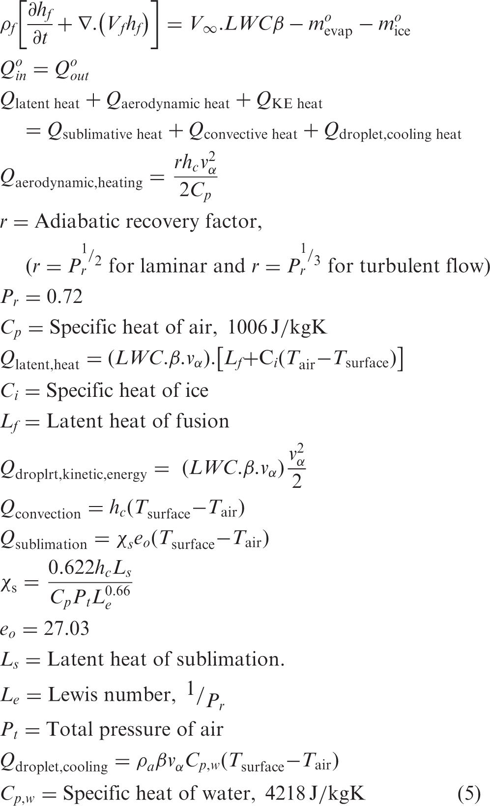
On structural surface, the contamination caused by the impinging water droplets is modelled as thin liquid film, which may run back, forced by the shear stresses created by the airflow. Based on the surface thermodynamic conditions, part of the film may freeze, evaporate or sublimate. Surface thermodynamic and icing rate are calculated by using the mass and energy conservation equations, considering the heat fluxes due to convective cooling, evaporative cooling, heat of fusion, viscous heating and kinetic heating.
24
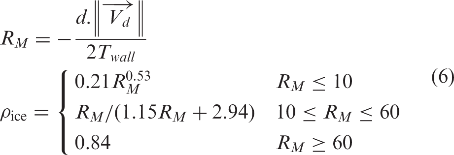
Ice density was analytically calculated by using the Jones formula, defined as
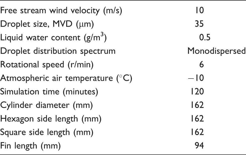
Operating conditions used for the simulations.
Results and discussion
The focus of this numerical study has been on understanding the ice growth on three different rotating geometric cross sections with fins, so that an optimum geometric cross section can be selected for rotating component of the newly-designed icing sensor the Atmospheric Icing Research Team. Parametric numerical analysis was carried out at different operating and geometric conditions to better understand the phenomena. The results obtained from numerical simulations (ice profile shape) of circular and hexagonal cross sections were also compared with the experimental results, obtained from experimental expedition of atmospheric icing research team conducted at cryospheric environment simulator (CES) Japan.
Study of geometric parameters variation
Effects of geometric shape
To study the effects of geometric shape variations on ice accretion, analysis was carried out at a wind speed of 10 m/s, MVD = 35 µm and T = −10℃ for both rotating and non-rotating conditions. Figure 3 shows the velocity streamlines across each geometric cross section. Results show a more streamlined airflow behaviour around circular cross section, compared with hexagon and square, particularly between fins. Stronger recirculating flow zone is observed in the case of hexagon and square cross section compared with circular cross section, which adversely can affect the droplet behaviour and heat fluxes involved in resultant surface thermodynamic.
Velocity streamlines across different cross sections.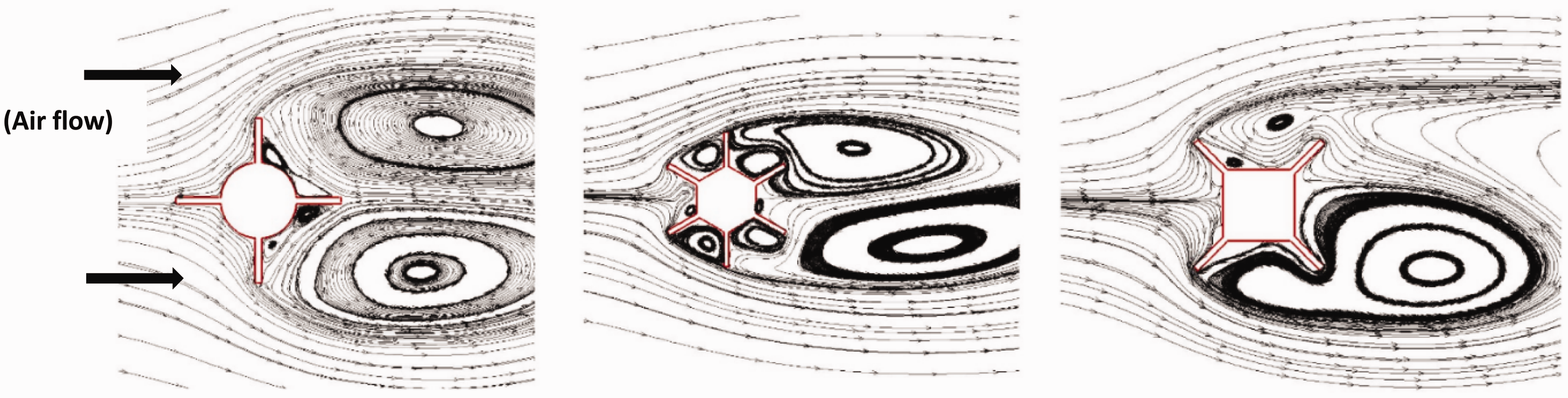
Figure 4 shows the droplet collision efficiency for each geometric cross section. The results show a smooth distribution of droplet impingement on circular cross section as compared to hexagon and square. In case of hexagon, impingement of water droplets is irregular and accumulation of run backwater is observed near the fin root section. In case of square, droplets are also irregularly colliding along the fin surface, where as in case of circle a smooth distribution of droplet impingement is observed both along the fins and the cylindrical cross section surface. The airflow and droplet behaviour are coupled with each other and any significant change in the airflow behaviour affects the resultant droplet impingement distribution and ice accretion.
Droplet collision efficiency along rotating geometric cross section, v = 10 m/s, MVD = 35 µm.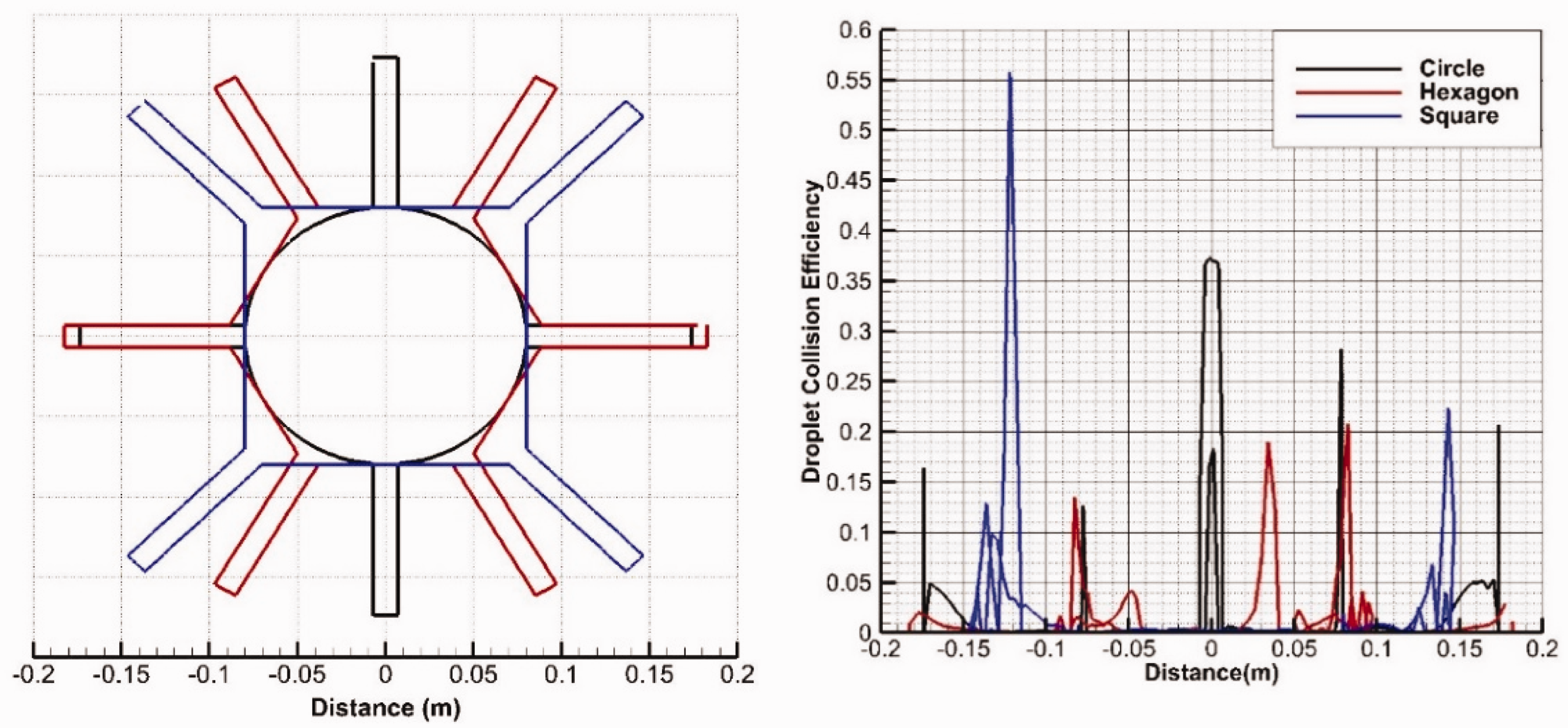
Figure 5 shows the resultant accreted ice profiles on each geometric cross section for both rotating and non-rotating conditions. The analysis shows a better distribution of ice accretion along the geometric surface in the case of rotation, compared with the non-rotating case. This is mainly because, in the case of rotation, the droplet impingement along the surface area is smoothly distributed, compared with the non-rotational case, where the droplets mainly collide with the surface area along the windward side. Such smooth distribution of ice in the case of rotation can help to minimise the dynamic instabilities due to fluid–structure interaction, while ice accretes on any structure.
Ice accretion along each geometric cross section, t = 120 min.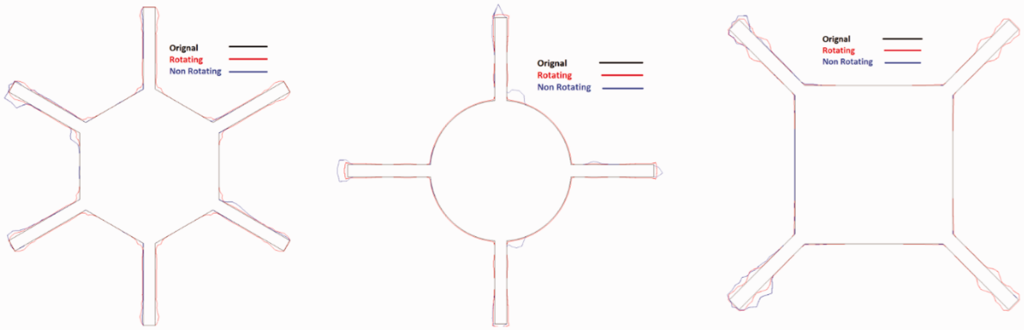
For rotating cross sections, at r/min = 6, ice accretion along the circular geometry is found to be more smooth and evenly distributed compared with hexagon and square cross sections. The process of ice accretion along any structure is generally coupled with the airflow and droplet behaviour around that structure. That is also found in this case study. Irregular ice shapes were observed along fins in case of square and hexagon cross sections due to more complex air and droplet flow behaviour between fins.
To get a better overview, further analysis was carried out to calculate the accreted ice growth and thickness for each cross section. Figure 6 shows the ice growth and thickness distribution along each cross section and the results clearly highlight the uneven distribution of ice loads along the hexagon and square cross sections. Especially in the case of square cross section, the ice load distribution is more uneven along the fins, whereas in case of hexagon cross section, more water run back along the fins is observed, which leads to accumulation of more ice near the fin root section.
Ice growth and thickness distribution along each rotating geometric cross section for t = 120 min.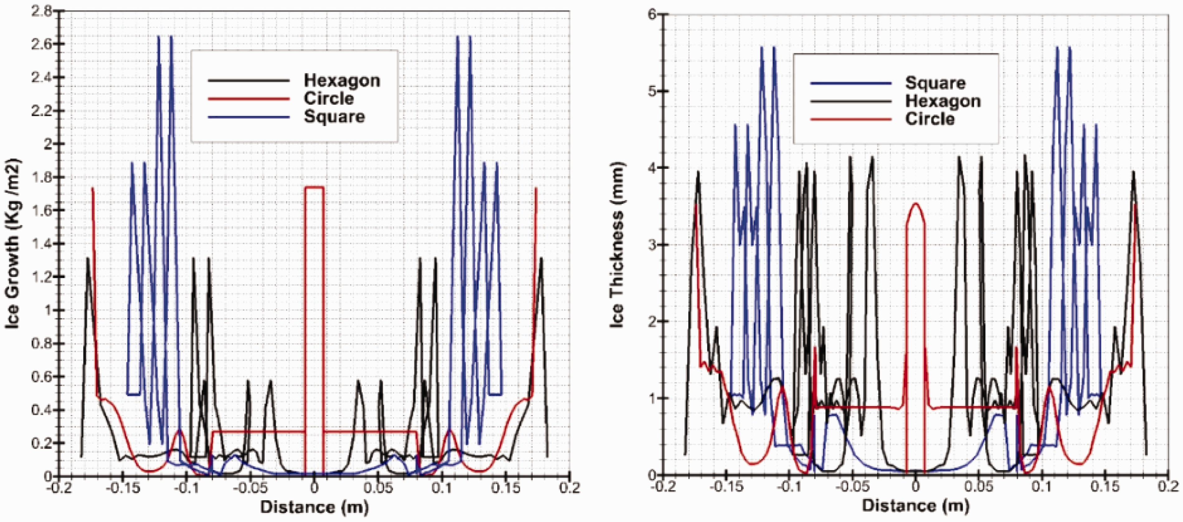
To further analyse the ice growth, numerical analysis on circular and hexagonal cross sections was extended for a total simulation time of 5 h (300 min). Figure 7 shows that ice load distribution along circular cross section stays smooth even for longer intervals of time, whereas in the case of hexagon cross section the accumulated ice shapes become more irregular for longer durations of time.
Ice accretion on circular and hexagonal cross sections for different time intervals.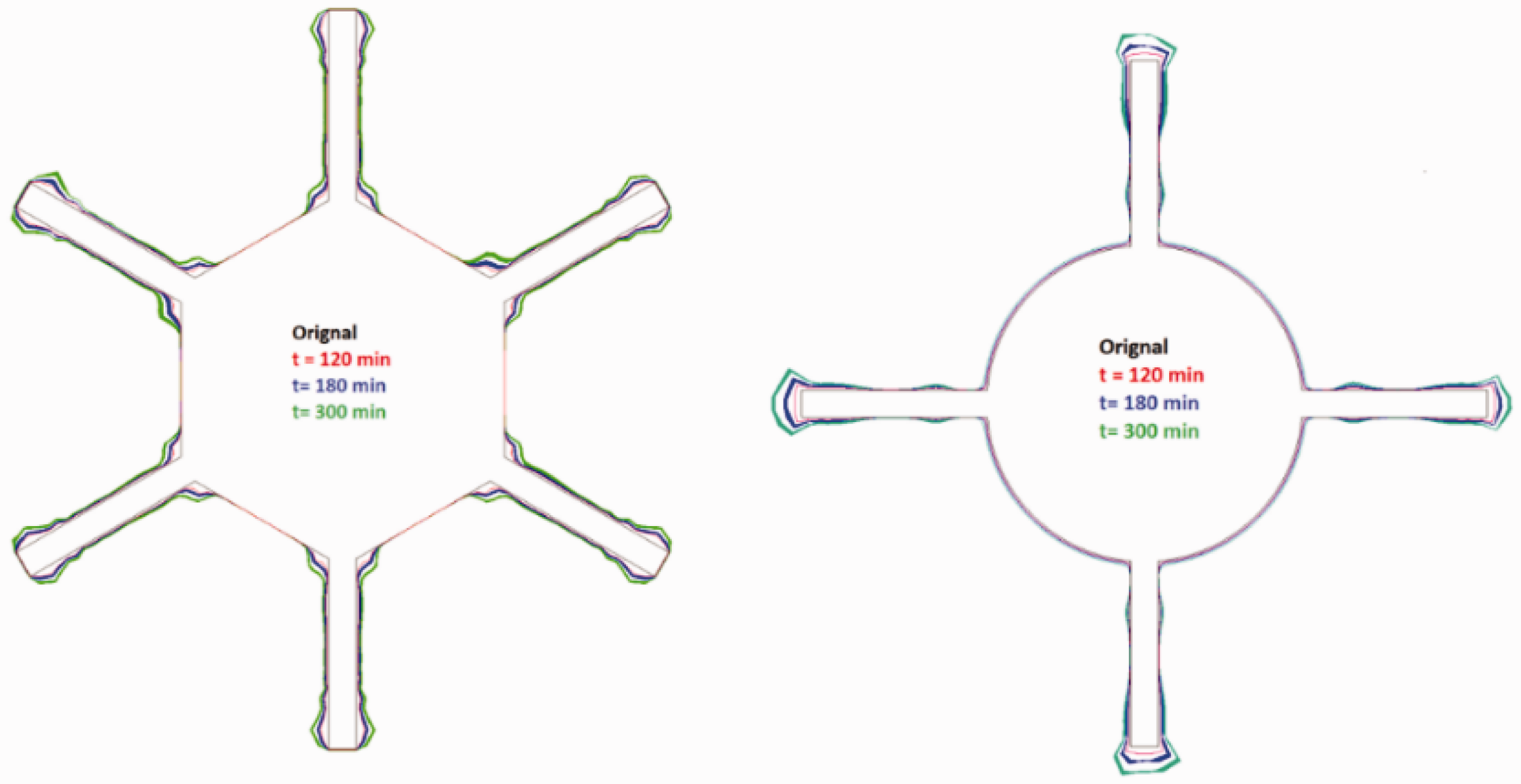
The numerically simulated ice growth on circular and hexagonal shapes were also compared with the experiments carried out at cryospheric environment simulator (CES) Shinjo, Japan. Data for the droplet size and liquid water content during experiments were not available at CES, therefore exact comparison of ice load and thickness was not possible and only the accreted ice shapes were compared with each other. Overall, the accreted ice shapes on circular and hexagonal cross sections using numerical simulation were found to be in reasonably good agreement with the experimental results. Figure 8 shows the accreted ice shapes on circular and hexagonal cross section for numerical and experimental analysis for a total duration of 3 h.
Comparison of accreted ice profile shapes from numerical and experimental analysis for t = 180 min.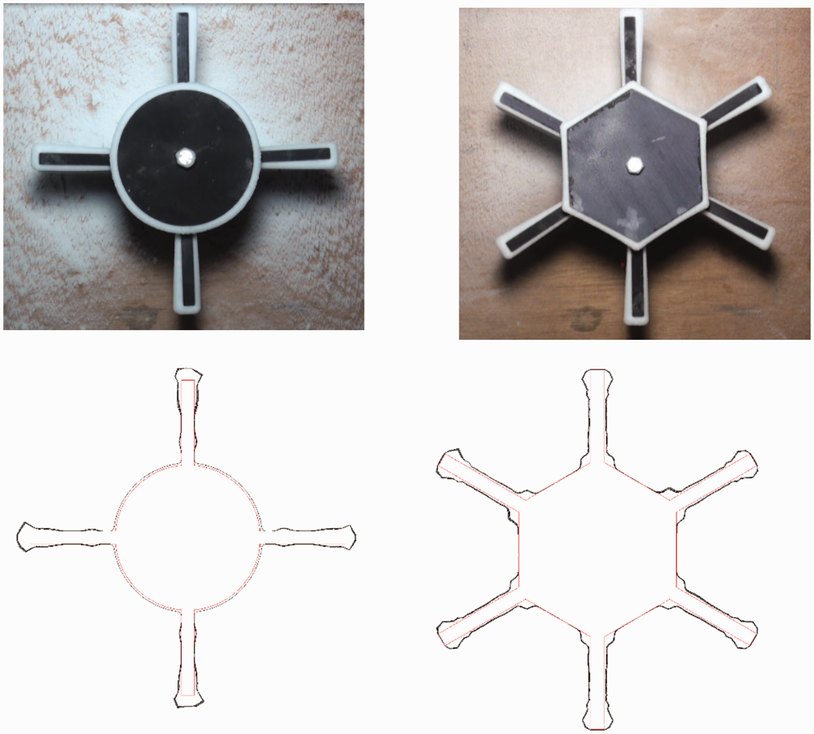
Effect of fin length
To understand the effects of fin length on resultant ice growth along rotating geometries, analyses were carried out considering circular cross section at operating conditions specified in Table 1. Two different sizes of fin length (47 and 94 mm) were used for this study. Results show a considerable change in the ice growth with fin size variation. Decrease in fin length is considerably changing the flow behaviour along the fins, which is resulting in development of stronger flow recirculation zones along the fin section. Figure 9 shows a comparison of velocity streamlines for two different fin size cases.
Velocity streamlines for circular cross sections having two different fin sizes (94 and 47 mm).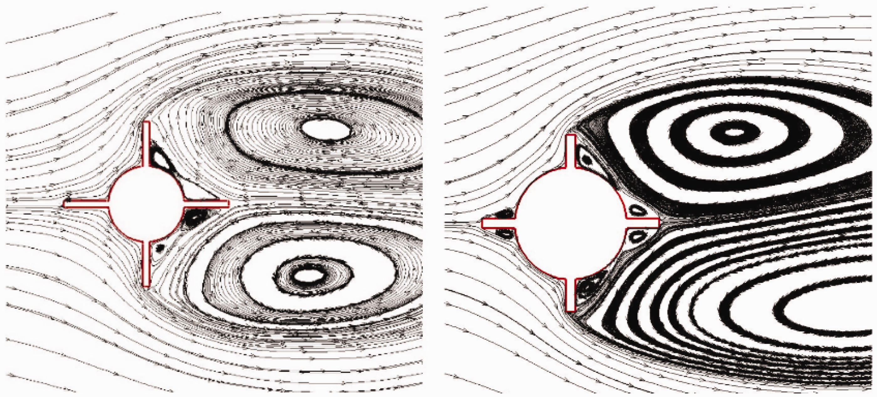
The change in flow behaviour and development of flow circulation zones along the fins by reducing its size, also affect the droplet behaviour and impingement along surface, which leads to a change in resultant ice accretion. Figure 10 shows the shape of accreted ice and resultant ice thickness for both cases. Analyses show an increase in ice growth particularly along tip sections of fin in case of reducing its length.
Effect of fin size on ice accretion along the circular cross section.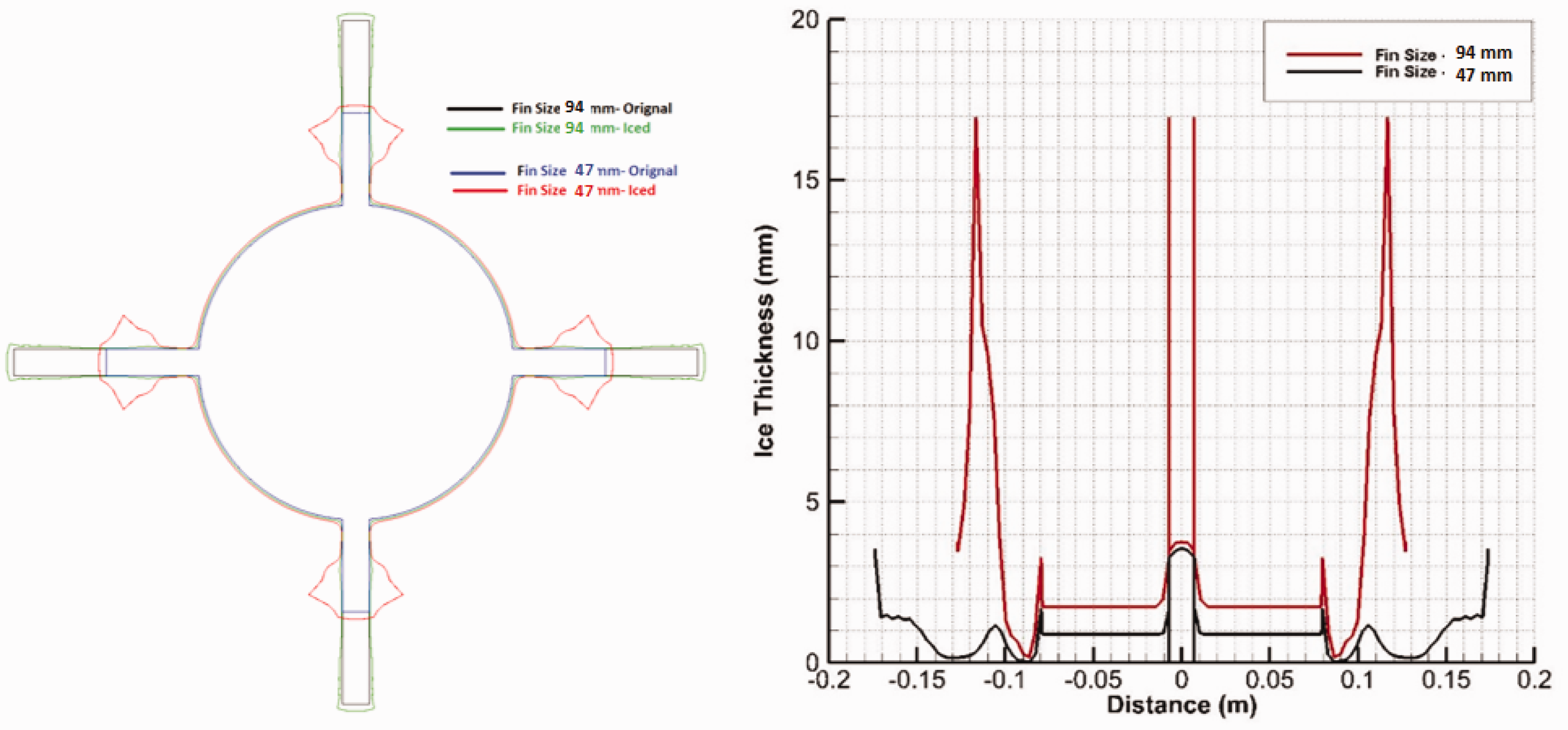
Effect of geometric surface roughness
Different geometric surface roughness distributions can result in different ice shapes, due to their influence on water runback characteristics and the resultant ice coverage. 26 Along different areas of real iced surface, the roughness should behave as different patterns or texture, according to the geometric configuration and atmospheric conditions. The surface roughness is known to make an important contribution to the convective heat transfer and surface water mass flow.
The effect of surface roughness on resultant ice growth along the circular cross section has been investigated by imposing two different sand grain roughnesses (0.5 and 2 mm). Figure 11 shows the accumulated ice shapes and ice thickness for two different sand grain roughness along the circular cross section. Analysis shows a considerable change in resultant ice growth particularly along fin sections with the increase in surface roughness to 2 mm. Increase in surface roughness increases the possibilities of development of beads along the surface, which possibly leads to an increase in ice accretion. This change in ice accretion is mainly due to change in the tangential and normal shear stress distributions along the surface due to the airflow at the air–water interface that plays a crucial role not only on the convective heat transfer rate at the disturbed air–water interface, but also on the height of the accumulated iced surface roughness.
Effect of surface roughness on ice accretion along the circular cross section.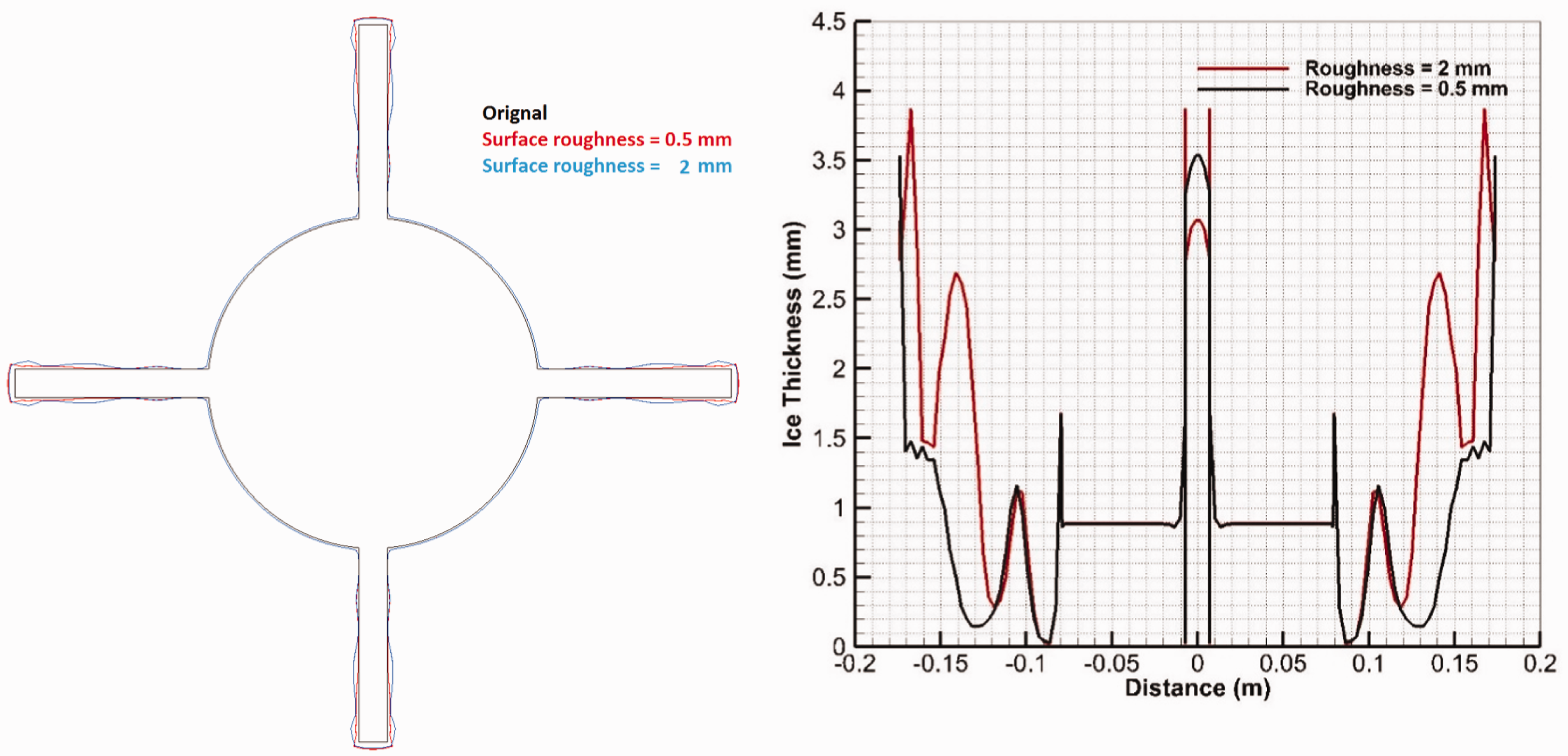
Study of operating parameters variations
Effects of atmospheric temperature
To study the effects of atmospheric temperature variations on ice accretion, analyses were carried out for both dry and wet ice conditions (T = −3 and −10℃), for circular and hexagonal cross sections. Figure 12 shows the accreted ice shapes and thickness for both geometric cross sections. Results show a significant change in accreted ice shapes for the hexagon with the increase in temperatures, compared with the circular cross sections. At −3℃ (for wet ice conditions), more irregular ice shapes were observed near the fin tip sections, but resultant ice growth was less for both geometric cross sections, whereas for the dry rime ice conditions, more regular ice shapes were found with ice growth. The change in accreted ice shape by the variation of atmospheric temperature is somehow also coupled with the flow behaviour, as in the case of hexagon cross section, more disturbed airflow and droplet behaviour is observed, which possibly effects the resultant heat fluxes (aerodynamic and impinging droplet kinetic energy) and shear stress distributions along the surface that changes the ice growth. The ice growth and thickness in case of hexagon cross section is found to be more irregular at wet ice conditions, compared with the circular cross section.
Ice accretion at different atmospheric temperatures for t = 120 min.
Effect of wind velocity
To study the effect of wind velocity variations on ice accretion, analyses were carried out at two different wind velocities (10 and 25 m/s) for rotating circular and hexagonal cross sections. Figure 13 shows the accreted ice shapes and growth for both geometries. The analysis shows a significant change in ice growth with the increase of wind velocity for both geometries. An increase in wind velocity increases the possibility of droplet collision with the geometric surface, which results in increase of ice growth. The analysis also shows that in case of hexagon cross section, the ice shapes get more irregular along the fins at high wind speed, which is mainly due to more irregular flow behaviour along the fins, as discussed above, and also increase in the heat flux due to convection, aerodynamic heating and changes in droplet impingement kinetic energy. Results show that accreted ice shapes in case of circular cross sections remains streamlined compared with hexagonal cross section even at high wind speeds.
Effect of wind velocity variation on ice accretion, t = 120 minutes and T = −10℃.
Effect of droplets size
To study the effect of water droplet size variation on resultant ice accretion, numerical analyses were carried out for two different droplet sizes (MVD = 35 and 70 µm), at atmospheric air temperature of −10℃ and wind speed of 10 m/s. Figure 14 shows the ice growth for two different droplet sizes along the circular cross section. Analysis shows that change in the droplet size effects the ice accretion, as increasing the droplet size increases the possibility of droplet impingement. The main reason for this can also be explained by the fact that larger diameter droplets have larger inertia compared with smaller droplets. Therefore, the movement of larger droplets is less affected by the airflow and more of the droplets collide with the surface, which results in increase of the ice growth.
Effect of droplet size variation on ice accretion. Effect of rotational speed variation on ice accretion.
Effect of rotational speed
To study the effect of geometric rotational speed, numerical analyses carried out for two different rotational speeds (r/min = 6 and 30) of a circular cross section, at atmospheric air temperature of −10℃ and wind speed of 10 m/s. Analysis shows that increase in r/min leads to an increase in ice growth, particularly along the fin sections. This is mainly because increase in the r/min increases the tangential component of flow velocity, which leads to a change in the droplet behaviour and water run back, as results show a development of ice hump near the fin root section.
Conclusion
A CFD-based numerical study has been presented in this paper to understand and analyse the rate and shape of atmospheric ice accretion on three different rotating geometric cross sections having fins. Numerical analyses provided a base to better understand the ice accretion process on each geometric cross section at different operating and geometric conditions. Results showed that overall the ice accretion on circular cross section is smoother and more regular compared with the square and hexagonal cross sections due to more streamlined airflow and droplet behaviour. The result also shows that a fin size of 94 mm at an r/min of 6 with a circular rotating geometry displays a better ice accretion profile shape compared with the hexagonal and square cross sections. The ice accretion profile for the hexagon cross section with six fins was nevertheless better than the square cross section with four fins. This study lays a foundation to select an optimum geometric configuration for rotating component of the newly-designed icing sensor.
Footnotes
Declaration of Conflicting Interests
The author(s) declared no potential conflicts of interest with respect to the research, authorship, and/or publication of this article.
Funding
The author(s) disclosed receipt of the following financial support for the research, authorship, and/or publication of this article: The work reported in this paper was partially funded by the Research Council of Norway, project no. 195153 and WindCoE (Nordic Wind Energy Centre) project funded within Interreg IVA Botnia-Atlantica, as part of European Territorial Cooperation (ETC).