
Abstract
In this paper the flight dynamics of a 33-gram twin-cyclocopter is analyzed via deriving a Linear Time Invariant (LTI) dynamics model from flight test data. The twin-cyclocopter is a novel micro air vehicle that uses two co-rotating cycloidal rotors to generate thrust and a coaxial nose rotor to counteract the reaction torque and provide additional thrust. During flight tests, perturbation maneuvers were performed about the hovering state to excite different modes and a 3D motion capture system collected attitude and position data. The data was used to extract a bare airframe LTI model linearized about the hovering state using time-domain system identification techniques. The model demonstrated that the roll and yaw modes are gyroscopically coupled with stable high-frequency and low-frequency modes. Comparing the two different yaw control methods: thrust vectoring of the cycloidal rotors and differential torque of the coaxial nose rotor, the former was more effective.
Introduction
It is no secret that small, capable, flying vehicles are growing more popular and more essential to many industries. This is largely because of the rapid developments in electronics and software that greatly improved the performance of these systems thereby transforming them from hobby toys to commercial and even military equipment. This ever-growing field is dominated by one particular type of Micro Air Vehicle (MAV): the multi-copter. Whether it is a quad-, hex-, octo-, or deca-copter the trend is to unwaveringly add or reduce the number of small conventional rotors as needs dictate with seemingly no upper limit (Figure 1).
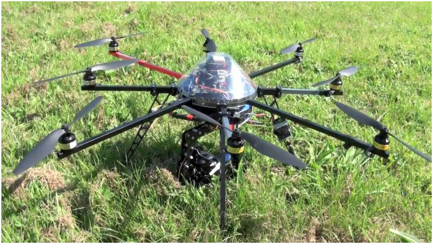
Multicopter drone design utilizing eight rotors.
All this in an effort to produce ever smaller flying craft that can be portable and functional in a world that is constantly in motion. Reduced size enhances portability and expands the profile of potential missions. Lugging around suitcases of equipment is less than desirable for everyone, the average drone enthusiast and military operator alike. Given the choice between a smaller and larger MAV that both serve the same function, more often than not the smaller one will be selected. Furthermore, a reduced footprint could broaden the range of applications for MAVs in both civilian and military sectors. A smaller, lightweight vehicle can be flown indoors where a larger UAV might not be able to maneuver and it can do so with more relative safety to the people in its vicinity. There is also the opportunity for enhanced clandestine operation when avoiding detection is paramount.
Regardless of the configuration, as traditional MAVs are scaled down they have to contend with the reduced aerodynamic performance of rotors and wings, which limits their flight envelope. The primary aerodynamic limitation of conventional rotors/propellers used in MAVs is their reduced efficiencies at low Reynolds numbers (10,000–50,000), in particular, low values of maximum figure of merit (around 0.65).1,2 The reduced aerodynamic performance is caused by large profile drag associated with thick boundary layer formations on the blades, large induced losses, and higher rotational and turbulent losses in the downstream wake of the rotating blades.3,4 MAVs are also highly susceptible to disturbances such as wind gusts because of their lower inertia. As an aerial vehicle is scaled down it’s rotational inertia are reduced by
It is for these reasons that significant motivation exists to investigate further into unconventional thrust generation and control techniques, including various out-of-the-box propulsion concepts such as flapping wings and cycloidal rotors (or cyclorotors). The focus of this paper is application of the cyclorotor, which is a non-traditional concept that consists of several blades that rotate about a horizontal axis with the blade span parallel to the axis of rotation.
Figure 2 illustrates how the pitch angle of each blade is varied periodically as it moves around the azimuth of the cyclorotor such that the blade is at a positive geometric angle of attack both at the top and bottom halves of its circular trajectory. The magnitude and direction of the net thrust vector of the cyclorotor can be changed by varying the amplitude and phase of the cyclic blade pitch. Since the thrust vector of a cyclorotor can be instantaneously set to any direction perpendicular to the rotational axis, the concept may also have better maneuverability compared to conventional rotor based MAVs, which makes it ideal for highly constrained indoor operations and gusty outdoor environments.
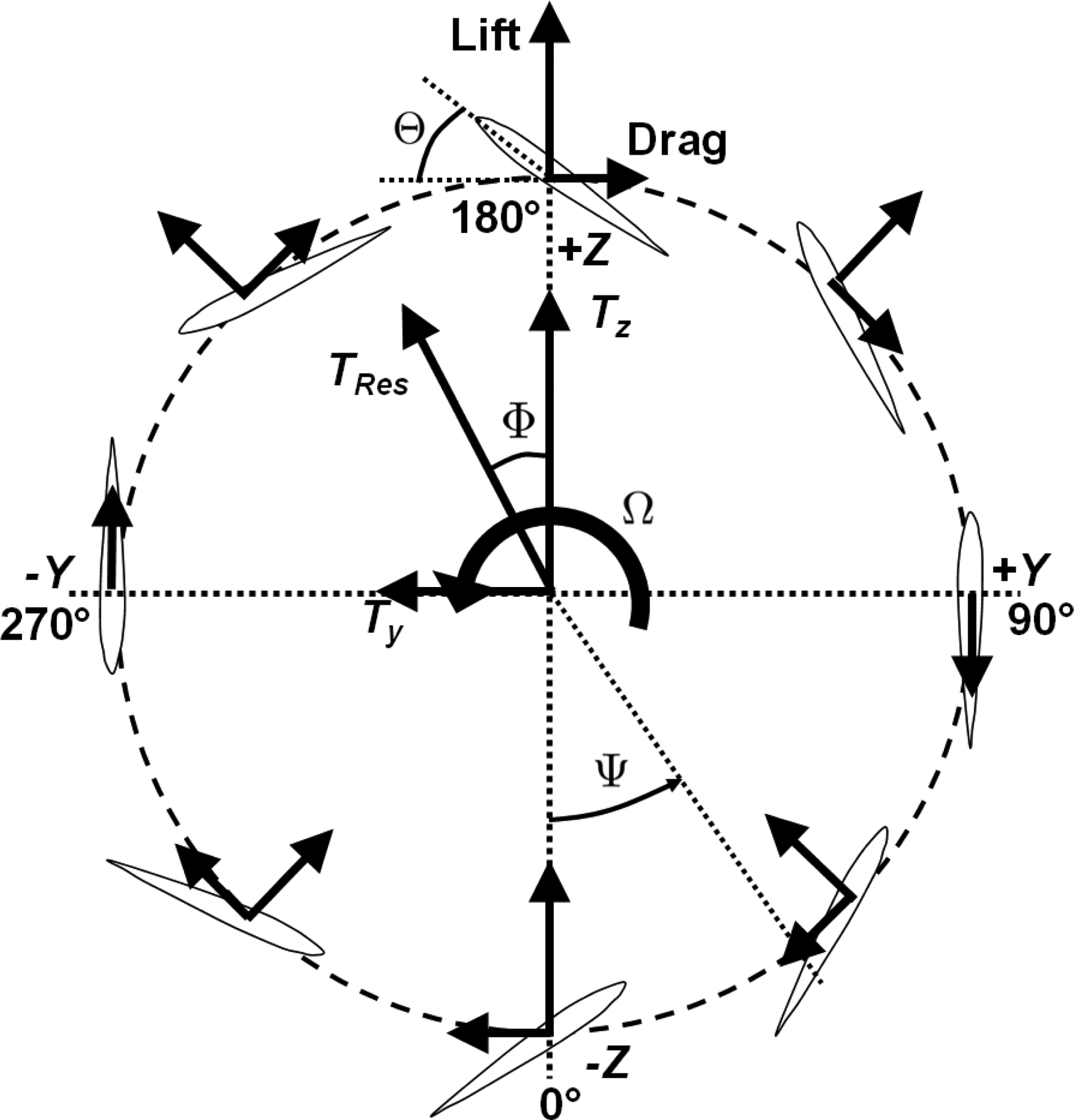
Blade kinematics and forces on a cyclorotor.
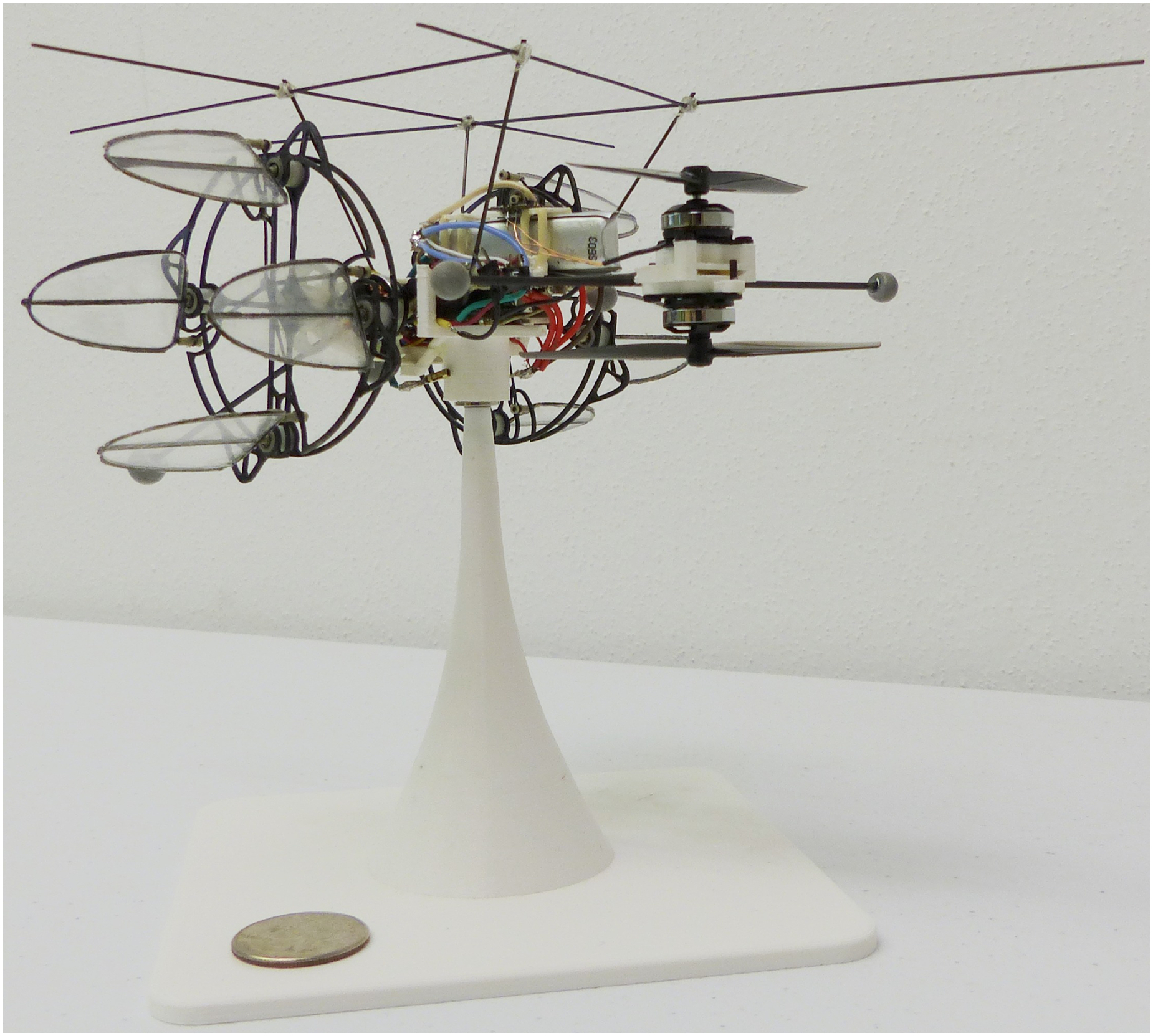
Cyclorotor-based platforms have been built at sizes ranging from 30 grams to hundreds of kilograms for mobility in both aerial and aquatic environments. Research into the use of cyclorotors for MAVs has demonstrated their superior performance in comparison to conventional rotors. For example, extensive experimental studies 5 have shown that a cyclorotor may be more aerodynamically efficient than a conventional rotor of the same scale. This is in part due to the fact that all the spanwise elements of the blade operate at the same aerodynamic conditions, allowing each of the blade elements to be set at its optimum condition. Previous aerodynamic studies performed by the author cyclorotors6–12 have included detailed performance measurements and flow-field analysis using Particle Image Velocimetry (PIV). These were done in an effort to understand the force production and optimize the aerodynamic efficiency of MAV-scale cyclorotors. Additionally, an aeroelastic model to predict the hover performance of a cyclorotor has been developed and validated. 13 The cyclorotor used for the research presented in this paper is the smallest of the referenced cyclorotors (as well as the smallest one built to date) and has a unique design (Figure 3).

Micro Twin-Cyclocopter with coaxial nose rotors.
In order to scale down the cyclorotor concept, a rigorous parametric study was conducted to optimize performance at the desired operating range. PIV-based flow field measurements were also performed to understand the complex 3-dimensional flow that is unique to the scaled down design. 12 These optimized cyclorotors have been incorporated into a twin-cyclocopter platform that has demonstrated stable, hovering flight. 14 The current 33-gram vehicle is one of a family of cyclocopter MAVs developed by the authors that utilizes this specialized cyclorotor (Figure 4).

Hover-capable cyclocopters developed by the authors.
While system identification has been done previously on a larger 550-gram cyclocopter to obtain a Linearized Time Invariant (LTI) dynamics model, 15 this new vehicle is significantly different due to its size and design and, therefore, warrants a thorough investigation. Because of the significantly lower mass and rotational inertia, this 33-gram cyclocopter exhibits faster dynamics, a greater degree of gyroscopic coupling, and unexpected responses to benign commands. As such, a dynamical model could reveal much about this type of aircraft. The LTI model can be used to quantify the flight performance of the micro-cyclocopter in order to understand how the inherent dynamics change when the vehicle is scaled down and also to compare the cyclocopter MAV to conventional rotary-wing MAVs of similar scales. Additionally, such a model can be used to develop improved model-based control strategies, conduct simulations, and extract maneuverability and disturbance rejection metrics. 15 This paper details the process used to extract a bare airframe model through systematic flight testing followed by a discussion of the results. A bare airframe model captures the response of the vehicle to natural physics and control actuator effectiveness agnostic of any control system implementation or stability augmentation. A brief description of the design and development of the vehicle is provided prior to the discussion of the system identification experiment.
Vehicle design and development
On this small-scale device several design choices were made to take advantage of its diminutive nature. Inspired by tiny fliers found in nature, these cyclorotors were crafted with cantilevered blades that somewhat resemble insect wings. Qualities that emulate insects include the low aspect ratio elliptical planform shape and flat-plate airfoil that has higher performance at these low Reynolds numbers (
The blades are secured to the endplate structure via a Delrin® spacer that has two micro-bearings and a PEEK bushing (Figure 5). Linkages made via a similar mold-layup process are connected to the pitch horn with additional PEEK (polyether ether keytone) bushings and are part of a 4-bar linkage mechanism housed between the two

Micro-cyclorotor with components labelled.
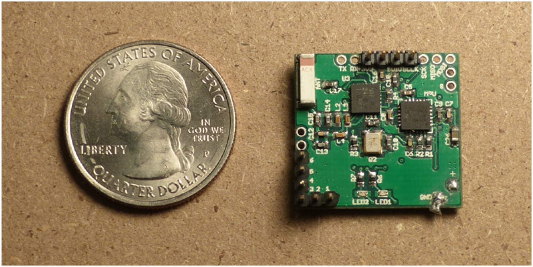
Custom built 1.3-gram kinematic autopilot with U.S. quarter for size comparison.
Coaxial nose rotor
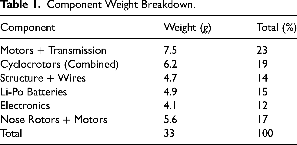
Previous studies18,19 have characterized the performance and flowfield of the small cyclorotors used on these vehicles as well as validated the hover performance of the 29-gram twin-cyclocopter configuration shown in Figure 4. All of the previous twin-cyclocopter vehicles had a single nose rotor. Reference 20 also outlines efforts to capture the flight dynamics of that single nose rotor twin-cyclocopter. That study showed a high-degree of coupling partially because of the gyroscopic moments. The unbalanced yaw torque and angular momentum of the single nose rotor meant that any rolling or pitching motion produced an off-axis moment that made the dynamics highly coupled and non-linear, which resulted in poor handling qualities for the vehicle. In response to this, a second counter-rotating rotor was added to balance the torque and angular momentum generated about the vertical axis of the vehicle. This ameliorated the aforementioned gyroscopic couplings, fully isolating the pitching motion from the roll and yaw directions. Moreover, now it was not needed to counteract the unbalanced torque from the single nose rotor by canting the thrust vectors of the cyclorotors, which helped reduce the impact of variations in cyclorotor rpm on yaw. Another practical benefit resulting from the reduction in coupling is the fact that during flight testing a stable hover trim can be achieved significantly faster because cyclorotor thrust vectors can be trimmed independently of the nose proprellers and pitch trim. To date, this is the only twin-cyclocopter built with coaxial nose rotors, prompting this study into its flight dynamics. A weight breakdown of this 33-gram vehicle is shown in Table 1.
Component Weight Breakdown.
Flight tests
The first step to prepare the vehicle for system identification is to trim it around the state of interest, which in this case is hover. The present twin-cyclorotor configuration has 6 controls: four motor speeds and two cyclorotor thrust directions controlled by the servo actuators, making this an over-actuated system. There are many potential advantages to this (e.g., maneuverability and disturbance rejection) that have been investigated in Refs. 15,20.
Attitude control
In order to understand how the vehicle is controlled and trimmed a short summary of the attitude control strategy is presented. The magnitude and direction of forces and moments are controlled through altering motor speeds and thrust-vectoring servos in specific combinations to control roll, pitch, and yaw. The body axes are defined as shown in Figure 7 where the coaxial rotor is considered the front of the aircraft.
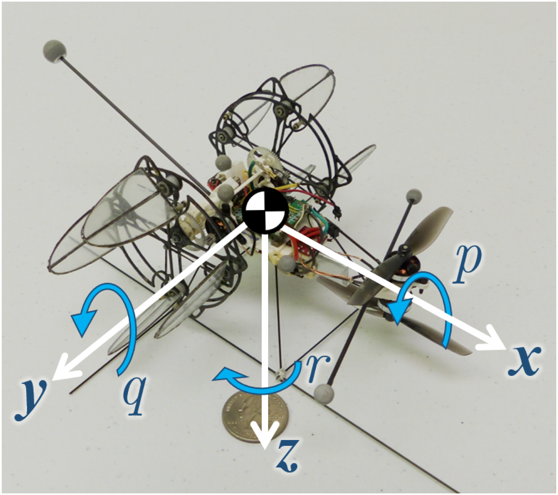
Micro-cyclocopter with body axis frame shown and corresponding positive body angular rates.

A positive roll moment generated by changing thrust of the cyclorotors.

A positive pitch moment generated by increasing nose rotor thrust.

A positive yaw moment generated by vectoring cyclorotor thrust.

A positive yaw moment generated by offsetting nose rotor thrust to generate torque.
Trimming
Unfortunately, due to over-actuation, the vehicle has multiple trim states that result in level flight; however, only one eliminates constant drift as well as controller-induced couplings. Finding the proper trim state can be a challenging task. Specifically, in the case of the micro-cyclorotor, it is not easy to assess small variations in the direction of the net thrust vector. This is the primary reason why the present configuration uses a counter-rotating coaxial rotor in the front instead of a single rotor like the 29-gram vehicle in Figure 4. By eliminating the nose rotor yaw torque there is no need to differentially vector the cyclorotor thrust to counteract it, which means that trimming for hover demands perfectly vertical thrust vectors (
Micro-cyclocopter mounted upside-down on single axis yaw stand.
Feedback
Once the vehicle was successfully trimmed for hovering flight, feedback gains were introduced in order to provide an additional level of stability augmentation necessary beyond a human pilot’s capability in order to automatically stabilize the attitude of the vehicle. These strategies were implemented on a custom-designed flight control board that used an STM32F4 micro-processor with gyros and accelerometers to sense body axis rotational rates and accelerations. These data were used in a cascaded loop structure as shown in Figure 13. Roll and pitch were stabilized by experimentally tuned PPID control loops (PID: Proportional-Integral-Derivative) that stabilized the vehicle about a desired angle. For the outer P loop, commands from the transmitter were converted to a desired body angle by a linear equation. Error between the commanded angle and the measured angle was then multiplied by the outer P gain to produce a desired body angular rate, which became the input for the inner PID loop. Because heading angle was not measured, no outer P loop was implemented for yaw and the associated transmitter commands were converted to a desired body angular rate as the input for a PID loop.

Feedback loop architecture for normal test flight operations.
Pilot inputs and trims are sent through a base station that concurrently collects vehicle telemetry from the flight, while also performing several other functions. Hover being the desired state for this experiment, effort was focused on reducing constant drift and yaw. All flight tests were conducted in a specially arranged space measuring 15
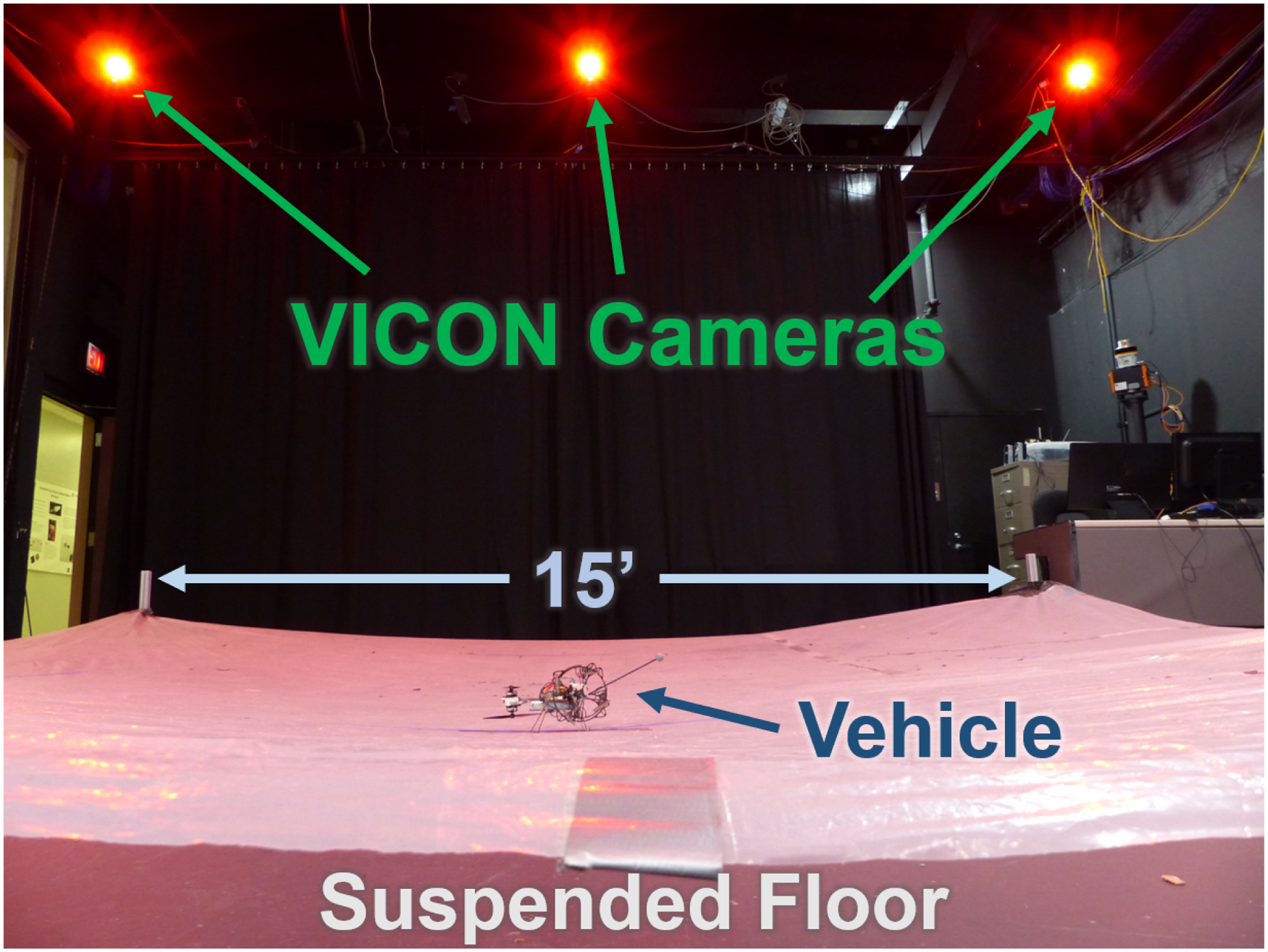
Flight space with suspended floor and Vicon cameras.
Flight dynamics identification
Having achieved stable, hovering flight, preparations had to be made for the collection of data that would allow the extraction of a bare airframe LTI model. Linear system identification involves perturbing the vehicle from a trim state (hover in this case), recording the control input and system response, and deriving linearized equations of motion to model the system response with the vehicle states. Reference 22 explains the process of linearizing the non-linear aircraft equations of motion about a desired equilibrium point using Taylor Series expansion. The result is the familiar linear state space equation:


The values in
Data collection
A modified loop structure is used to control the cyclocopter during data collection that allows for the derivation of a model that is independent of controller implementation (Figure 15). This loop more closely comports with the assumptions of linear analysis, particularly the assumption that the vehicle is always driven back to a trim point. As such, the control inputs in

Feedback loop architecture for system identification experiments and data collection.
The perturbations to excite the various modes of the system were provided by the pilot rather than generated by a computer because it was imperative to prevent the craft from going unstable and human inputs tend to contain a broader spectral character.
26
Various input methods were compared: doublets of various periods, frequency sweeps, and impulses. No benefit was observed in data quality or model accuracy by using more complicated inputs so simple impulses were the preferred method of excitation. A sample of flight test data can be seen in Figures 16 to 19. The data was filtered using a

Representative flight test data for longitudinal perturbation experiment.
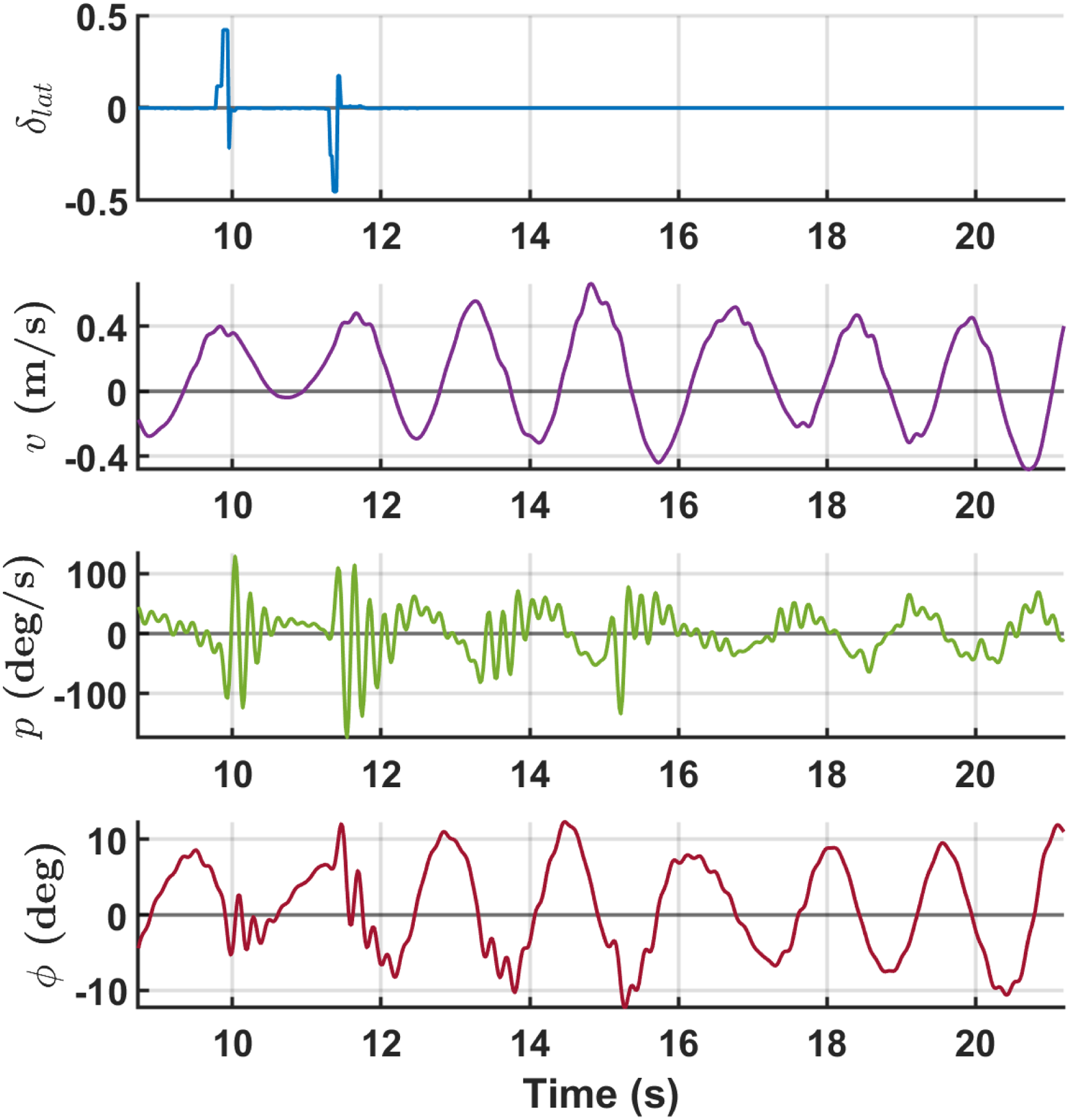
Representative flight test data for lateral perturbation experiment.

Representative flight test data for directional perturbation experiment.

Representative flight test data for heave perturbation experiment.
Within these, a periodic motion in roll and yaw can be seen that is not associated with any control input (Figure 17). This motion is part of the open-loop dynamics and develops naturally from a stationary hover. It was noted in flight testing that an increase in throttle damped this mode out and eliminated it during vertical ascent. Conversely, a descent seemed to induce or exacerbate this motion.
Linear model
Over 50 sets of similar data were collected in this manner and analyzed using the SIDPAC® code. This code linearly relates the vector of measured regressors with their derivatives using a least squares fit. To help the researcher select meaningful and well-correlated parameters in the matrix, SIDPAC® displays two primary metrics. One is F-ratio and the other is the coefficient of determination (
It was this fusion of a academic prudence and quantitative investigation that produced the model structure shown below. The associated values for these parameters are shown in Table 2. The discerning reader might wonder how the two values for yaw control, 
Parameter Values for Coaxial-Nose Twin-Cyclocopter.

Having derived a linear model it is important to see its predictive capabilities. To that end, Figures 20 and 21 show a sample of data with the model output overlaid. In general, the model tracks the test data well, particularly for the larger disturbances. Although there is a slight amplitude mismatch in the higher frequency content, overall the model does a good job of predicting vehicle dynamics.

Sample of longitudinal data with model prediction.

Sample of lateral data with model prediction.
Discussion
Many insights can be gained from analyzing the derived model. One of the best places to start is the model structure itself. An emergent pattern of the parameters is apparent. The repeated parameters across lateral and directional equations show that they are gyroscopically coupled by the cyclorotors. Longitudinal and heave modes also contain a common set of parameters. The lack of shared terms between these pairs of modes shows that they are decoupled from each other. This is proven in the Eigenvalue analysis of the
Eigenvalues for open loop dynamics.

There are two open-loop stable lateral oscillatory modes (one high frequency and one low), an unstable oscillatory longitudinal mode, a stable longitudinal mode, and a neutrally stable translational mode. Of additional interest is the impact of the feedback gains on flight stability and these modes. Taking the same gains used during data collection and plugging them into the formula,

Pole plot showing open-loop poles and the impact of gains on stability.
Longitudinal mode
The previously mentioned efforts to decouple pitch from other flight modes by balancing the

Schematic showing the free flow for a positive
Lateral and directional mode
The gyroscopic coupling present in these modes is a characteristic property of cyclorotors because of their large angular momentum. The off-diagonal terms,
More interestingly, one unique characteristic learned through these efforts is revealed by the

Previous hover capable cyclocopters developed by the author.
As a result, the cyclorotors are completely open at one end, altering the flowfield around the cyclorotors by allowing axial flow into the current cantilevered design whereas it is blocked by the spinning end plate structure in all the previous doubly supported designs. Evidence of this can be seen in PIV studies that were previously conducted by the authors.9,12 A small amount of axial inflow is induced by the current cantilevered design (Figure 25). Along with the typical 2D inflow, this axially ingested flow makes a

PIV snapshot with region of induced axial flow shown inside the red box.
Along with this low frequency mode there is an accompanying, naturally occurring high frequency mode in the roll degree of freedom likely caused by inflow changes during roll. The presence of these modes complicated the flight testing operations, particularly the tuning of feedback gains. If the gains were too low there was not enough control to damp out the low frequency mode. But too much feedback led to the excitation of the inherent high frequency mode. For normal flight operations, roll and yaw gains must be tuned carefully to balance between these limiting phenomena.
Heave mode
A couple of intriguing things can be seen in the heave degree of freedom. First, is the lack of a damping term (

Net positive thrust due to a cyclorotor with bottom blade advancing into the freestream caused by virtual camber.
Naturally, an increased lift in the rear of the vehicle due to virtual camber should cause a negative (nose down) pitching moment. However, there is actually a positive pitching moment (

Total effective forces and moments created by a forward velocity.
Control methodology
While the primary focus of this research was to analyze the bare airframe dynamics, there are several important insights that can be gained from the extracted control parameters as well. Taking a look at the
One parameter that might seem counter intuitive is
Thrust vectoring parameters
Unique to the cyclorotor is the ability to vector the thrust by changing the phase of cyclic blade pitch — governed on the coaxial-nose twin-cyclocopter by the position of its two servos — thus permitting two forms of control. The first is produced by obverse motion of the servos to generate a yawing moment,
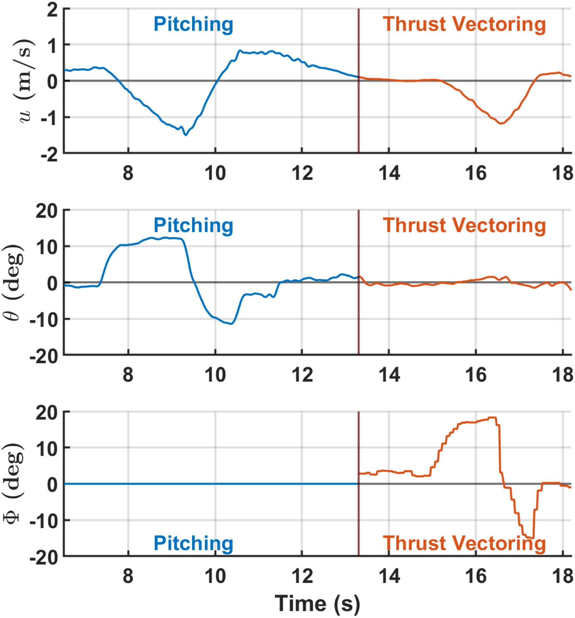
Test data showing longitudinal motion achieved via pitching and thrust vectoring in a single flight.
Conclusions
In this paper the flight dynamics of a 33-gram micro twin-cyclocopter in a hovering state were investigated via extracting a bare airframe Linear Time-Invariant (LTI) dynamic model from flight test data using time-domain system identification techniques. The current twin-cyclocopter, owing to its small size, cantilevered blade design, and counter-rotating coaxial-nose rotors, is a unique design configuration with significantly improved handling qualities, all of which make it distinct from other cyclocopters that have been built in the past. Previously flown cyclocopters developed by the authors were several times heavier, used doubly-supported rectangular blades, and utilized only a single nose rotor each. The aggregate effects of the reduced inertia, unique cyclorotor aerodynamics, and absence of nose rotor reaction moment allowed the micro twin-cyclocopter to demonstrate passive roll stability. The first and only cyclcopter to do so to date. The LTI model encapsulates many of these qualities in a simplified set of equations representing a complex dynamical system. A mode and frequency analysis was done on the system of equations that showed two stable modes and one unstable oscillatory mode. The key lessons learned from this study are enumerated below.
A torque and angular momentum balanced nose rotor system minimizes coupling, simplifies the trimming process, and significantly improves the handling qualities of the twin-cyclocopter. The current micro twin-cyclocopter was observed to be inherently (open-loop) stable in roll with two oscillatory modes. A strong gyroscopic coupling was experienced between roll and yaw due to the large unbalanced angular momentum of the cyclorotors. Smart control techniques were used to take advantage of the coupled nature of this vehicle to improve performance.
Footnotes
Funding
This research was partially supported by the U.S. Army’s Micro Autonomous Systems and Technology–Collaborative Technology Alliance (MAST-CTA) with Chris Kroninger (Army Research Laboratory–Vertical Technology Directorate) as Technical Monitor.
The work was also partially supported by Army/Navy/NASA’s Vertical Lift Research Center of Excellence (VLRCOE) led by the University of Maryland with Dr. Alex Moodie and Dr. Mahendra Bhagawat as Technical Monitors.
Declaration of conflicting interests
The authors declare that there are no potential conflicts of interest with respect to the research, authorship, and/or publication of this article.
Funding
The author(s) received no financial support for the research, authorship and/or publication of this article.