
Abstract
In order to solve the structural damage problem of the first generation of large multi-rotor manned drones, the present work has designed to study the structural vibration problems of multi-rotor drones. On a small multi-rotor drone, the laser vibration meter verified the reliability of acceleration sensor measurement of vibration and found that circular shape carbon fiber arms have strong damping abilities, with the strongest vibration in the Z-axis direction. To improve the design of the second generation of large multi-rotor manned drones, elliptical shape carbon fiber arms were employed instead of circular arms. Experiments showed that the main vibrations of the large multi-rotor manned drone’s arm are low-frequency vibrations below 200Hz, producing mainly torsional and bending modes, and the elliptical carbon fiber arms significantly reduce vibrations in the Z-axis direction. This study provides experimental data support for multi-rotor manned drones and further presents an improvement strategy for suppressing the vibrations of the multi-rotor manned drones.
Keywords
Introduction
Recently, with the rapid development of autonomous systems, the study of autonomous systems has become one of the hottest topics today. Unmanned systems, consisting of unmanned aerial vehicles (UAVs), unmanned ground systems (UGS), unmanned maritime platforms (UMVs), and unmanned space systems (USS), have great potential in both military and civilian applications.3,2,1 Among these, UAVs have a significant role in low and ultra-low altitude areas, and have unique advantages. Currently, UAVs have a wide range of applications in areas such as reconnaissance, attack, aerial photography, 4 forestry, 5 transportation, 6 disaster relie, 7 ), communication relay, 8 wildlife tracking, urban stability, mapping, power inspection,10,9 agriculture, 11 geological survey, 12 and border control. Traffic congestion is a problem that large cities must face, 13 due to the limitations of current transportation tools. There is an urgent need for new types of transportation to solve this problem. The manned drone technology has a natural advantage in dealing with complex urban environments, as it can fully utilize the low-altitude multi-dimensional space, ignore complex urban buildings, and quickly reach its destination. It is a good solution to the current traffic congestion in the cities.
Improving the autonomy of drone systems can be done by enhancing their level of intelligence, such as in environmental perception, 14 planning,16,15 and control. 17 However, there is less attention given to the structure of drones. As a new mode of transportation, the safety and comfort of passenger drones are undoubtedly important, so the structural damage caused by drone vibrations and the impact of noise should also be more widely recognized. DU et al. 18 developed an active-passive isolator for space-craft micro-vibration control, laying the foundation for the development of a Stewart platform with 6-DOF vibration isolation capability. Ortlieb et al. 19 proposed a general method for automatic risk assessment, providing a modular, data-driven framework for risk assessment in complex environments. Researchers have studied local vibration information on drones to improve stability, such as Verbeke and Debruyne, 20 who obtained sensitive electronic device installation locations through structural vibration analysis of small multirotor drones. Li et al. 21 designed a vibration-resistant module to protect sensitive electronic devices. Simsiriwong and Sullivan 22 obtained the corresponding vibration modal data of drone wings through experiments and used composite materials to reduce the impact of vibration. Hu et al. 23 studied the relationship between motor vibration and drone stability to prevent excessive motor vibration from causing greater damage to the drone during flight. There are also many researchers who have studied the overall impact of drone vibration, such as Russell et al. 24 used a wind tunnel to conduct experiments on multirotor drones to determine forces and moments and electric motor vibrations, and Dbouk and Drikakis 25 proposed a low-cost method for calculating the aerodynamic noise of multi-rotor drones. So it is necessary to pay more attention to the structural impact of drone vibration and to develop ways to reduce it in order to improve the performance of safety and comfort for passenger drones.
However, multi-rotor passenger drones are developing flying platform with limited reliable flight test data and published research, especially in terms of structural safety. Structural damage is often subtle and can only be discovered through long-term observation and testing. This research was conducted during the development of the first-generation passenger drone and found that vibrations during long-distance flight cause destructive damage at the key connections. During a certain experimental flight, we encountered a case of weld seam rupture, as shown in Figure 1. In other experimental flights, I frequently observed the phenomenon of loose bolts, so we perform the corresponding inspections before each takeoff.When weld seam rupture and significant bolt loosening occur, the stiffness and strength of the material/structure noticeably decrease. When we were towing the unmanned aerial vehicle to the maintenance site, we discovered that the cracks had expanded, indicating that the vibrations during transportation were sufficient to affect crack propagation. To further study the impact of vibrations on the structure of multi-rotor passenger drones for further improving the second-generation passenger drone. Inspired by the vibration experiments of small multi-rotor drones, computer-aided design tools were used to design the second-generation multi-rotor passenger drone. Through vibration mode simulations and experiments, it was found that effective reduction of arm z-axis vibration can be achieved. The results of this study provide a clear strategy for further optimization of multi-rotor passenger drones.
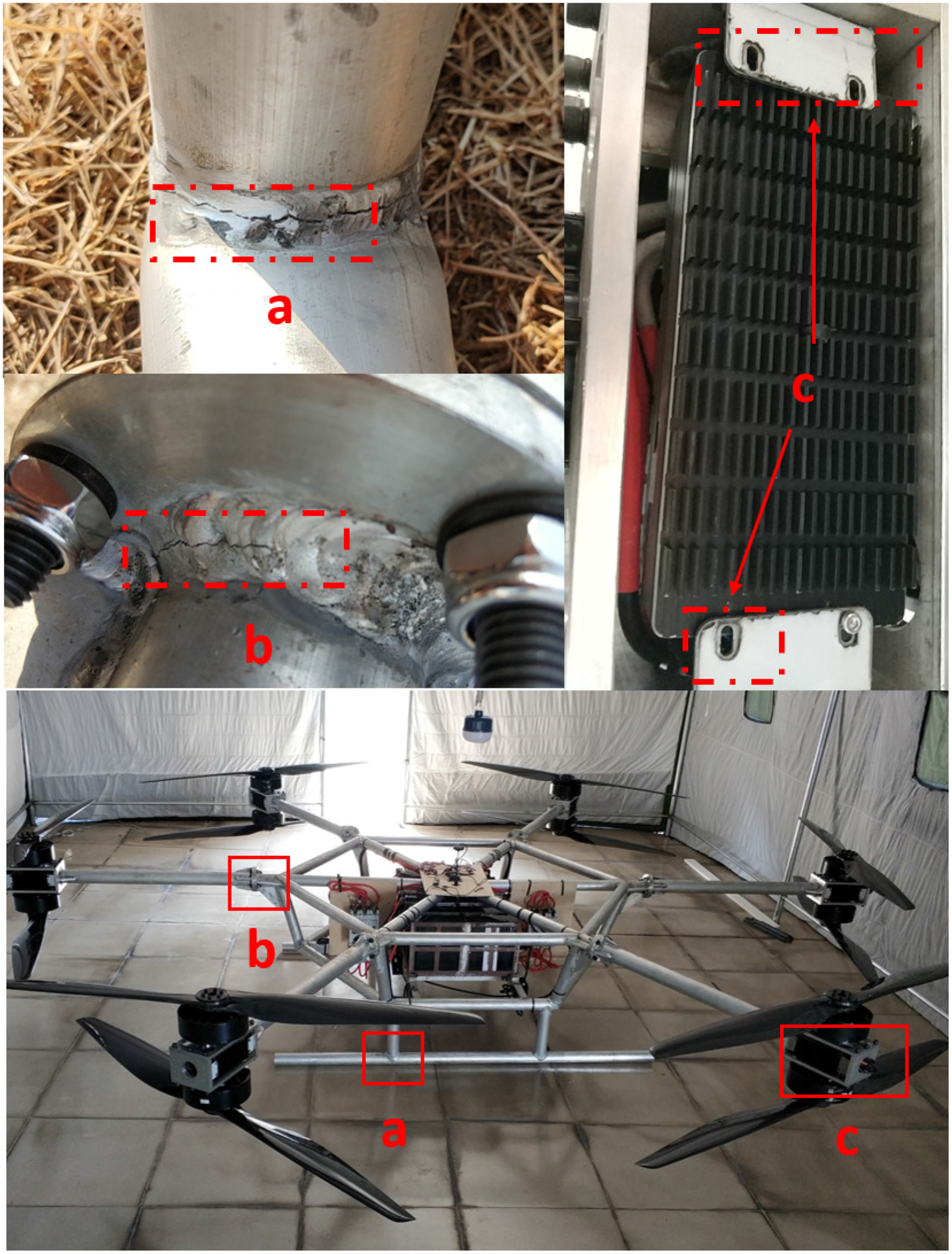
Vibration Damage to Critical Parts of Unmanned Aircraft, label a is the landing gear connection, label b is the arm and fuselage connection, label c is the fixed component installed below the motor.
This paper is structured as follows: Section II introduces the theoretical application of operational transfer path analysis method in vibration analysis of multi-rotor unmanned aerial vehicles. Section III presents the experimental and simulation of small multi-rotor unmanned aerial vehicles, verifying the feasibility of acceleration sensor measurements of vibrations, and providing ideas for the design of the second-generation large multi-rotor manned unmanned aerial vehicles. In Section IV, the vibration experiments and simulations of the second-generation drone are mainly introduced and improvement strategies are proposed. Finally, in Section V, the conclusions of this paper are summarized.
Operational transfer path analysis of multi-rotor passenger drones
Vibration is an expression of uneven energy distribution during transmission. The propagation of drone vibrations can be divided into two categories: structural transmission and air transmission. Structural transmission refers to the transfer of vibrations from the source through the structure of the drone to other parts. Air transmission refers to the transmission of vibrations from the drone through the air to the surrounding environment. For a multi-rotor drone model, vibration source analysis is relatively complex and can be roughly divided into the following four categories: (1) Motor rotation; (2) Propeller cutting through the air; (3) Drone collision with the ground during landing; (4) External disturbance to the drone.
Operational Transfer Path Analysis (OTPA)26,27 is a technique used to identify and evaluate the contribution of different components and subsystems to the overall noise and vibration level of a system. It works by measuring the transfer of energy within the system and analyzing the data to determine the sources and pathways of noise and vibration. This information can be used to design systems with reduced noise and vibration, or to diagnose and solve problems in existing systems. For a multi-rotor unmanned aerial vehicle, the electric motor driven propellers are the input of the system, while the points of interest of the system are the output, making it a typical multiple input multiple output system. For a multi-input multi-output arbitrary linear system, the target point response can be represented as:

To more conveniently obtain the transfer function H, we use the OTPA method, which only requires the determination of all elements of the transfer function from a single measurement, with all excitations present simultaneously. This more closely reflects the actual operating state of the system. This requires rewriting equation (1) in the following form:


Numerical and experimental of small multi-rotor passenger drones
There is little publicly available data on large multi-rotor passenger drones, and available data is limited, so researching this directly would be costly and potentially prone to errors. To quickly study large multi-rotor passenger drones, it is possible to start with smaller multi-rotor drones that are easier to research, quickly verifying the rationality of the experimental setup and finite element analysis, providing a theoretical basis and experimental verification for the modal analysis of large multi-rotor passenger drones. Providing data support for the design of the second generation of large multi-rotor passenger drones can improve the operational stability and safety of these drones.
Experimental modal analysis of small multi-rotor UAV
This section introduces the vibration sources and vibration analysis of critical parts of small quadrotor drones, particularly the vibration information of motors acting on motor mounts, and the connection points between arms and the drone. To accurately obtain drone vibration information, this study used the following measurement devices: 1) Polytec PSV-500 SCANNING HEAD scanning laser vibrometer; 2) ADXL357 three-axis acceleration sensor. The scanning laser vibrometer has a frequency range of

Measurement of a Vibration Sensor. PolytecPSV-500 SCANNING HEAD(left), 3-Axis Acceleration Sensor (ADXL357)(righ).
For drones, the motor driving the blades to cut through the air is the main vibration source, and under normal conditions, the vibrations generated by the motor driving the blades are relatively stable. Based on data obtained from long-term flight experiments of the first generation of multi-rotor passenger drones, we know that the attachments of the motor, the connection points between the arms and the body, and the landing gear are most likely to experience structural damage due to vibrations. In this study, we focused on the vibration modal information of the attachments of the vibration source and the connection points of the arms, and therefore measured the following four measurement points, as shown in Figure 3. We placed the UAV on an isolation platform to ensure that the vibration situation of the UAV hovering without external interference was simulated, and the remote control throttle was controlled at

UAV measurement of position points (top), test scene (bottom).
At the beginning of the experiment, we collected frequencies within the range of 0–2000 Hz and found that the vibration frequencies of the UAV were relatively low and the high-frequency vibrations were almost negligible. For convenience, we will only show the vibration data from 0 to 400 Hz in the following sections.
In the first set of experiments, we used the motor driving the propeller as the vibration source, started the UAV at

Vibration of UAV with Propellers.
In the second experiment, the propellers were removed and only the motor was used as the vibrational source. The collected data is shown in Figure 5. We found that in the absence of propellers, only higher vibrational frequencies could be excited and fewer vibrational modes were able to be collected, whereas in the presence of propellers, more low frequency vibrational modes were observed. The reason for this phenomenon is that the interaction between motors is smaller in the absence of propellers, resulting in the motors being in a more stable state. As a result, the UAV itself exerts less force and is unable to excite other modes. However, in the presence of propellers, the cutting of the air by the propellers causes the force acting on the UAV to be greater and also unbalanced. Additionally, even at the same throttle, the rotational speed of the motor will decrease in the presence of propellers.

Vibration of UAV without Propellers.
Due to configuration limitations, the laser vibration analyzer can only measure vibration in one direction, so we also used the three-axis accelerometer to collect vibration data. The accelerometer was installed on the back of the 2nd and 4th position points. As shown in Figure 6, the same conclusions as those obtained from the laser vibration analyzer experiment can be drawn. In addition, the data from the accelerometer measurement experiment also shows that the vibration in the z-axis direction is the strongest, while the vibration in the y-axis direction is the weakest. Because the vibration source is installed in the z-axis direction, and the energy is transmitted from the z-axis direction to other parts of the drone, so the vibration in the z-axis direction is the largest. In the process of axial transmission of vibration through the carbon fiber tube, the distance traveled is long and the energy consumed is also greater, so the vibration in the y-axis direction is relatively minimal. Compared to the laser vibration analyzer, the accelerometer can provide more vibration information. According to Figure 7, it can be seen that the accelerometer measurement data is highly consistent with the laser vibration analyzer measurement data, so the accelerometer can be used to replace the laser vibration analyzer in measuring drone vibration.
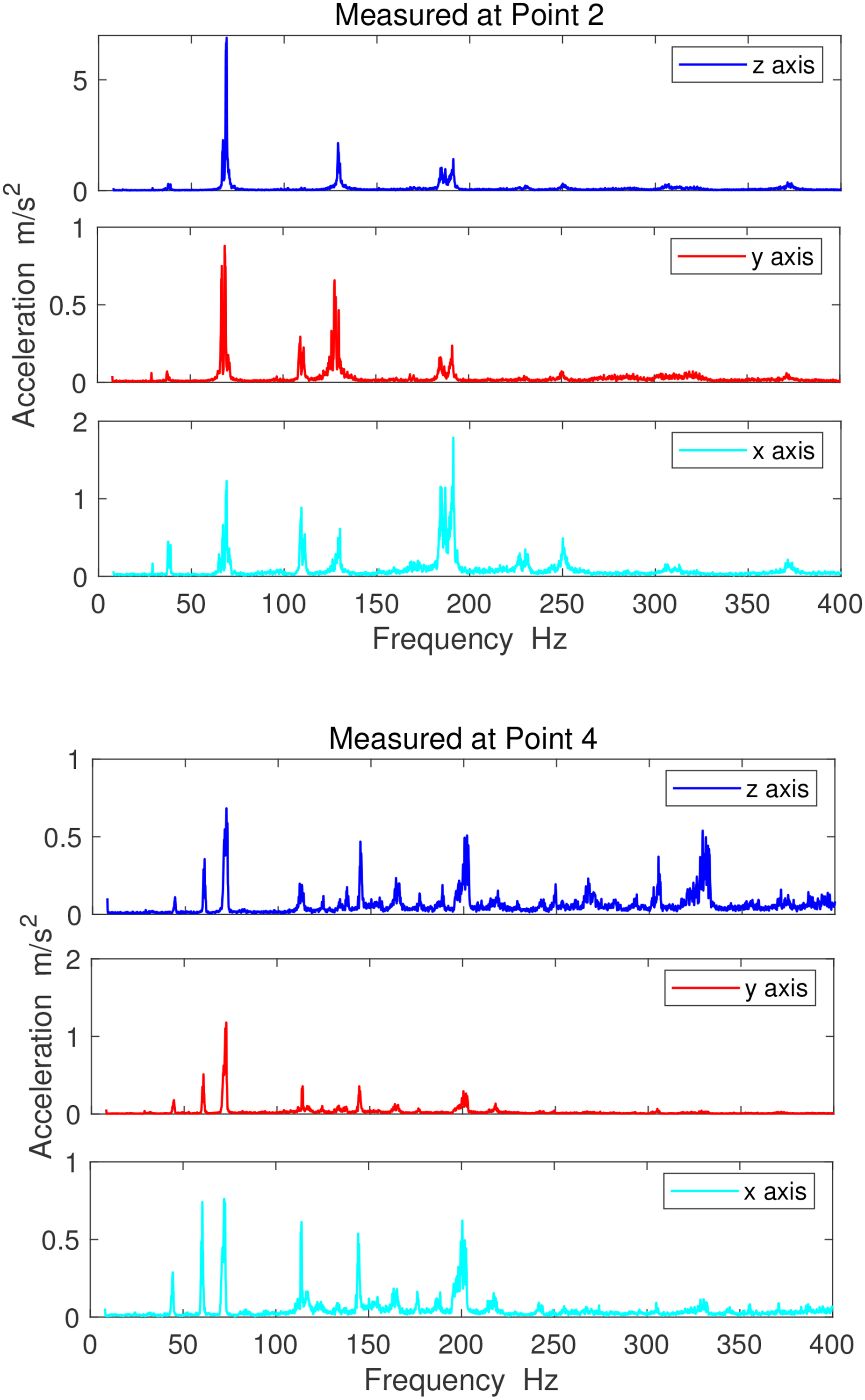
Accelerometer Measurements of Vibration Modes at 2 and 4 Points.

Accelerometer Measurements of Vibration Modes at 2 and 4 Points.
Finite element analysis of small multi-rotor UAV
A small quadrotor drone consists of four cylindrical carbon fiber tubes, four motor carbon fiber mounting plates, carbon fiber sheets, four motors, and various fixed blocks and landing gear, as shown in Table 1 for material properties.
Material properties of large octocopter passenger drone.

In order to improve the efficiency of mesh partitioning, we simplified the model by deleting insignificant electronic components, omitting unnecessary holes and corners, and making the mesh more uniform and smooth. For the small quadrotor drone, we set the mesh size to 5 mm for insignificant structural parts of the landing gear, and the default setting is 3 mm for the rest. Using the default system method to partition the mesh, we obtained 209015 nodes and 60438 elements, as shown in Figure 8. To improve the accuracy of the simulation, we replaced the mass of the drone’s electronic components and battery with mass points. The total added weight of the small drone was 0.52 kg. The modal cloud map obtained from the final solution is shown in Figure 9. Table 2 clearly shows that the experimental results are in agreement with the numerical analysis results.

Small quadrotor unmanned aerial vehicle grid division.

Small quadrotor unmanned aerial vehicle partial mode cloud charts.
Comparison of modal analysis and experiment results.

Large multi-rotor manned UAV
The first generation of large multi-rotor manned drones were made of aluminum alloy and specialty steel, and were welded by professional welders. However, during long-term experimental flights, cracks appeared in the welds at the connection between the arms and the fuselage, and there was a risk of looseness in the electronic components installed below the motors and some critical bolt positions, as shown in Figure 1. These connection points are repeatedly subjected to stress in the vibration during high-speed rotation of the motors, and the poor damping performance of aluminum alloy and steel materials makes them more prone to damage. The aircraft is subjected to great impact forces during takeoff and landing, causing serious damage to brittle materials such as welding. Based on our research experience on small multi-rotor drones, we have found that carbon fiber materials have excellent damping and attenuation performance. Additionally, as the transmission path increases, the vibration attenuation also increases. The radial shape of the cylinder along the Z-axis is consistent with the X-axis, but the vibration intensity is different. To reduce the vibration of the Z-axis, we attempted to alter its shape by making the Z-axis larger than the X-axis, thereby increasing its ability to dampen vibrations. Therefore, we designed the drone arm in an elliptical shape to reduce vibration in the Z-axis direction, and used carbon fiber material to replace aluminum alloy and steel, which not only fully utilizes the excellent attenuation performance of carbon fiber but also reduces the seams caused by welding.
Finite element analysis of large multi-rotor UAV
The large multi-rotor manned drones is composed of eight oval-shaped carbon fiber tubes, eight motors, eight carbon fiber propellers, a carbon fiber cockpit, and a structural steel landing gear. Its material properties are shown in Table 3. To facilitate calculations, the grid is divided into a 10 mm size with the default system method, resulting in 2468941 nodes and 1193793 elements, as shown in Figure 10. According to the modal cloud chart, it is clear that the main vibration modes of the arm are concentrated below 200 Hz, with three distinct modes at 15 Hz, 107 Hz, and 116 Hz, primarily in the form of bending and shear modes, as shown in Figure 11.

Large octocopter manned unmanned aerial vehicle grid division.

Large multi-rotor manned drone modal cloud chart.
Material properties of large octocopter passenger drone.

Experimental modal analysis of large multi-rotor UAV
Based on research experience with small unmanned aircraft, the measurement signals close to the vibration source (motor) can be used as the vibration source signal under working conditions. We measured the bottom of the motor’s cylindrical mounting base as the vibration source signal under working conditions and the connection point between the arm and the base as the response point, as shown in Figure 12. The resulting vibration modes are shown in Figure 13.

Accelerometer installation location.

Vibration of the large multirotor passenger drone motor at measurement points 1 and 2.
Based on experimental data, it can be seen that the radial vibration in the X-axis direction of the elliptical arm is greater than that in the Z-axis, while the experimental results in Section “Numerical and experimental of small multi-rotor passenger drones” indicate that the radial vibration in the Z-axis direction of the circular arm is greater than that in the X-axis. This shows that changing the shape can change the vibration decay. We speculate that increasing the stiffness in the Z-axis direction may be beneficial for vibration damping. The higher the stiffness, the less likely it is to excite low-frequency vibrations (which are mainly generated by the robotic arm). Additionally, the elliptical shape of the robotic arm increases the size in the Z-axis direction, making it even less susceptible to carbon fiber arm vibrations in the Z-axis direction. Similarly, the vibration source signal rapidly decays after passing through an elliptical carbon fiber tube under working conditions, which is consistent with the experiments of small multi-rotor drones. It was found that measurement point 1 is located at the bottom of the elliptical pillar electrical mounting seat, and when the vibration source signal is transmitted to measurement point 1, the vibration transfer path in the Z-axis is longer. At measurement point 2, the vibration passed through the elliptical carbon fiber tube, and its Z-axis was stronger than the X-axis, so the overall performance was that the vibration in the Z-axis was smaller than that in the X-axis. This is also consistent with the results of the small multi-rotor drone experiments. Table 4 clearly shows that the experimental results are in agreement with the numerical analysis results. The main modes of vibration generated by the multirotor UAV arms are torsion and bending modes, due to the arm being designed as a beam structure. Furthermore, the longer the arm, the more prominent these two modes become. Prolonged flight can accelerate the fatigue damage to the UAV and even compromise the connection components. In future designs, the impact of vibrations can be reduced by shortening the arm length. For example, increasing the number of joints between adjacent arms so they become a larger whole, or enlarging the cockpit which in turn shortens the arm length. Additionally, adding dampers to key locations of a multi-rotor drone, such as the motor mount, arm-to-body connection points, is also a good idea. In future research, we will aim to optimize the arms and ensure more secure and comfortable flight for multi-rotor drones by using more efficient propellers such as Toroidal propellers and incorporating damping mechanisms.
Comparison of modal analysis and experiment results.

Conclusions
In this study, a set of vibration mode analysis schemes for large-scale multi-rotor manned drones were developed based on experiments and finite element analysis of small-scale multi-rotor drones. We further demonstrated that accelerometers can be used to a certain extent to measure the vibration modes of drones, and developed a second-generation large-scale multi-rotor manned drone based on the vibration characteristics of small-scale multi-rotor drones, which achieved good results. Based on these experimental results in sections “Numerical and experimental of small multi-rotor passenger drones” and “Large multi-rotor manned UAV” of the article, we have found that for multi-rotor drones, circular tubular arms have the strongest vibration in the z-axis direction and the weakest in the y-axis direction. However, if the elliptical arm is used, the vibration in the z-axis direction is effectively reduced, with the vibration frequency mainly concentrated within 200 Hz and primarily producing torsional and bending modes.
Based on our current experimental observations and data, we have found that the motor mounting position and the connection between the arms and the body are particularly sensitive to vibrations. Additionally, the longer the arm, the more noticeable the vibration. To mitigate the risk posed by the beam structure, adding connecting structures between adjacent arms can reduce vibration.
Footnotes
Declaration of Conflicting Interests
The author(s) declared no potential conflicts of interest with respect to the research, authorship, and/or publication of this article.
Funding
This study is funded by Shenzhen Science and Technology Program (Grant No. GXWD20201231165807008, 20200830220051001), the Department of Science and Technology of Guangdong Province (2019QN01G064).