
Abstract
This study presents the design, implementation, and assessment of a combined passive and active flow control technique with the aim of increasing the aerodynamic performance of fixed-wing Micro Air Vehicles (MAVs). Power consumption restrictions in MAVs support the choice of passive flow control solutions such as the use of a modified (tubercled) wing leading edge. This strategy successfully allows to delay and mitigate aerodynamic stall but detrimental effects are found at pre-stall operating conditions. In order to retrieve the lift-generation capabilities of the baseline wing at pre-stall, a subsidiary active flow control method making use of air blowing was designed and installed in the modified wing. Guidance to the selection of optimum settings was provided by experimental and computational analyses. The resulting hybrid flow control system demonstrated its effectiveness, thus producing generalized lift enhancements irrespectively of the attitude of the wing.
Introduction
Over the past decade, solutions of several engineering problems have been found by inspiration from Nature, thus motivating a renewed focus on various research subjects. In recent years, the use of leading-edge tubercles in airfoils, wings, hydrofoils, fans, and turbine blades have received increased attention by scientists from different areas as a novel passive flow control (PFC) technique. The original idea was inspired by the pectoral flippers of humpback whales, which are capable of performing acrobatic maneuvers, tight curves at high speed, banked turns, as well as loops and rolls.1–3 The morphology and position of the leading-edge tubercles reveal that these enable lift enhancements via flow control over the whale's flipper, thus maintaining lift at high angles of attack
4
and, eventually, achieving stall delay.
5
Such interesting abilities have attracted the aerodynamicists’ interest in order to take advantage of the same methodology in real wings, especially in Micro Aerial Vehicles (MAV). Due to the small size and low velocities of MAVs, these operate in the low Reynolds number regime (Re < 200,000) where viscous effects dominate, involving phenomena such as laminar separation, transition, reattachment, and unsteady flow,
6
which generally degrades the efficiency of lifting surfaces. Various studies have demonstrated that the use of leading-edge tubercles may help in abating penalties associated with the low Reynolds number flow regime. Initial investigations focused on very specific high-aspect-ratio tapered wings as an attempt to mimic a real whale flipper, both from the experimental
5
and computational points of view.
7
More recently, Particle Image Velocimetry (PIV) measurements have been carried out as well for different airfoil geometries,8,9 bringing additional insight about the physical mechanisms behind this type of flow control.
10
In parallel to the experimental efforts, numerical predictions of the flow around the baseline and modified wings have subsequently been performed employing panel methods,
11
Reynolds-Averaged Navier-Stokes (RANS) approaches using different turbulent modelings such as Spalart Allmaras,
12
At low Reynolds numbers, the resistance to boundary layer separation is poor in the majority of (baseline) airfoils, which are prone to stall due to the establishment of strong adverse pressure gradients at high angles of attack. Conversely, airfoils with a (modified) wavy leading edge induce streamwise vorticity into the flow, thereby imparting momentum into regions where deficits are present (namely the boundary layer), and thus delaying the occurrence of stall. 29 Figure 1 summarizes the main results of a study 28 employing a sinusoidal leading edge (SLE), clearly evidencing the advantages of this biomimetic strategy as a passive stall control technique, specifically concerning its impact on post-stall lift coefficient, CL. However, these investigations have also identified the appearance of locally separated flow, characterized by the formation of a laminar separation bubble (LSB) on the suction side, even at relatively low incidences (i.e., at pre-stall operating conditions). This was not merely a consequence of the use of relatively thick wing sections, but rather a consequence of the leading-edge modification. The LSB changes the effective shape of the airfoil section and consequently, the aerodynamic performance is degraded. 30 A decrease in lift is observed in the pre-stall regime, as might be anticipated. Hence, an active flow control (AFC) method may still be useful to retrieve the original lift-generation capabilities of the baseline wing at pre-stall operating conditions.

Gains and losses in lift characteristics with respect to the baseline for a finite wing with a SLE operating at Re = 140,000. Experimental data from Guerreiro and Sousa. 28
The ability to control LSBs is a great challenge but, if accomplished, such achievement may lead to a class of air vehicles that are aerodynamically very efficient. Well-known methods for that purpose involve forcing premature turbulent transition, which suppresses the LSB or reduces its extension. Therefore, manipulation of the shear layer reattachment as well as of the turbulence upstream separation helps to avoid the formation of LSBs. 31 This is achieved via passive methods32,33 by selecting a specific airfoil shape or by installing mechanical turbulators upstream of the laminar separation point; or via active methods 34 using pneumatic turbulators, acoustic excitation, and plasma actuators. It is recognized that PFC operates well at the design point but cannot manage the flow as effectively at off-design conditions. On the other hand, the application of AFC requires energy expenditure. Therefore, a way out to overcome the intrinsic pitfalls can be found by combining both techniques, given that the AFC would actuate only at the required regime. This hybrid technology would be desirable in applications where a system must perform under a wide range of operating conditions.
As an active control device, the effectiveness in the use of plasma actuators for separated flows has been demonstrated in a variety of studies.35–37 This methodology consists of a pair of electrodes separated by a dielectric material, typically arranged in the asymmetric configuration. 36 However, a well-known disadvantage of these actuators lies in their requirement of large voltage inputs, which are necessary to drive the actuators, and consequently heavy amplifiers are needed for the adequate voltage supply.35,38 In MAV applications, a bulky system may not be a feasible choice as it becomes too costly in payload, virtually damaging flight endurance, and ultimately offsetting any gains in aerodynamic performance. Furthermore, a large actuator profile above the wing surface may inadvertently trip the flow, causing premature separation or an early transition to turbulent flow, thus increasing the skin friction drag. To circumvent these difficulties in MAV applications, micro-flow control devices, such as pneumatic turbulators, are of particular interest,39,40 whereas several investigations have been carried out in other fields as well. These turbulators blow high-momentum air jets inside the boundary layer at stations where the boundary layer would be likely to separate. A few years ago, control of the flow over a NACA2415 airfoil exhibiting a LSB at a transitional Reynolds number of 2 × 10⁵ was computationally investigated using blowing or suction. 41 In addition, AFC achieved via steady normal blowing was employed at a Reynolds number of 6.4 × 10⁴ on a NACA 643−618 airfoil, where the blowing ratio was optimized by maximizing the lift coefficient for the requirement of minimal power. 42 In a similar investigation, tangential blowing has been applied inside the LSB. 43 Another method to control the LSB has been used by Choi and Kim, 44 who have studied the use of a pulsating jet to manipulate the separated flow behind a fence. The results of this experiment have shown that specific values of frequency, position and injection angle yield a reduction of the time-mean length of the separation. Combined suction and blowing may also be used to control the LSB. 45 In addition, zero-net-mass-flux injection devices have been developed for the same purpose, 46 but mass injection into the bubble may be more effective, causing a mass imbalance, and affecting also the shear layer entrainment characteristics. 47
It is noteworthy that the LSB formed over standard (or baseline) wing surfaces usually spreads out along the spanwise direction. Hence, numerous pneumatic actuators must be installed on the pressure surface of the wing to achieve effective control, which may not be practical. In contrast, the pressure gradient along the spanwise direction of a SLE wing constrains the tendency of the LSB to eventually cover the whole wing span. As a consequence, a (minimal) localized momentum input into the flow over this modified wing may attain a larger effect in the latter case. On the other hand, the geometrical modifications required by the SLE complicate the use of AFC owing to additional space restrictions for equipment installation imposed by the scalloped leading edge. Therefore, coupling a micro-pneumatic actuator with the leading-edge modification is proposed in the present work, as a practical means of achieving an improved stall control strategy for low Reynolds number operation.
In the current study, a combined AFC and PFC system is experimentally and numerically investigated to improve the aerodynamic performance of a fixed-wing MAV prototype across a wide range of attitudes. The PFC element of the method is based on a leading-edge modification of the wing with biomimetic inspiration, using a sinusoidal shape to improve stall behavior. However, this technique leads to the establishment of a LSB on the suction surface of the SLE wing at pre-stall operating conditions, ultimately causing a reduction in lift generation at this regime. Proposing and investigating a feasible strategy to solve this problem is the main objective of this work. This has been accomplished by introducing the use of micro-air blowing as the AFC component of the methodology. Since reaching the maximum efficiency of the combined AFC and PFC system is also a goal of this study, actuators with two different cross-sectional areas and a variety of flow rates have been explored to find optimized operating conditions.
Experimental apparatus
Wind tunnel testing and model specifications
The present experiments were carried out at a low-speed, open-circuit wind tunnel. The test section of this facility has a cross-sectional area of 1.35 × 0.80 m2, where free-stream velocities up to U∞ = 10 m/s can be achieved with a turbulence intensity of about 0.3% in the potential core of the open jet. The instrumentation includes continuous monitorization of the air temperature and operating dynamic pressure, together with a custom-made six-component Schenck compact balance for the measurement of aerodynamic forces (and moments if required), employing a single-strut model support connected to the load cells. A Stereo Particle Image Velocimetry (SPIV) system by Dantec Dynamics further allowed conducting whole-field measurements of the flow around the wing models in the wind tunnel. 23 Its basic characteristics are as follows: a) A DualPower 200-15 YAG laser by Litron, operated as a frequency of 10 Hz with pulse energy of 2 × 190 mJ @ 532 nm (the laser pulse separation was typically set to 0.1–0.2 ms, following optimization of the image correlation in views from both cameras; the thickness of the light sheet was approximately 3 mm); b) Two digital cameras FlowSense 4 M with a resolution of 2048 × 2048 pixels, equipped with objectives Macro Zeiss 50 mm; c) Data analysis was performed by DynamicStudio 2015a software, typically using 32 × 32 pixels interrogation windows with an image overlap of 50% (two levels of multi-pass processing were applied with the aim of extending the dynamic range of the measurements 48 ).
With the objective of maximizing the field of view when the test models were positioned at moderate to high incidence, the experimental setup was arranged as depicted in Figure 2. Accordingly, one camera was installed perpendicularly to the laser light, which in turn was at right angle to the planform of the wings, whereas the other camera was tilted by an angle of 34 degrees. In-plane velocity measurements were made using the first camera only, though the combined use of both cameras was required in tests where the measurement of the out-of-plane velocity component was also desired. Adequate camera mounts and a fully computer-controlled 4-axis translation system by Isel Automation made it possible to keep the system aligned and focused in Scheimpflug condition, even during a spanwise field survey. Flow seeding was provided upstream of the wind tunnel plenum by a 1500 W commercial smoke generator with Digital Multiplex control. More details concerning the full characteristics of this experimental facility and instrumentation are given elsewhere.28,49

Planform view of the experimental setup used with the SPIV system.
Concerning the wing model, an MAV wing prototype was built in thermoformed Acrylonitrile Butadiene Styrene (ABS) plastic, a polymeric material, using additive manufacturing. Briefly, the section of the baseline (i.e., straight leading edge) wing model was designed to match the NASA LS(1)–0417 airfoil. A modified wing model with protuberances forming a SLE was also designed by adjusting the shape of the latter airfoil to a sinusoidal variation about the mean chord. The values for the geometrical parameters characterizing the wavelength and amplitude of the SLE were chosen in a previous study, 28 corresponding to 6% and 12% of the chord, respectively. In addition, a wing aspect ratio of 1.5 and a mean chord c = 232 mm were used. The data yields a Reynolds number Re = 140,000 (based on U∞ and c), within the typical range of operation of MAVs.
In the wind tunnel, the aerodynamic balance was used to quantify the lift and drag coefficients for a wide range of angles of attack α, with increments of 1 degree, from 8 to 25 degrees. The operating dynamic pressure was monitored employing a micromanometer (model FC012 from Furness Controls Limited), with a maximum error of 0.02 mm of water column within the tested range. Bias uncertainties affecting the force coefficients yielded maximum uncertainties of ±5% within the tested range, for overall 95% confidence limits. Wind tunnel corrections taking into account weight tares, load component interactions and open jet operation, as well as model-mount interaction, were also applied to measured forces. These measurements were complemented with the SPIV analysis carried out at four selected angles of attack, namely 5, 12, 16 and 20 degrees, thus covering both the pre- and post-stall regimes. All experimental data obtained were normalized using free-stream values.
Design of the AFC system
The laboratorial implementation of the micro-air blowing system consists of a small, off-the-shelf AirTech compressor, a Purgemaster flow meter series A6131/41, PVC tubes, and air injectors with two different cross-sectional areas, namely 0.5 and 1 mm2. A different supply option should be considered in real flight, possibly making use of high-pressure regions in the flow around the fixed-wing MAV, but this procedure was not yet explored at this stage. Since the primary goal of the AFC system is to suppress the LSB at pre-stall operating conditions by energizing the boundary layer near the wall surface, the micro-air jets must be as tangential to the surface as possible, and the injectors must be placed at optimum locations. Initially, the SLE wing with AFC off was experimentally tested at pre-stall operating conditions, namely at α = 16 degrees. The flow map obtained from the SPIV system allowed an accurate characterization of the region of flow reversal due to the presence of the LSB at a trough section of the wing prototype. As schematically shown in Figure 3, flow separation occurred in the troughs at a distance of approximately 26% of the (mean) chord from the peak of the leading-edge protuberance. Air injectors should ideally be placed at the exact centerline of the troughs in the SLE wing. However, the wing prototype has structural ribs at those locations. The alternative found consisted on the installation of a pair of injection holes equally spaced from the centerline at each trough segment of the wing. Provided that the injectors’ mass flow rate is sufficient, the flow reversal at the LSBs would be counterbalanced by the pair of jets, depending on their distance from the centerline. With this goal in mind, the optimum value for the foregoing distance may be slightly smaller than half of the width of the LSB.

Time-averaged flow map from SPIV at a trough section of the SLE wing for α = 16 degrees, with AFC off, illustrating the location of the separation point.
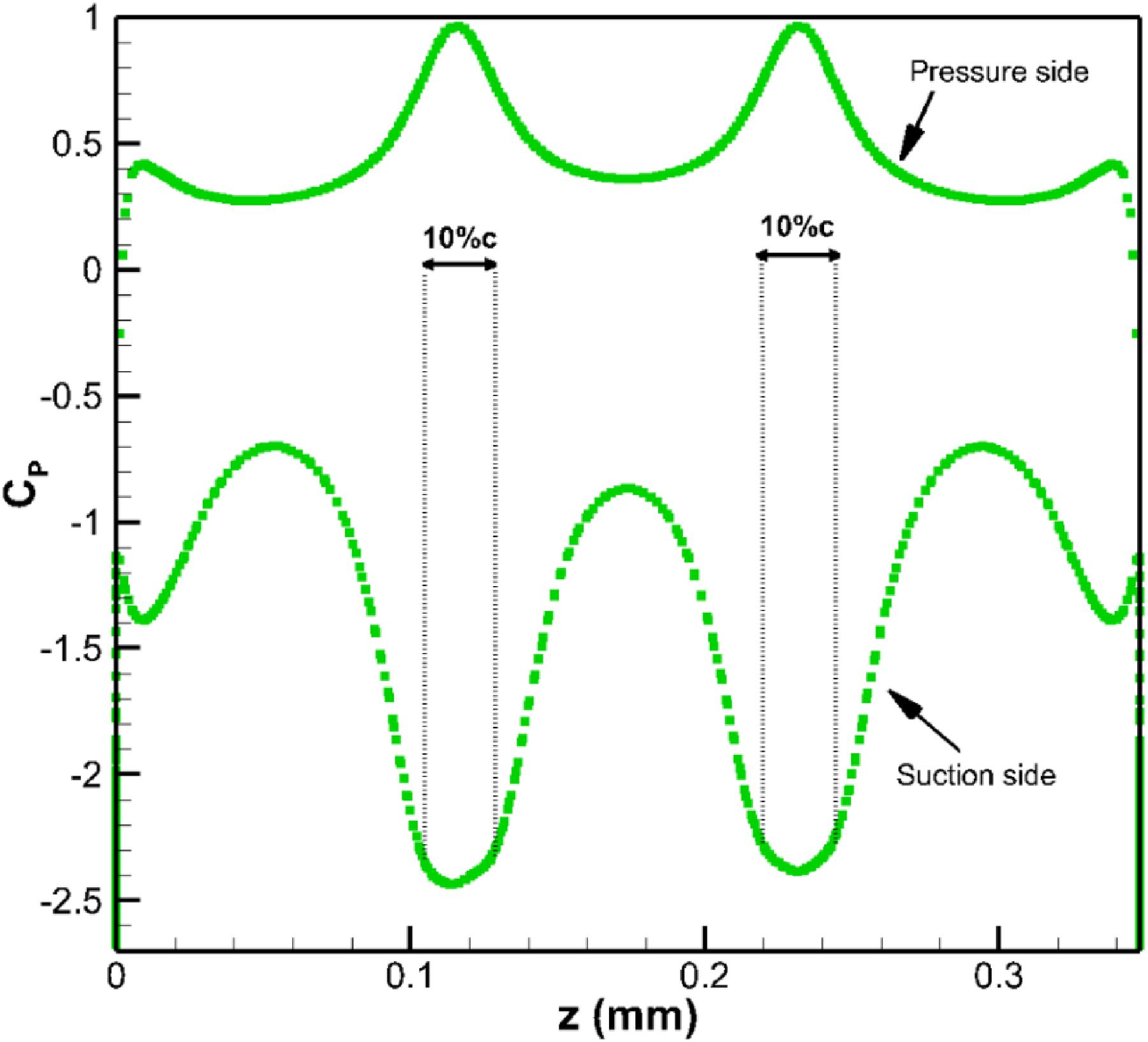
Although spatial information concerning the LSB has been obtained experimentally using SPIV, detailed pressure data for design purposes was gathered via numerical simulations of the flow around the wing for the same operating conditions. 49 The resulting time-averaged pressure coefficient distribution across the wingspan (as shown by the dashed line in Figure 3) is illustrated in Figure 4. It can be seen that the width of the LSBs is approximately 10% of the chord length c, which provides guidance to the separation distance between the pair of injection holes, in agreement with the previous considerations. The location of these holes is schematically depicted in Figure 5(a), and the micro-air injectors were carefully glued to minimize relative motion due to possible vibrations in the structure of the SLE wing. Additionally, Figure 5(b) provides a view of how the tubing of the AFC system was installed inside the wing prototype.

Installation of the AFC system in the SLE wing prototype: (a) placement of the injection holes; (b) tubing inside the wing.
The basic function of the AFC system consists of energizing the boundary layer near the wall, within the trough regions. As mentioned earlier, this is more efficiently achieved with tangential air injection. Dedicated computational simulations with AFC on, conducted in the framework of the present study (to be described later in this paper), indicated the adequate orientation and surface angles of the micro-air jets to be used in the experiments, corresponding to β = 45 degrees and θ = 40 degrees, respectively. The high values of these angles may be surprising, but it must be noted that a pair of injectors rather than a single one is being used, and the chosen value of θ is indeed consistent with that of a tangential jet due to the larger surface inclination of the wing surface at trough regions, as may be observed in Figure 6.

Micro-air jets of the AFC system in the SLE wing: (a) orientation angle; (b) surface angle.
For the quantification of the amount of air injected into the boundary layer, a momentum coefficient is defined, which is given by the ratio between the momentum of the jet and that of the free-stream flow, as follows:


Pneumatic characteristics of the AFC system for a single injector.
Setup of the numerical simulations
Regarding the numerical simulations, a computational mesh with a structured C-H topology was generated around the finite wing employing hexahedral elements, as illustrated in Figure 7. Mesh cells were locally refined in terms of resolution, grid size limitation, and other characteristics compatible to the experimental conditions. 24 No-slip conditions were applied at all solid wall surfaces, and the remaining domain borders were set to far-field boundaries, located at a distance of about 20c around the wing in order to make confinement effects negligible in the analysis. An exception was made only at the outflow section where a simple open boundary condition was used, implemented at a distance of 12c downstream from the trailing edge of the wing. Aiming to avoid inverted cell volumes and high skewness in the computational mesh, the least possible distance of the first cell nearest to solid walls was applied, while preserving a maximum value of this wall-normal length expressed in wall units close to unity, as a fundamental requirement for the Detached-Eddy-Simulation (DES) approach 51 chosen for the present investigation. In the cases where flow actuation was considered, local mesh refinement has been applied to adequately simulate the presence of the micro-air injectors.

Close-up view of the computational mesh around the SLE wing without AFC.
The unsteady Navier-Stokes equations under constant properties and the incompressible flow assumption were solved within the flow domain employing a second-order accurate finite volume scheme. Concerning turbulence modeling, two different hybrid RANS/LES procedures have been applied taking into account previous findings in the analysis of the SLE wing without AFC. 49 Hence, whereas the Improved-Delayed-Detached-Eddy-Simulation (IDDES) method was selected 52 to deal with pre-stall conditions, the Delayed-Detached-Eddy-Simulation (DDES) method with a shielding function F2 was used instead to tackle the post-stall regime. 24
The time step used in the flow simulations reported herein is 0.0025 s, though this value has been halved at a preliminary stage with the objective of confirming time step independence. Often, the simulations had to be carried out longer than 40 s in order to reach a statistically converged unsteady state unaffected by initial transients. Time-averaged results were typically computed from 400 instantaneous realizations of the flow, covering about 10 s of simulation time.
Results and discussion
Strengths and weaknesses in passive flow control
As seen earlier in Figure 1, the leading-edge modification is beneficial at post-stall angles in comparison to the baseline wing, but the overall wing efficiency is somewhat damaged, especially at pre-stall operating conditions. Before considering a remedy for the foregoing problem, the root of the phenomenon must be duly characterized. To this aim, SPIV images together with numerical simulations provided us with details about the flow field. Previous SPIV analyses indicated that a LSB forms on the suction side of SLE wing, at the trough cross-section, whereas it is absent in the baseline wing for the same operating conditions. Figure 8 shows time-averaged flow maps at the trough section (referring to the SLE wing), for both the modified (SLE wing) and baseline wings of unity aspect ratio operating at α = 15 degrees, as studied by Esmaeili et al.. 49 The separated flow changes the effective shape of the wing and, consequently, the accelerated flow region in the suction side shrinks when compared to that observed in the baseline wing. A detrimental impact of the geometrical modification on the corresponding aerodynamic coefficients is therefore anticipated at pre-stall operating conditions.

Time-averaged flow maps from SPIV at the trough section and α = 15 degrees (pre-stall) for (a) modified unity aspect ratio (SLE) and (b) baseline wings without AFC, as studied by Esmaeili et al 49 .
One must bear in mind that, at investigated (low) Reynolds number, viscous effects dominate. Due to the decrease in momentum at the troughs of the SLE wing, the boundary layer is no longer able to remain attached to the wing surface. Following laminar separation, the resulting flow pattern induces transition from laminar to a turbulent regime. Since the flow outside the boundary layer is more energetic, the turbulent mixing process redeploys high-momentum fluid into the separated layer, thus opposing the adverse pressure gradient. Eventually the flow is squeezed to reattachment, giving rise to the establishment of a LSB. It may be expected that parameters such as the Reynolds number, incidence angle, wing shape, surface roughness and free-stream turbulence will play a significant role on the dynamics of the phenomenon. However, it is the balance between two main factors, i.e., high-momentum flow and adverse pressure gradient, ultimately defining the length of the LSB. Additional details about the flow field can be obtained from numerical simulations, allowing to clarify further the physical mechanisms involved. As concluded in a previous investigation, 24 RANS models exhibit a poor performance in the presence of separated flow. An exceptionally high mesh resolution in wall-bounded flows would be required by the use of resolved turbulence models, such as LES, thus increasing the computational costs enormously. Hence, the hybrid RANS/LES modeling selected for this study presents an attractive approach, as it combines the advantages of both RANS and LES models. The IDDES model, which in turn combines wall-modeled-LES and DDES, is recommended for pre-stall conditions due to the presence of significant extensions of attached flow.
In summary, the increased relative thickness characterizing trough sections of the SLE wing leads to an intensification of the suction peak at these locations, which is consequently followed by a stronger adverse pressure gradient as well. At relatively low Reynolds numbers, the laminar boundary layer separates, but early transition to turbulence still allows negotiation of the pressure recovery so that a LSB is formed, provided that the angle of attack is not too high. Overall, this results in a slight reduction of lift at pre-stall operating conditions, and earlier occurrence of stall, though the phenomenon itself becomes smoother (Cf. Figure 1). Increasing the wing incidence strengthens the adverse pressure gradient further, and bursting of the LSB might be expected to occur, leading to the establishment of massively separated flow over the wing. However, the tubercles in the modified wing inhibit spreading of separated flow to the entire (upper) wing surface at post-stall angles of attack. In fact, PFC remains very effective at such operating conditions, with corresponding benefits in lift. This is illustrated in Figure 9, showing that the increase of the angle of attack to 20 degrees (post-stall condition) produces only a moderately enlarged region of recirculating flow, rather than massive separation at the trough section.

Time-averaged flow map from SPIV, at z = 3/4c (trough section) and α = 20 degrees (post-stall), around the SLE wing without AFC.
Combined active and passive flow control
Effect of the jet velocity ratio
Aerodynamic data to characterize the performance of the pneumatic actuator system in the SLE wing prototype were gathered from experiments. Initially, the larger injectors (cross-sectional area of 1 mm2) were installed in the wing, and three different values of the jet velocity ratio (Cf. Table 1) were examined. As a preliminary assessment of the AFC system, the measured lift coefficients produced by the SLE wing with AFC off were compared to those with AFC on in Figure 10, at Re = 140,000 for a range of incidence angles from 8 to 25 degrees.

Evolution of the lift coefficient with the angle of attack with AFC off and on in the SLE wing, for various values of the jet velocity ratio and injectors with a cross-sectional area of 1 mm2.
In all cases, the lift coefficient increased almost linearly with the angle of attack up to the point where a (smooth) reduction was observed, signaling the occurrence of stall in the modified wing. At higher incidences, in the post-stall regime, lift values eventually increase again. It can be seen that with the AFC system set for the lowest value of the jet velocity ratio, Uj/U∞ = 0.7, improvements were not obtained in comparison to the reference case (AFC off). Conversely, this operating condition led to earlier stall (at α = 15 degrees rather than 16 degrees), and a reduction in peak CL by about 5%. Hence, in this case, the supply of momentum from the micro-air jets into the LSB was not sufficient to wash it out, contributing to its destabilization only. In contrast, when the jet velocity ratio was more than doubled to the value of 1.5, CL was successfully increased at pre-stall, but the stall angle remained unchanged with respect to AFC off. A slight improvement in the behavior at deep stall, when compared to the reference case, was also observed. Further increasing the jet velocity ratio to 2.9, for a better understanding of the effects of this AFC, produced similar results to those obtained for the intermediate tested value of Uj/U∞ at pre-stall. However, the higher momentum of the micro-air jets also allowed delaying the occurrence of stall, which was accompanied by an increase in peak CL, as well as a major improvement of the behavior in post-stall operation.
Flow patterns captured by SPIV at a trough section (z = 3/4c) of the SLE wing, for the various micro-air jet characteristics analyzed, have provided additional insight about the physical mechanisms involved. In Figure 11, the corresponding time-averaged flow maps are compared at α
Time-averaged flow maps around the SLE wing from SPIV at z = 3/4c (trough section) and α = 12 degrees, for (a) AFC off, and AFC on with (b)
In turn, a similar analysis was conducted at α

Time-averaged flow maps around the SLE wing from SPIV at z = 3/4c (trough section) and α = 16 degrees, for (a) AFC off, and AFC on with (b)

Time-averaged flow maps around the SLE wing from SPIV at z = c (center peak section) and α = 16 degrees, for AFC on with (a)
Earlier in this paper, a comparison with SPIV data demonstrated that the present numerical approach was able to provide a correct description of the flow around the SLE, without AFC (reference case), at pre-stall conditions. However, the use of numerical simulations in the design of the AFC relied on the hypothesis that this capability holds when flow actuators are also employed. For the case of AFC on with

Time-averaged flow map from numerical simulations (IDDES), at z = 3/4c (trough section) and α = 16 degrees, around the SLE wing with AFC on, and
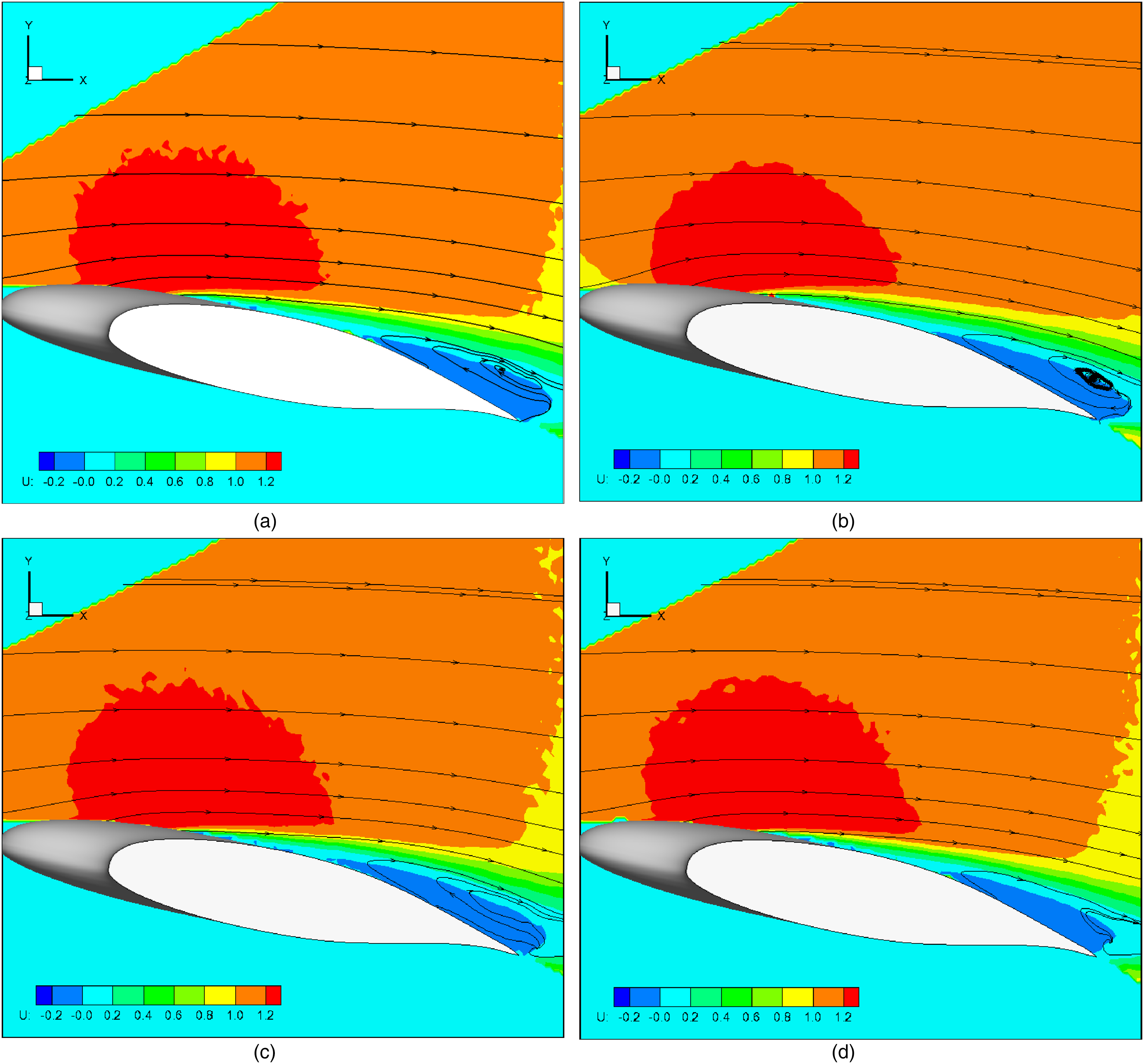
The conformity between the results of experiments and numerical simulations at pre-stall conditions gives confidence to carry out a more in-depth analysis of the flow features based on the latter approach. Hence, Figure 15 portrays the computed evolutions of the mean pressure coefficient Cp for both the reference case (AFC off) and the case of AFC on with a jet velocity ratio of 2.9, compared at a trough section of the SLE wing. It can be seen that the impact of the actuators on the pressure distribution over the upper surface extends beyond 50% of the chord. A strong suction peak at the leading edge is present in both cases due to the moderate incidence of the wing (α = 16 degrees), but it has been intensified by the AFC (in this case). However, as observed earlier in the flow maps, the major difference between these two cases concerns the LSB. With AFC off, a large plateau in Cp is observed, associated to a substantial length of recirculating flow. The extent of this region is drastically reduced for
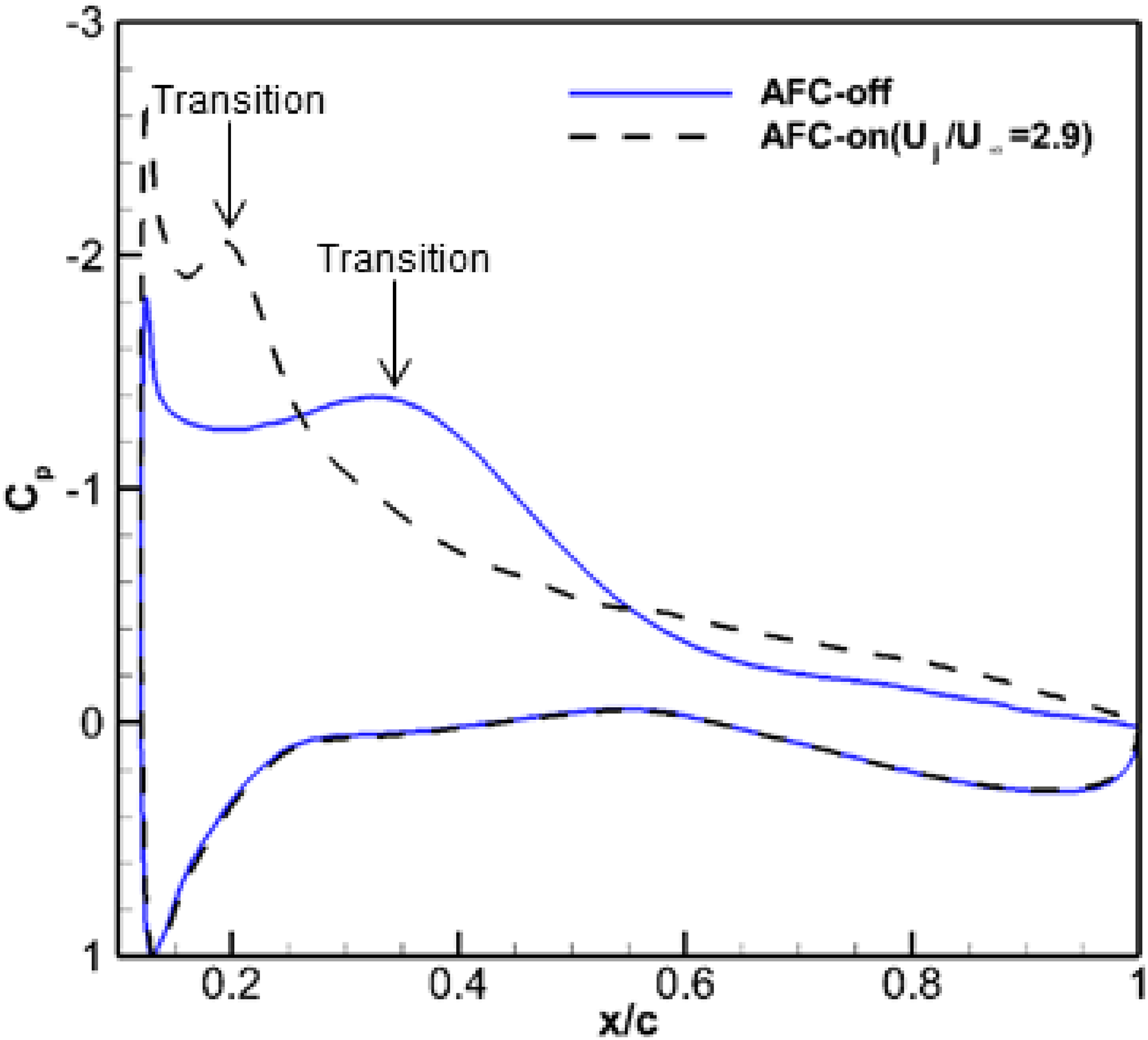
Computed time-averaged pressure coefficient distribution over the SLE wing, at z = 3/4c (trough section) and α = 16 degree, for AFC off, and AFC on with
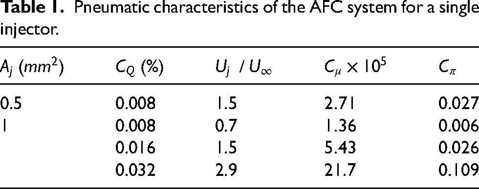
Focusing now in post-stall operating conditions, one should recall that the measurements of lift coefficient (Cf. Figure 10) have indicated that switching the AFC on with a small jet velocity ratio was prejudicial, leading to the earliest occurrence of stall in the SLE wing. This mechanism is better understood based on the flow maps presented in Figure 16, where a comparison between the results for two different settings of the AFC system is made at a trough section of the SLE wing, for α = 20 degrees. Figure 16(a) is illustrative of a manifestation of “bubble bursting” associated to
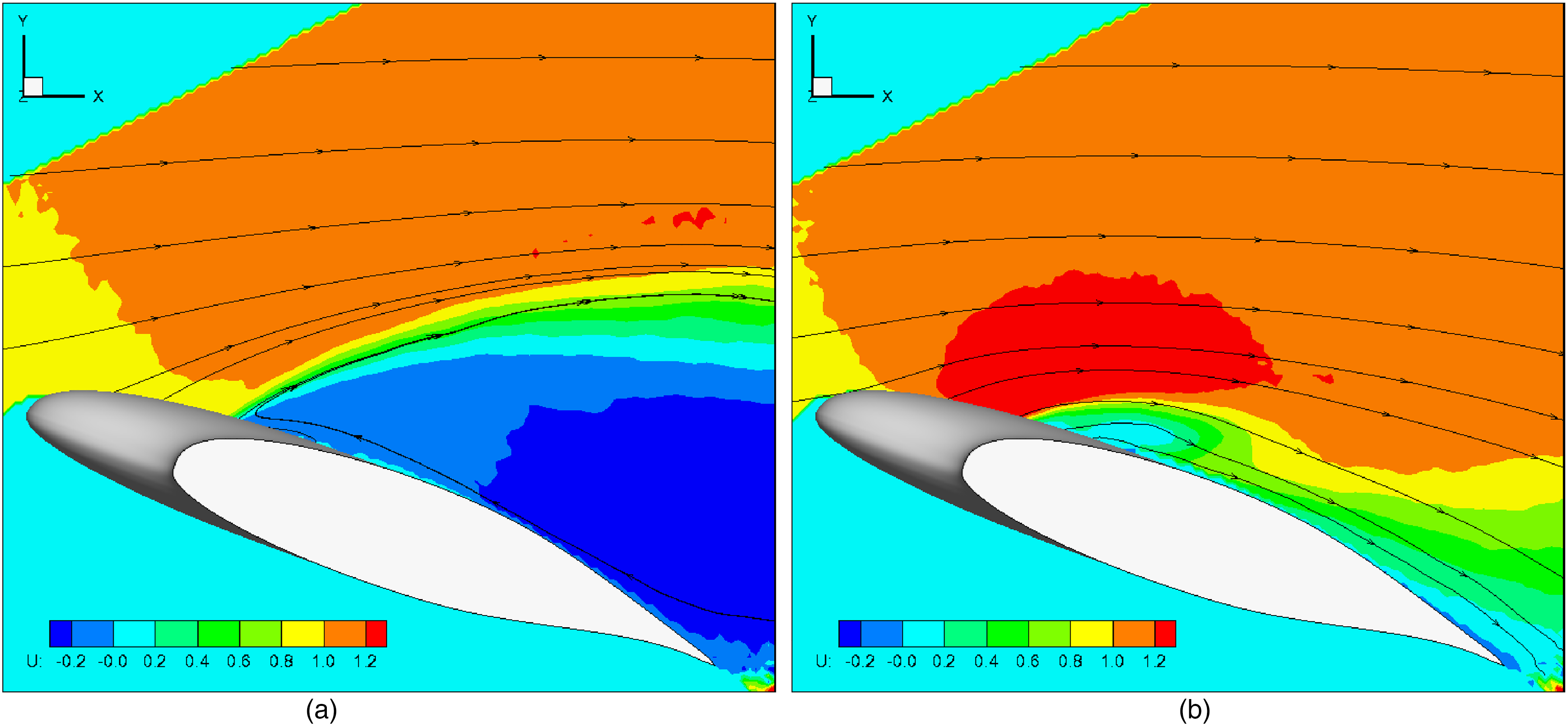
Time-averaged flow maps around the SLE wing from SPIV at z = 3/4c (trough section) and α = 20 degree, for AFC on with (a)
Numerical simulations were also carried out for the post-stall regime corresponding to α = 20 degrees, aiming to provide more complete views of the response of the flow around the SLE to the application of AFC in such circumstances. As introduced earlier in section 3, a different modeling approach was selected to deal with these operating conditions, thus switching from IDDES to DDES (with F2 as shielding function) in the hybrid RANS/LES simulations carried out for the post-stall regime. This is justified by the prospect of massively separated flow with AFC off or low (Cf. Figure 16(a)), or an early transition to turbulence in the boundary layers with AFC on (Cf. Figure 15), both conditions yielding large extensions of (separated and attached) turbulent flow over the wing. The results of these numerical simulations are presented in Figure 17, revealing the three-dimensional shape of the surfaces (in dark gray) encircling regions of time-averaged reversed streamwise velocity, for the cases of AFC off, and AFC on with
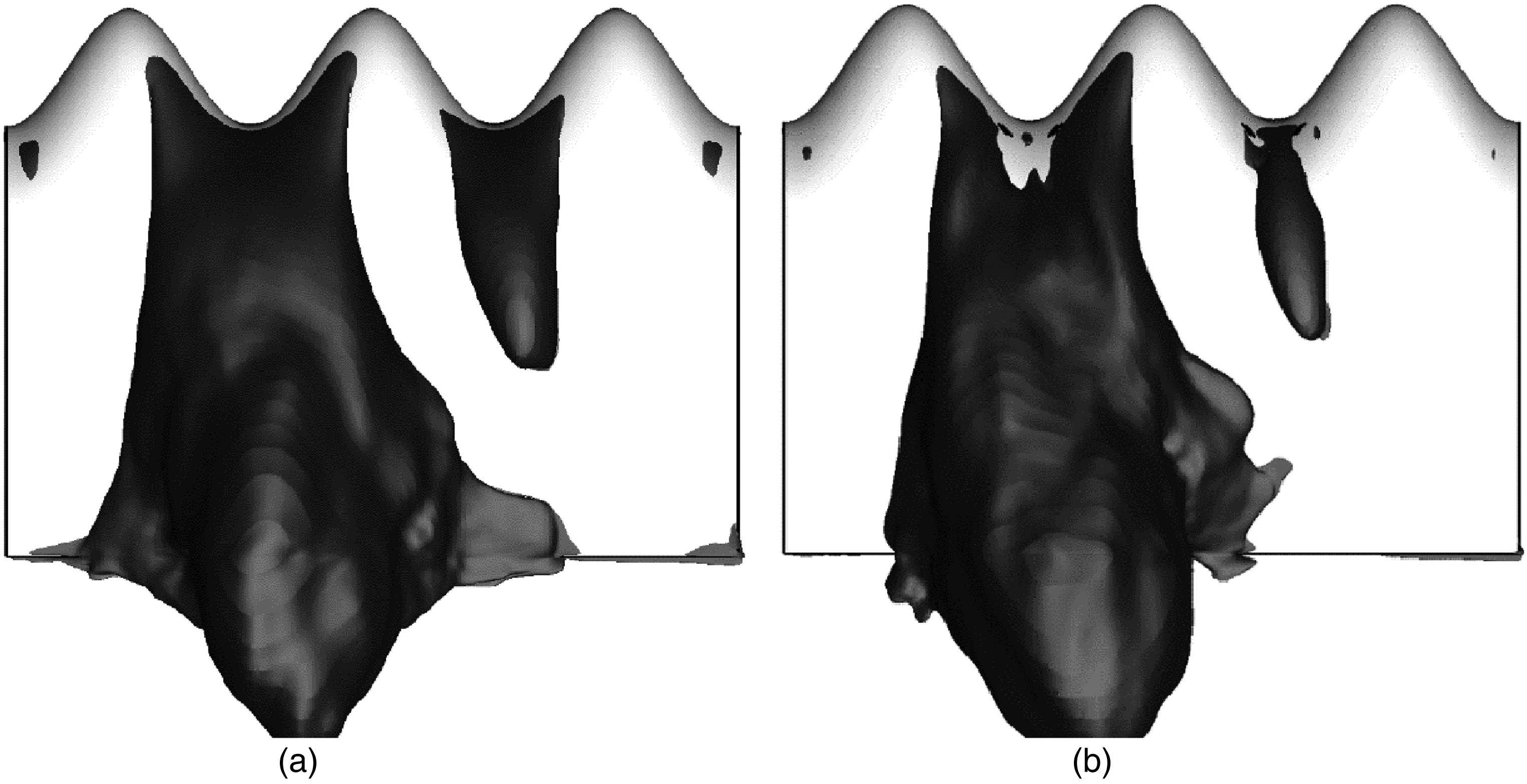
Computed regions of reversed time-averaged streamwise velocity (dark gray surface contours for zero streamwise velocity) over the SLE wing at α = 20 degree and
Effect of the injector diameter
In the previous sections, it was demonstrated that with the use of the AFC system the lift-generation performance of the SLE wing can be improved at both pre- and post-stall operating conditions, although such gains depend strongly on the micro-air jet characteristics. Initial tests were conducted employing injectors with a cross-sectional area
With a fixed cross-sectional area of the injectors, the variations in the jet velocity ratio were coupled with those in the volumetric flow coefficient (as well as with those in the momentum coefficient; Cf. Table 1). Aiming to optimize the AFC system for hybrid flow control, an additional degree of freedom is allowed by changing the aforementioned area. Whereas further increasing the diameter of the injectors may be problematic due to restrictions of space inside a MAV, a reduction in size emerges as a reasonable option. Based on available data, the setting

Lift enhancement by the AFC system versus angle of attack for two different injector diameters and
Facing a background of power constraints in MAV applications, as the AFC devices stand as major energy consumers, the amount of power required for their operation plays an important role in the design. Hence, as introduced earlier in this paper, the power coefficient
Conclusions
Experimental and numerical investigations of the lift-generation capabilities of a finite wing with a SLE were conducted at Re = 140,000, covering both pre- and post-stall operating conditions. As a first step, the strengths and weaknesses of the leading-edge modification as a passive stall control technique were identified employing SPIV images and DES simulations. Although significant lift gains can be obtained at post-stall with respect to the baseline wing, losses in lift are observed at pre-stall. In addition, earlier stall also occurs despite that the phenomenon itself becomes smoother. It was concluded that the main reason behind the foregoing deterioration in performance was the formation of a LSB in the troughs of the SLE wing, as a consequence of the local intensification of the suction peak.
Aiming to retrieve the lift characteristics exhibited by the baseline wing at pre-stall, an AFC system was designed, installed and assessed in a SLE wing prototype, so that the LSBs could be eliminated or at least minimized. The system was based on micro-air injection at the onset of the LSBs, operating with various values of the jet velocity ratio, and using two different injector diameters. Measurements of the lift coefficient with the larger injectors (
The effect of varying the injector diameter was also studied, so that the value of the jet velocity ratio could be decoupled from the flow rate coefficient. Measurements of the lift coefficient were carried out again, employing thinner injectors (
Footnotes
Acknowledgements
This work has been supported by Fundação para a Ciência e a Tecnologia (FCT), through IDMEC, under LAETA, project UIDB/50022/2020.
Declaration of conflicting interests
The authors declared no potential conflicts of interest with respect to the research, authorship, and/or publication of this article.
Funding
The authors disclosed receipt of the following financial support for the research, authorship, and/or publication of this article: This work was supported by the Fundação para a Ciência e a Tecnologia, (grant number UIDB/50022/2020).