
Abstract
Flapping wing deformation influences the aerodynamics of insect flight. This deformation is dictated by the dynamical properties of the insect wing, particularly its vibration spectra and mode shapes. However, researchers have not yet developed artificial insect wings with vibration spectra and mode shapes that are identical to their biological counterparts. The goal of the present work is to develop artificial insect wings that are both isospectral and isomodal with respect to real insect wings. To do so, we characterized hawkmoth Manduca sexta wings using experimental modal analyses. From these results, we created artificial wings using additive manufacturing and heat molding. Between artificial and real wings, the first two natural frequencies differ by 7% and 16% respectively, with differences of 16% and 131% in gains evaluated at those natural frequencies. Vibration modes are similar as well. This work provides a foundation for more advanced wing design moving forward.
Keywords
Introduction
Flapping wings are integral to the flight of small insects. Unlike conventional fixed wing or rotor-based aircraft, insects use unsteady aerodynamic forces to achieve flight at low Reynolds numbers. 1 At such length scales, flapping flight is believed to be more energetically efficient 2 and offer enhanced dexterity relative to other flight modalities. As a result, numerous centimeter and millimeter flapping wing micro air vehicles (FWMAVs) have been designed using insects as inspiration. 3 Such vehicles have been proposed for various tasks that necessitate the vehicle operate in densely congested spaces or undetected. Potential applications for FWMAVs include gas leak monitoring in piping networks, identification of diseased crops in agricultural settings, and military reconnaissance missions. Further, owing the low material cost, FWMAVs could also be deployed in swarms to provide atmospheric or other distributed measurements with high spatial density. However, many technical challenges, including inefficient energetics and unreliable onboard sensing, have inhibited FWMAV application. An improved understanding of the insect wing may provide meaningful insight into FWMAV wing design to help overcome such technical challenges.
As biological or engineered wings flap, they deform from both aerodynamic and inertial–elastic forces. 4 Wing flexibility is thought to enhance flight performance—deformation has been shown to increase aerodynamic force generation, 5 to reduce the inertial power requirements of flapping,6,7 and to influence aerodynamic power economy. 8 Further, wing deformation in some insects stimulates mechanoreceptors that provide the insect with the neurological feedback required to control attitude during flight. 9 The insect wing therefore behaves as an actuator and a sensor, and wing flexibility appears to be critical to both of these roles. As a result, many FWMAV researchers have exploited tuned compliance in their wings to realize some of the benefits associated with deformation. 10 The geometric and material properties of real insect wings, as well as their static and dynamic behavior, are often used as guidelines for these engineered wings.
A variety of techniques have been used to study the geometric and material properties of insect wings, including micro-computed tomography (CT), scanning electron microscopy, acoustic microscopy, and nanoindentation. Jongerius and Lentink used micro-CT scans of dragonfly wings to characterize vein geometry, to measure thickness distribution and to identify corrugation patterns. 11 Kreuz et al. used acoustic microscopy to investigate the intricate wax structure on dragonfly wings. 12 Song et al. measured the hardness and elastic modulus of cicada wings using nanoindentation, 13 while Talucdher and Shivakumar obtained the tensile modulus and strength of damselfly wing veins via tensile testing. 14 These studies have provided the foundation to better understand the macroscale mechanics of insect wings both under static and dynamic loading conditions.
Static tests are used predominately to determine how the stiffness of the insect wing varies spatially. Through a series of static force–displacement type tests, Combes and Daniel determined that hawkmoth Manduca sexta wings decrease in flexural rigidity from wing root to tip and that chordwise stiffness is an order of magnitude less than spanwise. 15 Ma et al. conducted similar experiments in honey bee Apis mellifera forewings and also observed the disparity between spanwise and chordwise stiffness. 16 More recently, Meresman et al. used force–displacement tests on scarab beetle wings and identified variations in local compliance between different species. 17 They conjectured that these stiffness variations arose in order to accommodate the varied lifestyle demands of the beetles considered.
In contrast to static tests, dynamic characterization aims to determine how the wing behaves under time-dependent loading. Ha et al. identified the wing fundamental frequencies for several insect species using a noncontact displacement sensor and concluded that these fundamental frequencies typically do not coincide with the insect’s wingbeat frequency. 18 Clark et al. measured the natural frequencies and vibration modes of honeybee wings using laser vibrometry and also concluded this species did not flap at their wing’s resonance. 19 Norris et al. conducted a similar experiment with M. sexta forewings in and out of vacuum and showed that added mass could reduce the first natural frequency of the wing about 30%. 20 Ha et al. demonstrated that digital image correlation could also be an effective noncontact means to estimate wing dynamical properties, however they used an artificial insect wing rather than a real one. 21
With abundant data available for real insect wings, many researchers have produced artificial bioinspired wings that, in some cases, mimic some of the structural characteristics of biological wings. Liu et al. produced an artificial cicada wing with biomimetic properties based on geometric and structural data including vein thickness, wing mass, and flexural stiffness profile. 22 DeLeón and Palazotto developed an artificial hawkmoth wing with similar mass, geometry and natural frequencies to its biological counterpart. 23 They compared the deformation of the artificial and real wings under large flapping conditions, and while they observed some similarities in the two responses, they found that the engineered wing deformed significantly more. Shang et al. established a technique to fabricate sophisticated centimeter-scale wings with carbon fiber venation and Polydimethylsiloxane (PDMS) membrane. 10 In each of these cases, the vein structure was made of laser-cut carbon fiber, however, cast molding and other Micro-Electro-Mechanical Systems (MEMS) based techniques have been used to realize vein structures as well.24,25 Membrane materials include kapton film, mylar, and PDMS, to name a few. In most cases, the membrane is attached to the vein structure using an adhesive, while materials such as PDMS can be molded and cured around the veins directly.
These studies and many more have significantly advanced the state-of-the-art in artificial wing design. However, to the best of our knowledge, no wing has been designed to be both isospectral and isomodal with respect to its biological counterpart. Isospectrality between a real and artificial wing implies that they have the same frequency response functions (FRFs). Isomodality implies that the two wings have identical vibration mode shapes. If artificial and real wings are both isospectral and isomodal, they will deform similarly while flapping in vacuum, at least when the wing behaves within the linear structural range. Even under conditions in which the wing deforms nonlinearly, linear isospectrality and isomodality provide a good basis for wing design that can be expanded upon moving forward. Aerodynamic effects may cause differences in deformation even if wings are isospectral and isomodal; however, these differences are expected to be small if the wings have identical geometry.
The objective of the present research is to design artificial insect wings that are isospectral and isomodal with respect to real insect wings. Successful realization of such artificial wings can significantly improve our understanding of biological flapping wing. Experiments which use real insect wings are time-sensitive since the wings desiccate and change in material property after being removed from the insect’s body. In contrast, the artificial wing’s properties are stable, which makes them more suitable for experiments that take place over longer time periods. Further, this research informs wing design for FWMAVs and demonstrates how certain morphological parameters affect the wing’s dynamic response. This research can be combined with flapping fluid-structure interaction (FSI) models or physical experiments to better predict the aerodynamic performance of flexible wing’s during flight. For this work, we focus on matching dynamic characteristics only through the wing’s first two vibration modes; we do not consider higher order vibration modes.
The remainder of this paper is organized as follows. First, we present the modal analysis procedure used to dynamically characterize hawkmoth M. sexta forewings. Next, we establish a finite element (FE) model to help guide artificial wing design, and discuss the manufacturing process utilized to fabricate the artificial wings. We then characterize the artificial wings using the same modal analysis procedure as was used for the real wings and compare findings. We conclude by discussing some of the implications and future directions of this research.
Dynamic characterization of insect wings
We use modal analysis to characterize the FRFs and vibration mode shapes of hawkmoth M. sexta forewings. M. sexta are among the most well-studied flying insects (Figure 1). We recognize that several researchers have employed similar techniques to dynamically characterize insect wings, in particular Norris et al., who found FRFs and mode shapes for the same insect we are studying. 20 Thus, wing characterization is not the principle contribution of this work, though it is necessary to determine a suitable set of FRFs and mode shapes to design artificial wings from. Conducting our own modal analysis also ensures consistent experimental conditions between real and artificial wing characterizations.

Hawkmoth M. sexta with forewings splayed. Each grid box is 0.5 mm × 0.5 mm.
Insect preparation and wing morphology
Tobacco hornworm (M. sexta) larvae were shipped to Montana State University from Josh’s Frogs (Owosso, MI, USA). Upon arrival, larvae were relocated to a climate-controlled rearing room at a temperature of 28 ± 2°C. Larvae remained in a 24:0 (L:D) h photoperiod to restrict photoperiodically induced pupal diapause. 26 The larvae developed in 0.95 L insect cups with perforated lids and were sustained by Repashy Superfoods Superhorn Hornworm Gutload Diet from Repashy Ventures in Oceanside, CA. Gutterscreen was placed into the cups to provide the larvae a climbing surface.
Each cup contained three to six larvae. Larvae were visually inspected for overall health and waste was removed daily. These conditions were maintained for approximately 14–21 days while larvae developed prominent aortae. Once the larvae discontinued feeding, they were relocated to a large Sterilite latching box (23 cm L × 38 cm W × 28 cm H) filled with a uniform 5 cm layer of lightly moist peat soil. Within 48 h the larvae pupated, and adults emerged after two to three weeks. The wings of freshly emerged adults were allowed to fully develop before sacrifice. The moths used in this study were mixed gender, with no intentional bias toward either gender. Before testing, moths were euthanized via a 3.78 L kill jar containing ethyl acetate in a base of Plaster of Paris, in which they remained for 15 min until death. To initiate testing, one hawkmoth forewing was removed from the euthanized moth’s body at the wing root using dissection scissors. The remaining wing was left attached to the moth and placed in a refrigerator for the duration of the removed wing’s testing, which lasted maximally 1 h. We tested eight wings in total between four months.
Lastly, before to modal testing, we photographed wings on a gridded mat. Photographs were imported into ImageJ for postprocessing. 27 From the images, we estimated the wing’s span, surface area, and maximum chord width (Figure 5). We subsequently weighed all wings using a Mettler Toledo XS 205 scale to determine their mass. Morphological parameters for all insects tested are summarized in Table 1. These parameters serve as guidelines for artificial wing design.
Hawkmoth M. sexta forewing morphological properties.

Modal testing
We used base excitation via an electrodynamic shaker to excite the wing and measured the wing’s response using a planar scanning laser Doppler vibrometer (Figure 2). Excised forewings were loaded into a custom-made clamp that holds the wing in place at the root, creating a clamped-free boundary condition. Two strips of 3.2 mm hobby foam were placed on either side of the wing in the clamp to preserve the wing’s natural camber, and approximately 3.2 mm of the wing at the root was inserted into the clamp (Figure 3). It is important to maintain the wing’s natural camber because camber increases stiffness in some structures. 28 The wing/clamp assembly was loaded into a 31 N electrodynamic shaker (The Modal Shop, K2007E007). A swept sine periodic chirp signal ranging from 10 to 1000 Hz was applied via an amplifier attached to a signal generator. Data were acquired at 2.56 kHz, which produces a spectral resolution of 3200 FFT lines over the frequency range. A planar scanning laser vibrometer (Polytec, PSV 400) was used to produce a full scan of the wing during excitation. An accelerometer (PCB Piezotronics, 352A21) was affixed to the clamp using mounting wax and was used as a reference channel. These data were processed from the time domain to frequency domain via fast Fourier transformation within the Polytec PSV software. The resulting FRF relates base acceleration to wing velocity. Across all wing’s tested, the maximum deflection was about 2 µm. Doubling the base acceleration doubled the wing’s maximum deflection, which strongly suggests all tests occurred within the linear-elastic regime.
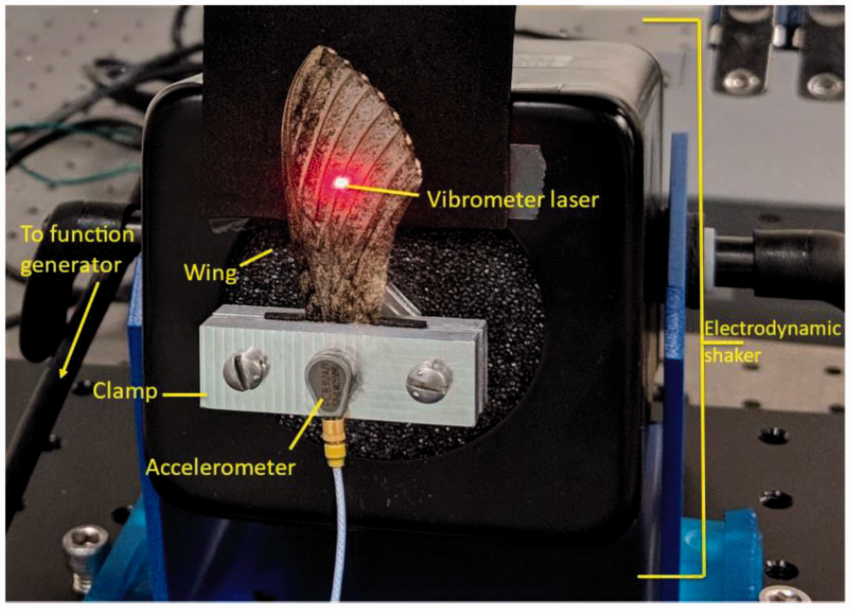
Experimental setup used for modal characterization of artificial and real insect wings.
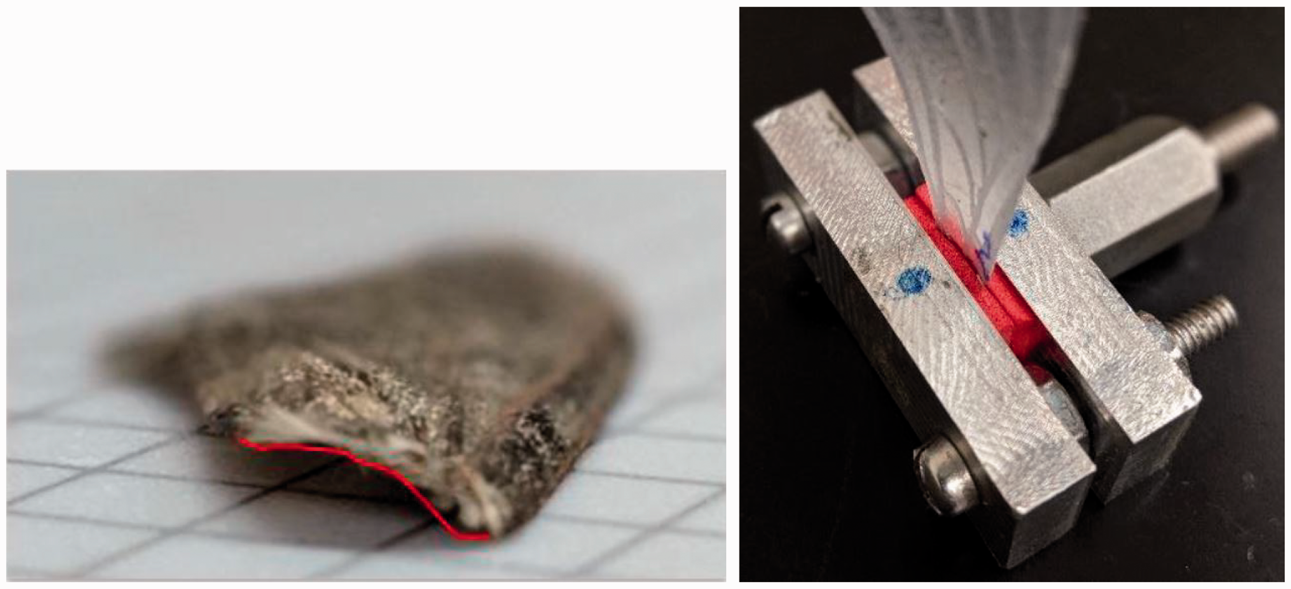
(Left) Camber at wing base traced in red and (Right) wing clamp with hobby foam to maintain wing base camber during modal testing.
Spatially averaged FRFs were processed in PSV software to determine the wing’s first two natural frequencies ωn and damping ratios ζn. Mode shapes were reported directly from the PSV software. Note that all mode shape comparisons were purely qualitative; quantitative comparison is challenging due to varying sizes between biological samples. We also determined FRF gain
Modal testing results are summarized in Table 2. The first two natural frequencies, which occur at 69.1 Hz and 95.5 Hz respectively, agree reasonably well with the 60 Hz and 84 Hz natural frequencies reported by Norris et al. 20 The increased higher natural frequency values reported here may stem from improved camber retention of the wing clamp, or from natural variation in wing mass and length. Damping ratios and mode shapes are also in agreement with previous literature, where the first vibration mode corresponds to a bending mode and the second corresponds to a torsional or twisting mode (Figure 4). Given the 25 Hz flap frequency of the M. sexta, 29 it is likely that both of these vibrational modes are excited during flight, particularly given that multidimensional flapping gives rise to dynamic excitation at harmonics of the wing’s flapping frequency. 30 The gain at the first natural frequency is approximately 3.5 times greater than that at the second natural frequency. This does not necessarily imply that the wing will bend more than twist, but does suggest excitation around the first natural frequency will be amplified more than excitation around the second.
Hawmoth Manduca sexta forewing dynamical properties.


First two vibration modes of the M. sexta forewing, where the first mode (left) corresponds to bending and the second mode (right) corresponds to twisting. Red denotes displacement in +z, blue denotes displacement –z, and green indicates no displacement. The color map is in units (mm/s)/(mm/s2), which is the velocity of the wing measured at multiple points via the vibrometer normalized to measured base acceleration. The modal displacement is directly proportional to the velocity and depends on the specific base acceleration.
Note that all modal testing was conducted in air. As a result, added mass and aerodynamic loading affect the wing’s natural frequencies. Added mass tends to reduce the wing’s natural frequencies, since the vibrating wing must an accelerate the air mass surrounding it. Previous literature suggests added mass does not affect the mode shapes themselves. 20 Aerodynamic loading acts as a direct excitation term similar to the inertial excitation induced by the electromagnetic shaker. This aerodynamic loading influences the gain of the frequency response curve, and based on prior research, likely the effective damping. 31 These experiments could be repeated in vacuum to compare the wing’s structural characteristics absent aerodynamics; however, we believe it is necessary to compare wings within their normal operating medium.
Design and fabrication of artificial wings
The dynamic and morphological characteristics of the M. sexta wings serve as target parameters for the isomodal–isospectral artificial wings. To inform the design, we created an FE model of the wing keeping in mind available manufacturing methods. Once the wing has been modeled, we detail the design process which leverages 3D printing and heat molding.
FE modeling of artificial wing
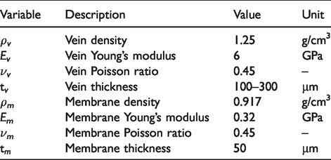
We developed an FE model of the artificial wing using ABAQUS (Figure 5). This model provides a numerical tool to iterate on artificial wing designs. It consists of two parts: a vein scaffolding and a membrane structure stretched between the vein. In general, venation provides the bulk of the structure while the membrane is necessary for aerodynamic force generation. Material properties for both parts are summarized in Table 3.

FE model of M. sexta forewing. Cross-hatching denotes the boundary condition region where all degrees of freedom are constrained to zero.
Material properties for artificial wing finite element model.
We modeled the general vein structure roughly based on micro-CT images available from Norris. 32 Individual veins have rectangular cross sections with thicknesses ranging from 100 to 300 µm, which falls within the 30–500 µm vein diameter range observed in M. sexta. 33 The thickness variation is intended to approximately follow the mass distribution determined through previous work. 6 We attempted multiple thickness variations along this general distribution, and within manufacturing constraints, arrived at the configuration shown in Figure 8. Note that the vein component along the perimeter of the trailing edge does not exist in real insects; this structure was required in artificial wing design to provide a structure to adhere to the membrane. The membrane has a uniform thickness of 10 µm and is overlaid on the vein structure. The membrane and vein parts are restricted to move together using tie constraints. In total, the membrane and vein are discretized into approximately 4200 and 1900 shell elements respectively, which was sufficient for convergence of at least the structure’s first two natural frequencies. The wing model is curved to roughly match the profile reported in O’Hara and Palazotto. 33 To emulate experimental boundary conditions, all degrees of freedom within 3.2 mm of the wing base were fixed such that they experience no translation or rotation (Figure 5). We then conducted a numerical modal analysis using a block Lanczos eigensolver to calculate the first two natural frequencies and mode shapes of the wing. We did not compute vibration spectra via finite element analysis (FEA). The FE model predicted the artificial wing’s natural frequencies as 67.7 Hz and 115.5 Hz for the first two modes respectively, compared to the biological averages of 69.1 Hz and 95.5 Hz. The FE model estimated the first mode as a bending mode and the second as a torsional mode (Figure 6), which are consistent with the mode types observed in the biological wing (Figure 4).
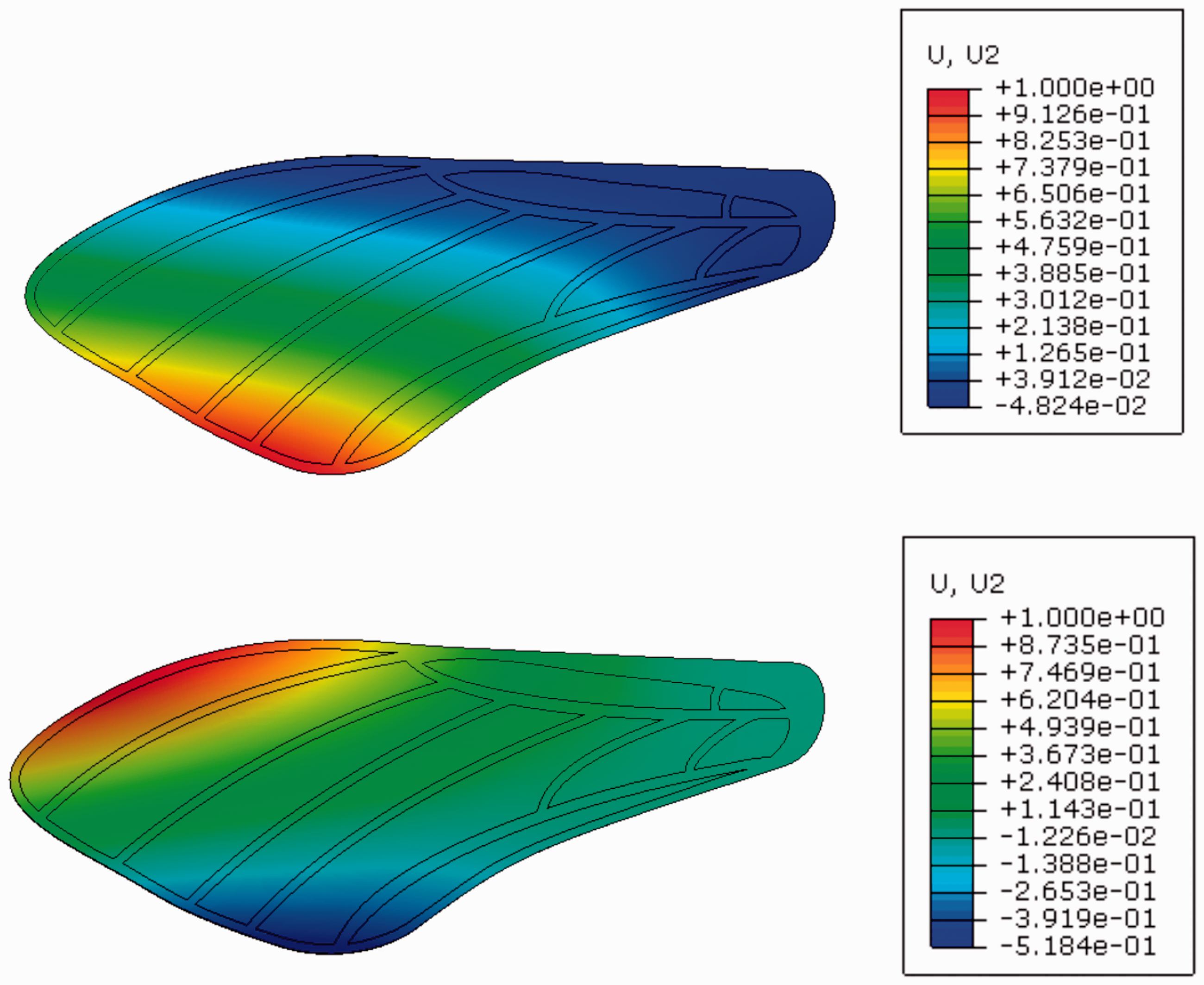
Vibration modes of the artificial wing calculated via finite element analysis. (Top) First vibration mode, bending and (Bottom) Second vibration mode, torsion.
Wing fabrication
Figure 7 illustrates the manufacturing process of artificial wings. First, we designed the vein structure of artificial wings based on collected data from biological wings. We designed the vein structure with 47.6 mm span and 18 mm max chord width based on the average size of biological wings. Our design has varying thicknesses based upon the mass distribution determined through previous cut-and-weigh experiments. 6 We employed varying thickness near the root such that the main vein structure is 0.10 mm, the middle vein structure near the root and leading edge is 0.20 mm, and the thickest part at the root is 0.30 mm, as shown in Figure 8. Notably, the designed vein structures needed to be 3D printable, which means all of the designed veins must be slightly wider than the printer nozzle size. Second, we printed the vein structure by fused filament fabrication (FFF), an additive manufacturing process, using a desktop 3D printer (Original Prusa i3 MK3S, Prusa Research a.s., Prague, Czech Republic). The vein material was polylactic acid (PLA). We obtained 3D printed flat three-layer vein structures by this step. Third, we applied a membrane to the vein structure. We manually covered and pressed a thin polymer film (Press’n Seal, The Glad Products Company, Oakland, CA), which emulates the wing membrane, on the smooth side of the 3D printed vein structure. The film attached to the vein structure firmly by manually applying press on the film. We then trimmed the film along the vein structure boundary to get a flat artificial wing. Fourth, we curved the flat artificial wing in a 3D printed mold. To match the curvature of the real wings, we designed the mold based on the curvature of real wings and 3D printed the mold by the same 3D printer using acrylonitrile butadiene styrene (ABS) material. The curvature of artificial wings was generated after placing them in the molds and applying heated air of 100°C through the bottom channel for 3 min. Lastly, we cooled the wing in air and removed the finished artificial wings from the mold.

Manufacturing process of the artificial wings.

Simplified layup of additive-manufactured artificial wing.
Comparison of biological and artificial wings
Finally, we compared the M. sexta forewings to the newly fabricated artificial wings. Morphological and dynamic characteristics are summarized in Table 4, and an indicative FRF comparison is shown in Figure 9. Vibration mode shapes are shown in Figure 10. In general, the morphological parameters agree fairly well. The wings are similar in surface area, span, and chord and mass (Table 4). The manufacturing process was repeatable in terms of creating a planar geometry; however, there was a mass variation in artificial wings comparable to that observed in real wings. This likely has to do with the tolerances permitted by the vein print process, as fluctuations in weight can arise from inconsistent layer height. The artificial wings are slightly heavier than the real wing despite having lesser surface area; however, we were unable to reduce mass while maintaining dynamic stiffness without exaggerating the wing’s curvature by an unrealistic amount. Mass reductions with the current design likely necessitate the vein scaffolding be made of a different material.
Comparison between the morphological and dynamic characteristics of artificial and real insect wings.

Averages and standard deviations are for eight samples of each wing type.

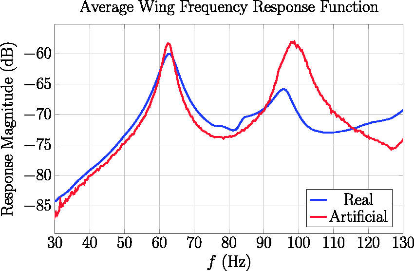
Comparison of spatially averaged frequency response functions for artificial and real insect wings.
Comparison of the first and second mode shapes for artificial and real insect wings. Note that a mode shape is the pattern of deflection the wing follows when excited at a particular natural frequency.
Next, we consider the wing’s dynamic characteristics (Table 4). Both the first natural frequency and the gain at this natural frequency agreed well between the two wings. The increased gain for the artificial wing may be attributed to lower damping. The first mode shapes, while having similar qualitative features, were more disparate (Figure 10). For the biological wing, the first mode shape was a true bending mode, where the modal displacement is largest near the wing tip. The first mode shape of the artificial wing was primarily bending; however, the predominant displacement occurred near the trailing edge. Further, while the displacement at the trailing edge was positive, there was slight negative deflection near the leading edge, which is indicative of torsion. The difference between the wing’s second natural frequencies was larger, though the standard interval between the two overlaps. The artificial wing was consistently stiffer than the real wing against torsional deformation. More notably, the artificial wing’s gain was much higher, which suggests it would twist more during normal flapping. At the second mode shape (Figure 10), the artificial wing experiences significant deflection at the leading edge. By contrast, the real wing is largely stationary along the leading edge and experiences maximum deflection near its tip. The trailing edge displacements are similar for both real and artificial wings. We discuss potential sources of these natural frequency and mode shape discrepancies in the following Discussion section.
Discussion
In this work, we developed a process to fabricate artificial insect wings that are dynamically similar with respect to their biological counterparts. Specifically, the artificial wings were intended to be isospectral and isomodal with respect to real insect wings, which implies the two have identical FRFs and vibration mode shapes. To inform the design of artificial wings, we characterized the morphology and dynamical properties of hawkmoth M. sexta forewings using image-based techniques and experimental modal analysis. We then designed the artificial wings using FE analysis and subsequently fabricated them using a 3D printing process in conjunction with heat-treated molding. Lastly, we characterized the artificial wings also using experimental modal analysis. We found that artificial and real wings had similar morphological parameters. Their first natural frequencies and gains evaluated at that natural frequency are very similar; however, the second natural frequency had a larger disparity. The vibration mode shapes had similar characteristics, though the exact location of deformation deviated between the real and artificial wings. The following discussion focuses on how the fabrication process can be further improved to minimize differences between artificial and real wings, as well as dynamical features we identified in insect wings that should be incorporated in further iterations of wing design.
Improvements on wing design
Overall, the artificial wing design process is an improvement over existing techniques. Unlike conventional fabrication processes that utilize laser cut carbon fiber,10,23 our process uses primarily additive manufacturing. 3D printing has become an increasingly inexpensive technology that is available to many laboratories. In contrast, the methods required to cut carbon fiber are more sophisticated. Further, the press-and-seal membrane is simpler and provides a good alternative to PDMS molds or kapton films employed by other designs. At the same time, our manufacturing process produces satisfactory results in terms of producing an artificial wing that has a similar dynamic response with respect to the actual insect wing. Thus, one of the principle benefits of the present research is a manufacturing process that is accessible to other flapping wing researchers, either for controlled studies of flapping wings or for inclusion on centimeter-scale FWMAV designs.
However, this work also highlights some of the limitations of 3D printing on wing fabrication. Most notably, we were unable to achieve the vein and thickness variation observed in real insect wings due to print tolerance restrictions. This adversely affected the artificial wing’s vibration mode shapes, as well as the gain evaluated at the second natural frequency. Consider Figure 10. The artificial wing had the largest displacement at the trailing edge, whereas the real wing had the largest displacement at the wing tip. The mass distribution of the real wing typically tapers from the leading to trailing edge, which implies most mass is distributed toward the leading edge vein. In contrast, the artificial wing had similar mass distribution along the chord. If we were able to further reduce the thickness and mass of the trailing edge, the maximum deflection of the first vibration mode would begin to shift toward the wingtip, similar to what is observed in the real insect wing. The inability to modulate vein width influences the second mode shape as well. Whereas the largest displacement occurred near the trailing edge of the real wing, the largest displacement occurred at the leading edge of the artificial wing. If we were able to reduce vein width on the artificial wing, we would be able to reduce stiffness in this dimension which in turn promotes larger displacement near the trailing edge.
In addition to geometric restrictions, material restrictions may also contribute to discrepancies between real and artificial wings. Real insect veins are composed of chitinous cuticle which can be viewed as a biological composite. Much of the cuticle is sclerotized to provide rigidity and structural support to the wing. Research shows that the modulus of the cuticle varies through its thickness to create a stiffness gradient. Additionally, some insect wings are embedded with resilin, 5 a rubber-like protein that promotes wing deformation during flight. 34 Both spatial variation of material type as well as gradation within a single material contribute to the structural dynamics of the wing. However, these features would be challenging to incorporate into an artificial wing even with sophisticated 3D printers.
In summary, the wing fabrication process would benefit from a 3D printer with better resolution, both in the X–Y plane as well as through the thickness. If additional resolution was available, we could further improve the design by using FE topology optimization, an automated technique intended to adjust the morphology of a structure to agree with a prescribed set of natural frequencies and vibration modes. Moreover, the ability print a structure in multiple materials, or grade the properties of a single material, would further enhance our authority to manipulate the wing’s dynamic properties. Nonetheless, the initial efforts described in this paper provide a suitable initial wing design and provide the framework for more advanced studies.
Observations in insect wings
Throughout our experimental modal analyses on M. sexta wings, we encountered some dynamic features not reported by previous studies. While replicating these features on the artificial wings designed was out of the scope of the present study, these are interesting characteristics that should be given consideration in wing design moving forward. Most notably, we determined that the phase relationship between points on the second vibration mode (Figure 10) is not stationary. This implies that the second vibration mode of the insect wing is a complex mode rather than a normal mode. Complex modes arise when damping is nonuniform throughout a structure, and implies that there is a region in which energy is dissipated more rapidly. To the best of our knowledge, complex modes have not been previously reported for M. sexta. Because the complex mode corresponds to torsion, it likely affects the wing’s angle of attack and consequently the wing’s aerodynamics. Substantially more effort must be invested to fully understand if localized damping and the complex vibration modes that come with it affect an insect’s flight performance.
Second, we found that M. sexta wings exhibit vibration mode coupling if base accelerations are sufficiently high. This implies that with large excitation, the wings exhibit nonlinearity. In linear systems, if a structure is excited at a singular natural frequency, the response of that structure will only show characteristics of the corresponding vibration mode. In nonlinear systems, there may be energy exchange between vibration modes. This implies that, even if the wing is excited at a natural frequency that corresponds to a bending mode, there may be some torsional response due to modal coupling. Given the large flapping during normal flight, it is likely that modal coupling plays a role. Modal coupling may arise from a number of factors, including structural nonlinearity from the camber of the wing, or from state-dependent aerodynamic loads that are influenced by the wing’s deformation. Like localized damping, modal coupling is a topic the requires extensive exploration to identify if and how it influences biological flight.
Footnotes
Declaration of conflicting interests
The author(s) declared no potential conflicts of interest with respect to the research, authorship, and/or publication of this article.
Funding
The author(s) disclosed receipt of the following financial support for the research, authorship, and/or publication of this article: This material is based upon work supported by the National Science Foundation (NSF) Grant Nos. CBET-1855383 and CMMI-1942810 to M.J. This work is also supported in part by the startup funds from Binghamton University, and by the Small Scale Systems Integration and Packaging (S3IP) Centre of Excellence, funded by New York Empire State Development’s Division of Science, Technology and Innovation. Any opinions, findings, and conclusions or recommendations expressed in this material are those of the author(s) and do not necessarily reflect the views of the NSF.