
Abstract
This paper presents the design details and flight tests validation of printed circuit board fabricated micro gliders. The purpose of the micro glider is to be launched from a super pressure balloon at high altitude, glide to the target position to collect data and upload data to the staying balloon. The mission demand requires the micro glider to finish precise landing with small size and low fabrication cost. To complete this concept, we designed a PCB fabricated aircraft with limited sensors including GPS and IMU. The first part of the article describes the aerodynamic design methods. The second part introduced the control and guidance system design by controlling the roll angle and flight path angle to complete the precise landing. In the simulation results presented in the third part, launch with no wind condition shows desirable precise landing ability. As a contrast, wind direction and magnitude have significant effects on the guidance ability and accuracy. In the last part, two real flight tests conducted in Inner Mongolia of China are described to compare the flight performance with the current aerodynamics and control system design. Returned data indicated the micro gliders could successfully fly at high altitude. The control algorithm can compute the command roll angle only with GPS and IMU, but some design details still need to be improved to achieve precise landing ability.
Introduction
High altitude balloon platforms, including zero-pressure and super-pressure balloon, have been widely used for launching large-size aircraft models from high altitude for validating their aerodynamic performance.1,2 By comparison, the way of launching small-size aircraft models is more flexible, which could be implemented by small size zero pressure balloons or weather balloons. In 2011, a US team launched SkyWisp glider from a weather balloon at 18 km altitude to measure and collect trace gases. Their experiment showed an excellent result that weather balloon could be a reliable platform for launching the aircraft from the high altitude. 3 In 2012, a Swiss group launched a new shape flying wing gilder Smartfish from a weather balloon at 32,000 m for validating the aerodynamic design for the possibility of flying in the Venus atmosphere. 4 In 2015, the group of Flying Robots in DLR launched a 3 m wingspan glider from near space by medium zero-pressure balloon and it landed precisely to the preprogrammed position by taking 45 min. 5 In 2018, an unmanned glider HiDRON was launched from 25 km altitude by a US group to validate weather model. The glider successfully flew back to the balloon launching position. 6 These flight campaigns showed the feasibility for the small or medium aircraft to be launched by small-sized balloons to fly at high altitudes. As for micro-sized aircraft, although it has developed for over 20 years and a significant number of famous designs with various possible applications, such as surveillance and data collection, have been deeply studied, 7 the flight tests of micro air vehicles at high altitude are not well investigated. Present MAVs are designed for near-ground flight due to the short endurance and distance caused by limited energy storage. The latest MAV high altitude launch and flight were conducted by a Poland team to study the MAV flight performance in the stratosphere for the possible application in data measurement. 8 In 2012, NRL firstly proposed a new concept application for MAVs, which was called close-in covert autonomous disposable aircraft (CICADA). In their design, the propulsion system was removed to save energy for the mission sensor. The prototype of the CICADA with the integrated sensors had been launched from a mother glider Tempest at 9000 m for stabilizing the initial attitude. The purpose of the test was to validate the aircraft design and the feasibility of the control and navigation algorithm.9 The continuous experiments for CICADA conducted by balloon, fixed-wing model aircraft and Blackhawk helicopter were over 200 times. 10 On the other hand, progress of high altitude aircraft drop tests may be attributed to the development in balloon technology. In recent years, Google X lab proposed famous Loon project by applying super-pressure balloon to provide a wireless network to remote areas. 11 The balloons fly at quasi-zero wind layer at 20 km altitude and can control the trajectory depending on the inner balloonet and accurate wind field prediction. The last continuous flight record of Project Loon is more than 180 days. The ingenious initiative for the balloon application promotes the new development of balloon technology and also, from our opinion, it provides a new potential aircraft launching platform.
For expanding the potential application of MAVs, our group proposed a new application mode by taking the advantages of the gliding micro air vehicle proposed by NRL and the controllable super-pressure balloon platform proposed by Google as a long-endurance, long-distance launching and data collecting system. In our concept design, except the basic energy cycle and flight control system, the balloon system should also include a gondola for carrying a great number of micro gliders and a small-sized communication base for transferring data received from micro gliders to satellites. Energy supply for the balloon and micro gliders in flight is supported by the solar panels carried by gondola. After the balloon flying to the nearby region around the target waypoint, the gliders will be launched from the balloon and autonomously glide to the target position. Then the balloon will be controlled by the balloonet to stay within a specific range above the target waypoint to receive and transfer data. The application concept of the balloon and micro gliders system is shown in Figure 1. The innovative application of the balloon system and micro air vehicles proposed by our group provides a possibility for the MAV to execute long-endurance long-distance scientific or military missions. On the demand of missions, the micro glider requires precise landing, data collecting and transmitting ability with low cost. Present successful flights in the stratosphere are achieved by small and medium-sized aircrafts. The launch altitude of micro-sized CICADA is not high enough compared with the stratosphere. For high altitude launched from 20 km, MAVs may show a different performance caused by the low Reynolds number effects and worse wind resistance ability due to lightweight and small size. Further, long-distance guidance flight and precise landing with limited sensors are other challenges for MAVs. In our study, because the print circuit board wing will result in poor aerodynamic performance, the primary purpose is to validate the feasibility of transition from initial launch to equilibrium flight at high altitude. The second purpose is to validate wind resistance performance with the current design at strong wind zone around 10 km altitude. The last purpose is to verify the effectiveness of the control and guidance algorithm depending on limited sensors for further developments.

Concept of the super-pressure balloon launching platform system.
Micro glider design and fabrication
The conceptual design of the micro glider requires the structure must be simple and compact enough so that it could be carried in large quantities by a balloon gondola. Further, the cost of each micro glider should be as low as possible for the demand of mass manufacturing. Enlightened by the project of CICADA, we selected printed circuit board (PCB) as the glider wing material due to low-cost easy-fabricated characteristics. Further, flying wing configuration is adopted to design our micro glider as the advantage of decreasing wing load for small and compact aircraft. Maximum wing load criteria is limited lower than 50 N/m2, which follows the general criteria given by the present good performance fixed-wing micro air vehicles. 12 Based on mission demands, the micro glider should provide a large flight distance with compact structure. In aerodynamic design of the micro glider, we consider maximum flight range as one of the critical indicators to evaluate flight performance, which is estimated by the general translation motion equation without considering rotation motion around the point of mass. 2
Aircraft design
Wing planform design
Since PCB cross-section is a flat-plate airfoil, wind tunnel results for the various planforms of the flat-plate airfoil in low Reynolds numbers are referred as the research foundation for the wing planform design and numerical calculation.13–15 As can be concluded from wind tunnel results, inverse Zimmerman planform shows the best L/D ratio with the same aspect ratio. Therefore, inverse Zimmerman planform is adopted as the planform of our micro glider main wing. Moreover, three aspect ratios AR = 1, 2 and 4 under the constant wing area S = 0.04 m2 (wingspan length s = 24, 32 and 46 cm respectively) and one larger wing area with AR = 2 (S = 0.062 m2, s = 40 cm) are computed by the panel method. As can be seen in Figure 2, lift and drag coefficients agree well with experimental data at small α, which validates the feasibility by applying the panel method. For the constant S = 0.04 m2, AR = 4 shows the highest L/D ratio of 10, which is 25% and 66% higher than AR = 2 and AR = 1, respectively. However, AR = 4 may not be suitable to match the compact structure demand. On the other hand, the general flight range of AR = 2 is only 25% lower compared to the flight range with AR = 4, which is acceptable compared to the advantage of compact structure. For the longer wingspan of s = 40 cm (S = 0.062 m2) at AR = 2, the CL and CD show the same performance compared with s = 32 cm. The weight of the wing of s = 40 cm increases to 95 g but the wing load decreases to a better value of 34 N/m2. The calculation shows that the maximum flight range of the enlarged wing has the same performance of 160 km compared with small wing areas. It validates the conclusion that the flight range is only decided by L/D ratio. 16 As concluded, although larger aspect ratio or larger wing area shows better L/D ratio or wing load performance, the flight range still fails to perform a more significant enhancement than the more compact and smaller size of S = 0.04 m2 (AR = 2).

Aerodynamic performance computed by panel results. (a) Lift coefficient. (b) Drag coefficient. (c) Lift-to-drag ratio. (d) Pitch moment coefficient.
Elevons dimension design
Control of the micro glider flight is achieved by a pair of elevons. To maintain an acceptable L/D ratio while elevons deflect and further, to satisfy the full servo stroke demands while elevons deflect to limited angle, empirically the maximum elevon deflection angle should be smaller than 20°.
17
On the other hand, for trimming pitch movement Cm of the flat-plate airfoil, the elevons need to maintain an up-deflection angle in flight, which expressed as
Elevons calculations in panel method. (a) 10% local chord length with
Aerodynamic coefficients
As described in “Elevons dimension design” section, a counterweight is needed to trim the CG and thus the wing leading edge is modified by adding a small area for mounting the counterweight. Further, to calculate the aerodynamic coefficients of the full glider body, including fuselage and elevons, we adopted CFD method to achieve more precise results. Turbulence model of k-ω SST with low Reynolds number correction is used for closure RANS as it has been widely used for predicting micro air vehicles separation flow.
18
The grids number of the numerical model is
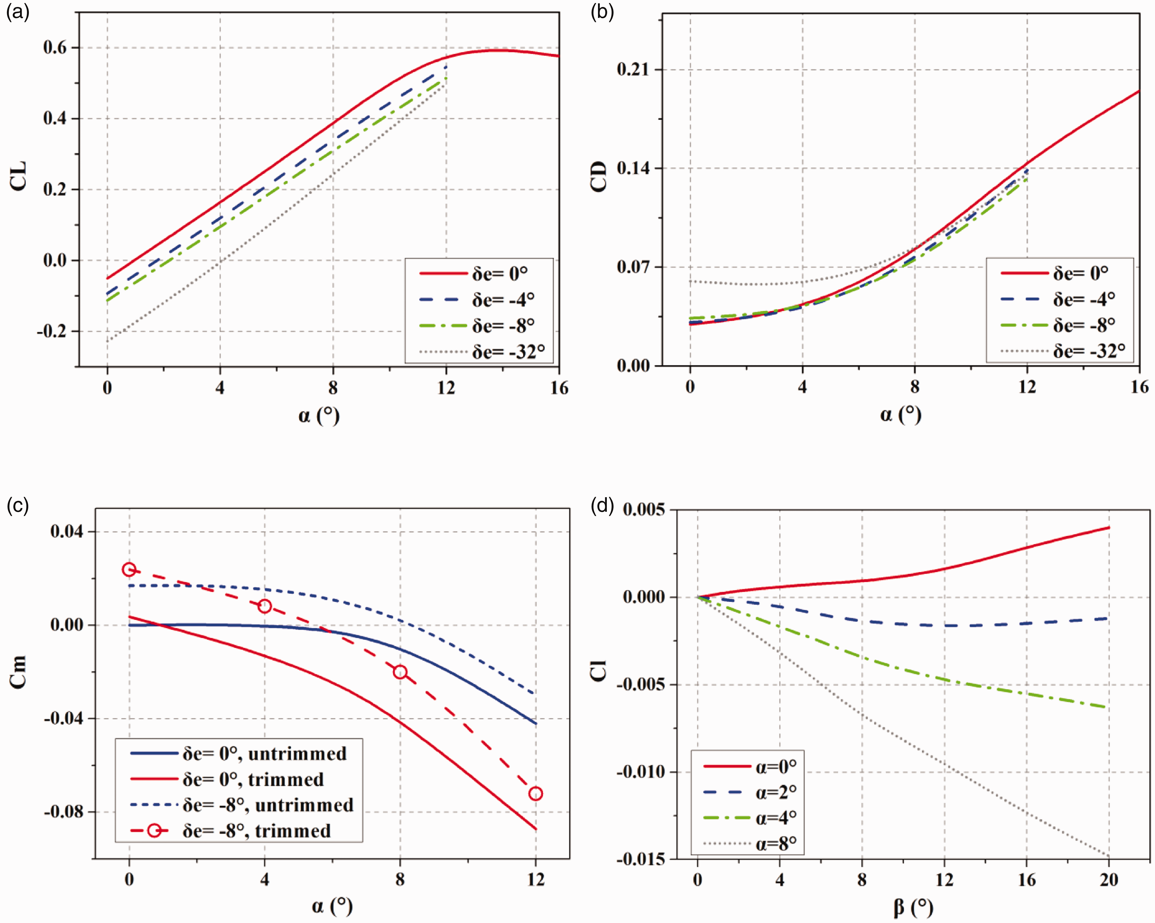
Aerodynamic results computed by CFD method. (a) Lift coefficient. (b) Drag coefficient. (c) Pitch moment coefficient. (d) Roll moment coefficient.

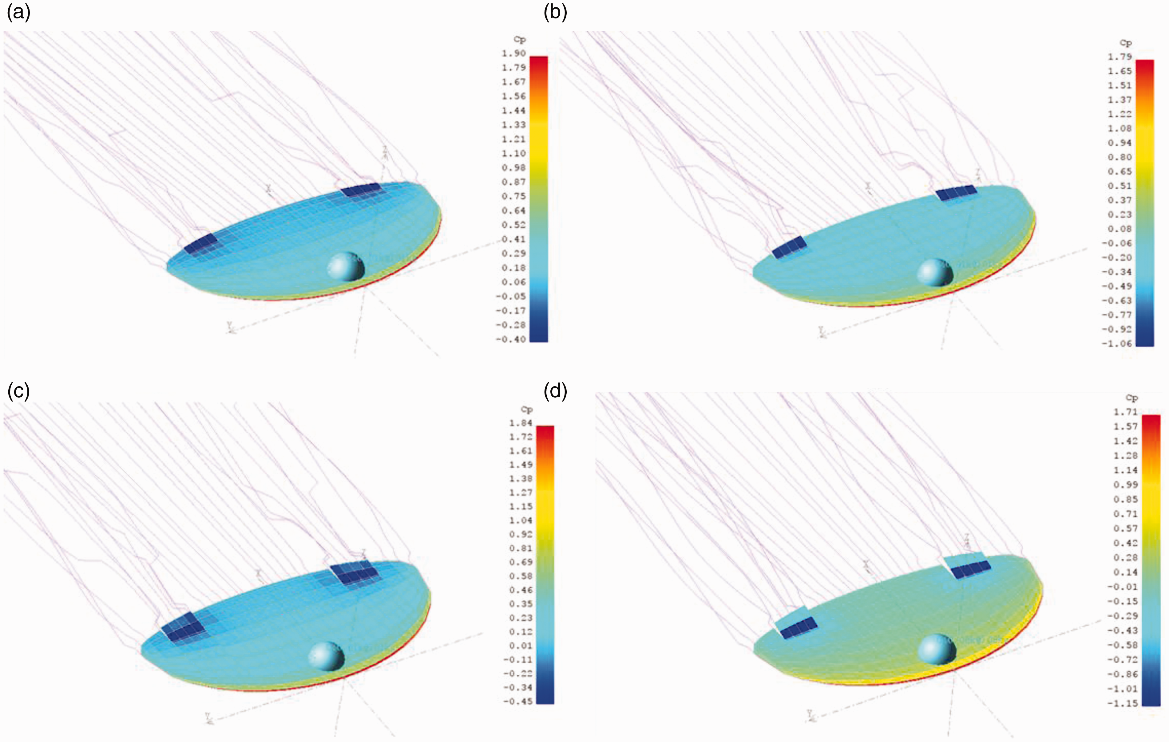
Pressure with sideslip stream angle β = 16° with different α. (a) α = 0° upper surface. (b) α = 0° lower surface. (c) α = 5° upper surface. (d) α = 5° lower surface.
Aerodynamic coefficients and inertia parameters for the micro glider.

Circuit and structure design
Due to the simple and low cost demand of the structure, all the electronic components must be easy to obtain. Main sensors of the micro glider used in control system composed of a U-blox GPS, a 9-axis IMU and a STM32 SCM (CPU). The radio system is removed from a weather sonde to transmit data (downlink including the position and control outputs) to the ground station. The effective range of the radio is about 100 km. Two micro servos actuated by PWM siginal are used to control elevons. One main 3.7 V 2000 mAh lithium battery powers the electronic system and one ancillary 3.7 V 600 mAh lithium battery for powering the heating film to warming the main battery at high altitude. The main battery could power the electronic system for about 3 h. All components are placed along the central line region. Because the batteries are heavier (about 30 g) than other components, they are placed at the front for adjusting the position of CG. The structure and circuit layout design are shown in Figure 6.

Conceptual design of micro glider. (a) Structure design. (b) Electronic system design.
The wing planform shown in Figure 7(a) was fabricated by a laser cutting machine. We selected 1 mm thickness PCB as the wing material due to the strength demand. Thickness lower than 1 mm will result in wing deformation in high dynamic pressure. Lightening hole was all distributed at the rear region and was sealed by sellotape to maintain the origin planform, as shown in Figure 7(b). The elevons and the servo actuators are connected by two aluminium-made push-pull rods. The geometrical relationship between the stroke of the servo motor and the elevon deflection angle is about 4°/mm. Figure 7(c) shows the soldered sensors. Fuselage shown in Figure 7(d) is fabricated by 3D print, providing the space for the batteries and radio component.

Main components for fabricating the micro glider. (a) Wing planform, tail, pushrod and elevon. (b) Servo actuator. (c) CPU, GPS and 9-axis IMU. (d) Fuselage, batteries and communication link component.
Flight control design and simulation
Dynamic model linearization
Nominal flight conditions are also determined by solving translation motion equation (2) based on trimmed condition 

Nominal flight parameters.
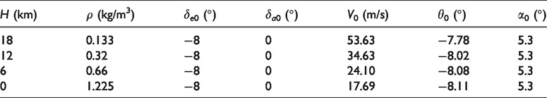
Figure 8 presents the longitudinal and lateral-directional response by solving equations (1) and (2). For longitude channel zero-input response, the response of α takes 15 s to recover. Compared to α, gliding path angle γ, pitch angle θ, and velocity response are relatively slow, which take about 60 s to recover to stability. However, considering the self-stable ability of the micro glider, the pitch control in longitude may not be indispensable. For lateral-channel zero-input response, all parameters show a quick response to recover to stability, which validates the effectiveness of the elevon design for controlling the roll motion. In conclusion, the phugoid mode, the roll mode and the Dutch-roll mode are stable.

Micro glider longitude and lateral stability response. (a) Longitude zero-input response. (b) Longitude zero-stat response. (c) Lateral zero-input response. (d) Lateral zero-stat response.
Control law design
General control method of the flying wing configuration is implemented by dividing the elevons motion into an elevator motion and an aileron motion under the small deflection angle condition. The turning of the micro glider is achieved by changing the bank angle (bank to turn, BTT), which means an incremental aileron deflection angle 
Lateral-directional channel
Based on the sensor ability, roll rate p and roll angle
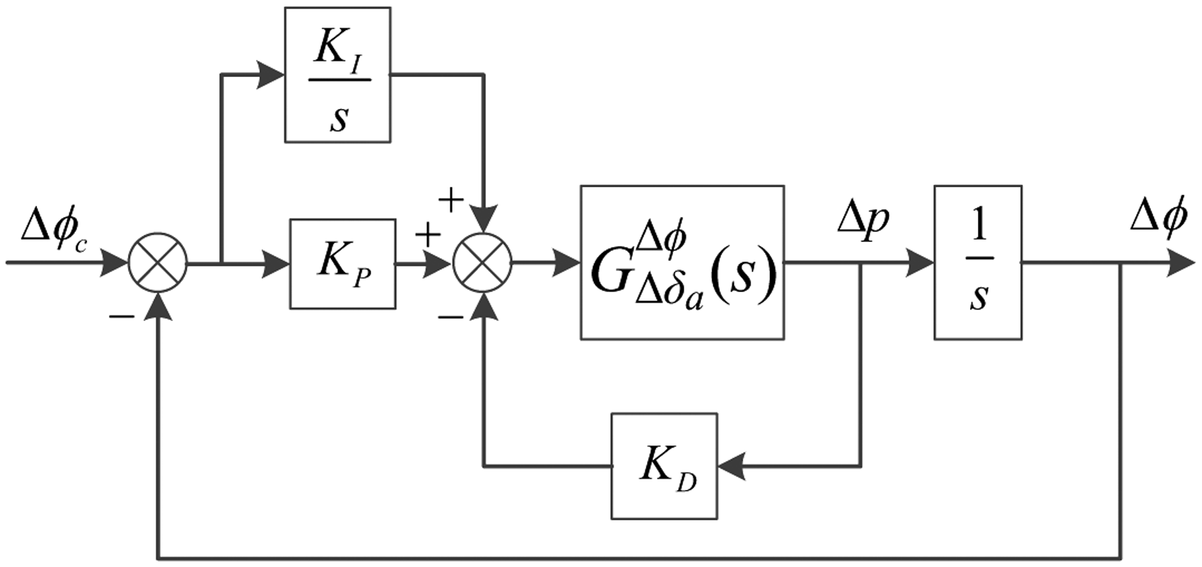
Roll control loop design.
For simplifying roll control design, firstly equation (2) needs to be re-written as follows
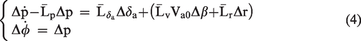
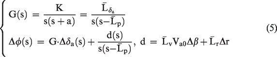
Based on equation (4), the simplified transfer function could be expressed in equation (5)

Longitudinal channel
Longitudinal channel control is dependent on the simplified transfer function formulated as below


Pitch control loop design.
Guidance law design
Based on the overall analysis and control design in the sections ‘Aircraft design’ and ‘Control law design’, firstly the micro glider after launching will fall without control for a certain distance to recover to the equilibrium glide state and then the guidance law will be activated. The micro glider maintains steady flight in the longitudinal plane and only operates guidance law in the horizontal plane. As abovementioned, turning is implemented by changing the bank angle. As can be seen from the lateral guidance loop shown in Figure 11, the guidance law includes three parameters, which are course angle

Complete lateral guidance loop.

Simplified guidance loop.
In guidance law design, for no wind and no side slip angle condition, BTT control could be expressed as the coordinated turn, as shown in equation (8). The turning radius could be computed by equation (9)


By generating the desired course angle rate 
Straight line mode guidance law
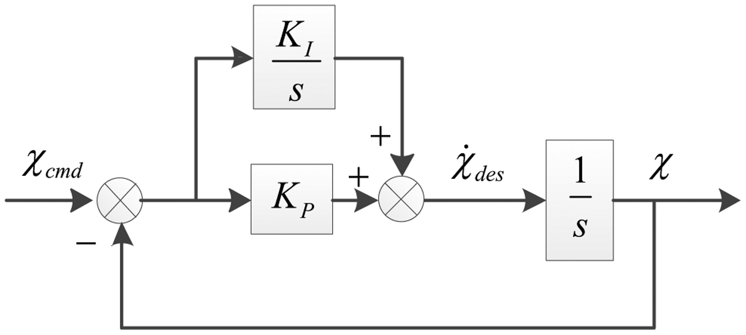
In straight-line mode guidance law, it demands that the velocity vector of the micro glider always directs to the guidance waypoint. In other words, the command course angle 

Straight model guidance loop.
For maintaining the stability of the control loop, the damping ratio is defined larger than 1 for achieving an overdamped system. It allows a smooth flight path variation for the micro glider. Based on the simulation results, Kp and KI are tuned to 2 and 0.5. The control loop of the straight-line mode guidance is shown in Figure 13.
Spiral descent mode guidance law
In this mode, the micro glider enters a spiral orbit around the target waypoint as the line of sight distance is close enough. In this stage, shown in Figure 14, depending on the error of course angle 

Orbit entry selection.
By analogy to the straight-line mode, the command line of sight angle 

The control loop for spiral descent mode is shown in Figure 15. According to the control loop, the close loop transfer function is expressed as below


Spiral mode guidance loop.
Mode switch
As described above, guidance law for the micro glider only operates in the horizontal plane, which means the minimum turning radius is the index parameter for circle flight guidance. As shown in Figure 16, at the condition of the line of sight distance larger than N1R, straight-line mode is activated. At the condition of the line of sight distance less than N2R, spiral descent mode is activated. Besides, at the interval of [N2R, N1R], magnetic hysteresis is adopted for the guidance mode switch. The values of N1 and N2 are tuned to 5 and 3 based on simulations, which could produce a smooth circle orbit.

Mode switch between straight mode and spiral mode.
During the guidance process, the micro glider roll amplitude is limited by multiplying a scaled-down coefficient 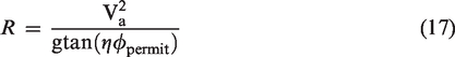
As the principle of constant dynamic pressure during flight, the velocity of the micro glider varies with the altitude and hence the minimum turning radius needs to be updated synchronously to judge the guidance logic.
Both straight mode guidance and spiral mode guidance consist of two parts. Firstly it computes the command course angle 
Simulation results
For validating the control and guidance law design and comparing the flight path with and without wind effects, two initial heading angles

3D (left) and planar (right) path with no wind condition.
Controller outputs with no wind conditions.
In wind effect simulations, flight performances at two maximum wind velocities of

3D (left) and 2D (right) path with wind condition.

Controller outputs with wind field conditions.
The last part simulated the abovementioned maximum roll angle
Parameters tuning in program. (a) Path with different
Flight test
The flight tests of two micro gliders as a sub-payload of a 3000 m3 super pressure balloon were conducted in Inner Mongolia, China, as shown in Figure 22. The two micro gliders were launched at the altitudes of 10,000 m and 20,000 m. It takes the balloon about 40 and 82 min to ascend to the launch altitudes, respectively. Attitude control for both lateral and longitude direction is activated after the initial launches. The landing waypoint is the same as the balloon lifting-off position, where the longitude = 108.382070° and latitude = 41.696889°.

Super-pressure balloon, gondola and micro gliders before lifting-off.
Figure 23 shows the high altitude micro gliders launching process captured by the camera on the balloon gondola. As shown in Figure 23(a), we can see the first glider rolled over after separated from the slide rail. One possible explanation for this initial roll motion is that the strong wind zone at 10,000 m attitude produced an in-balanced roll moment on both sides of the wing. As suddenly separated from the slide rail, the micro glider lost the constraint and was driven by the moment to roll. The initial roll speed resulted in a tail spin at the initial stage and also resulted in the loss of the radio link. The re-receiving of the radio signal from the micro glider was at about 8000 m altitude, which is shown by 3D and planar path by Figure 24(a) and (b). After 8000 m, the glider had already recovered from tail spin and turned into a stable flight attitude. However, the path of the first glider still showed a strange self-induced spiral descent. Apparently, it was not dominated by the flight control program. We prefer to explain it by fabrication error, such as the deflection angle errors between the right and left elevons or the center of mass deviation. In previous low altitude uncontrolled launched tests, the spin tail correction and spiral flight were both observed. Because most of the time the micro glider was in self-induced spiral flight, the airline distance from the launching position to the landing position was only 3.3 km. The total flight time was 19 min. The second micro glider launched at 20,000 m kept a stable initial attitude after separating from the slide rail, as shown in Figure 23(b). It may attribute to the mild wind field of the quasi-zero wind layer at 20 km altitude. The loss of radio link also happened during the flight. The glide path for the second micro glider was relatively straight, as shown in Figure 24(a) and (c)). However, it still failed to turn to the waypoint. The airline distance was about 15.8 km, which glided for about 26 min.

Screenshot of the launch at the two altitudes. (a) Launch at 10,000 m. (b) Launch at 20,000 m.
Flight paths of the launch tests. (a) Balloon (yellow) and micro glider (purple) 3D path. (b) 1st micro glider 3D and planar paths. (c) 2nd micro glider 3D and planar paths.
From the aircraft design point of view, the successful launch and flight tests verified the feasibility of designing a PCB fabricated micro glider to fly at high altitudes. The gliding process from launch to equilibrium flight indicates the trim condition calculated by panel method and CFD method is acceptable. However, the real flight duration of 26 min was lower than the ideal duration of 36 min obtained by simulation at no wind condition. It is mainly because the real micro glider shape is more complex compared to the ideal numerical model, which causes more parasitic drag in flight. Furthermore, the real atmosphere wind field including gust and adverse wind direction will also decrease the flight range. Thirdly, the tail spin or stall at the initial launch also shortens the effective altitude.
Figure 25(a) and (b) presents the flight data from the sensors on the two micro gliders. The north and east GPS velocities of the first micro glider show strong fluctuations caused by the spiral path. The true pitch angle of first micro glider also shows fluctuations from −10° to 15°, which is because the course angle in spiral flight is continuously changing with respect to the real wind field. This variation caused Va fluctuations, and thus resulted in θ continuous fluctuations. To adjust the θ to the nominal condition of −8°, it can be seen that the controller computed command δe matches the frequency of the θ fluctuation. For the second micro glider, because the path and θ are relatively stable, command δe outputted a limited value of 5° to adjust θ to nominal condition. Roll angle showed it tracked the command roll angle actuation frequency, but did not track the amplitude of command

Controller outputs for the launch tests. (a) 1st micro glider. (b) 2nd micro glider.

3D (left) and planar (right) path with the consideration of initial elevon errors.
Controller outputs for initial δa0 errors. (a) Command course angle. (b) Errors between right and left elevon deflection angle.
Based on the high altitude launch test results, both the aerodynamic design and control algorithm need to be improved. Potential improvements are concluded in four parts. Firstly, the roll and pitch coefficients in the aerodynamic model are referred to as a linear non-coupled model. However, for a flying wing aircraft, particular for the flat-plate wing that the trim condition is maintained by the elevons deflection, nonlinear aerodynamic coefficients at large elevon deflection angle resulted in couple effects between roll and pitch angle, which may cause errors by using linear elevon control model of δa and δe. The precise calculation method and new aerodynamic model need to be developed. The elevons separated the aerodynamic model may be more accurate for flat-plate flying wing MAVs. 20 Secondly, the accuracy of fabrication needs to be enhanced. Effectiveness for the increase of δa, limited will be validated in the further launch tests. At last, the current circuit design does not include the heading sensor. In the further micro glider design, a micro heading sensor or a wind estimated algorithm would be necessary to be included in the control system to provide a more precise heading angle.
Conclusion
This article presents the design details of the aerodynamics and control system for a print circuit board fabricated micro glider launched from high altitude with only limited sensors. Control algorithm at no wind condition with the specified aerodynamic design showed a possibility to control micro glider to land precisely around the target waypoint within a distance error less than 200 m. Simulations with the ideal wind model indicated that the controller performance is mainly determined by the wind velocities and directions. For flight with a headwind of
Footnotes
Data availability
The data used to support the findings of this study are available from the corresponding author upon request.
Declaration of conflicting interests
The author(s) declared no potential conflicts of interest with respect to the research, authorship, and/or publication of this article.
Funding
The author(s) disclosed receipt of the following financial support for the research, authorship, and/or publication of this article: This research is supported by the National Nature Science Foundation of China under Grant no. 61703389. The experiment part stated in the article is supported by the Strategic Priority Research Program of Chinese Academy of Sciences under Grant no. XDA17020100.